Eding CNC UIO-10 User manual

User Manual UIO-10
DRAFT –WORK in PROGRESS
Please note, the current IO-10 Setup is in Beta modus. There are several things we want to improve.
However, we’re always happy to get some feedback.

Document History
Version
Date
Author
Comment
© Copyright EdingCNC B.V.
All rights reserved. Reproduction in whole or in part prohibited without the prior written consent of the
copyright owner.

Table of Contents
1. Connecting the board ...........................................................................................................................4
2. UIO-10 Hardware conncetions..............................................................................................................6
On/Off switch............................................................................................................................................6
Toggle Switch............................................................................................................................................6
Rotary Switch............................................................................................................................................6
Handwheel................................................................................................................................................6

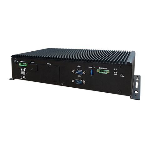
This manual describes how to use the EdingCNC UIO-10.
1. Connecting the board
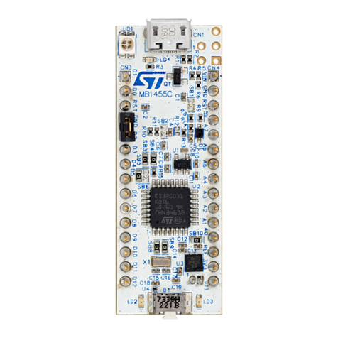
After the board has been connected with a USB cable with Mini USB-B connection start the software.
<TODO: How is board reported under windows???)
The software should detect it, this is shown in the message window.

LED1/LED3 Toggle = Bootloader modus, after about 10 seconds continues.
JP1 = Skip bootloader
IO17
IO32
IO1
IO16
2x 5V
Mini
USB
2x 3.3V
GND

2. UIO-10 Hardware conncetions
Toggle switch
A toggle switch is a typical switch that once switch remains in that position.
Momentary Switch
A momentary switch is a switch that is only active when it is pressed, on release if will automatically
disconnect.
Rotary Switch
A rotary switch is a switch that has multiple terminals.
A rotary switch is considered the same as a normal switch, to use it you can connect the centre
connection to ground, and the outputs to the inputs you like to use.
Handwheel
Up to 3 handwheels can be connected to the UIO-10. However it’s important to note that only on 6
inputs are able to connect a handwheel on. Connecting on other inputs can damage the UIO-10.

Setup the software:
Note, make sure when configuring your UIO-10 that your controller card is also connected.

Test connection:
Connected switch, for example IO17.
Now click on ‘6) Testmode on/off’.
And observe that it will show when the input is active by turning green.
To continue, deselect ‘6) Testmode on/off’.

Adding switch function:
Let say we want to add a function to this switch:
When the switch is turned ON it should switch on the spindle, and when you switch it OFF the spindle
should stop.
You do this in several steps:
1. Select that you want to add a ‘Simple Switch’and a rule number, in this case #1
2. Select the input you want it to connect to, in this case #17
3. Select what it should do when you switch it ON, this is ‘option 1’→“SPINDLE ON R”
4. Select what it should do when you switch it OFF, this is ‘option 2’→“SPINDLE OFF”
5. Press ‘Save Settings’
6. Press ‘Configure UIO Board’
7. Press ‘Done’
If you back in the main program switch it and observe that you can switch the spindle ON and OFF.
NOTE:
If you have already allocated a function to an input, you can of course not assign it again, this is made
visible that that input is shown in a dark yellow color.

Momentary switch
If you connect a button switch this will work the same, you can either have something be active as long
as you press a button. For example, jogging. You can select ‘Start Jog Plus X’as action #1 (the press
down action), and select ‘Stop Jog’as action #2 (the release action). This would result in being able to
jog until you release that button.
For other functions, there is no need to define a ‘release’action simply because this is a toggle function.
For example, using the ‘TOGGLEAUX1’function. You would only define the first action:
Each time you press the button it will automatically toggle AUX1 between ON and OFF.

Rotary switch
You can add up to 4 rotary switches. This time you need to select the ‘Selector switch’, and you can
select the number of inputs you are using, each input will be purple to indicate that these are used for a
‘selector switch’. For each input you select an extra action will be shown on the right side of the screen.
Handwheel
Up to 3 handwheels can be connected to the UIO-10. Not all inputs of the board can be used for
handwheels.
The inputs that can be used are:
I016 –A
IO18 –B
IO24 –A
IO25 –B
IO26 –A
IO28 - B
Also indicated above is the suggested output A or B that can be connected. If your handwheel turns the
wrong way you can simple re-wire A and B connection.
By selecting an axis through a (rotary) switch and using the handwheel you can control the position of
the machine.
Note, remember you also need to de-activated the selected axis!
Table of contents

