manuals.online logo
Brands
  1. Home
  2. •
  3. Brands
  4. •
  5. Crown
  6. •
  7. Computer Hardware
  8. •
  9. Crown IQ-P.I.P.-SLM User manual

Crown IQ-P.I.P.-SLM User manual

@crown®* System®Product Reference
IQ System P.I.P.-SLM
OVERVIEW
An IQ System amplifier is a Crown am-
plifier (MA Series, CT Series, or Refer-
enceSeries)thatisequippedwithanIQ
P.I.P.®Programmable Input Processor
input module. The IQ P.I.P.-SLM is one
such input module. The P.I.P.-SLM in-
cludes the “basic” and “SLM” feature
sets, auto-standby and EEPROM
memory backup. The P.I.P.-SLM is fully
PIP2compatible. The P.I.P.-SLM is an
IQ2component and requires an IQ2
compatible interface for communica-
tion with a computer.
CROWN AMPLIFIERS
TherearethreefamiliesofCrownampli-
fiers which are fully IQ System compat-
ible. They include the Macro-Tech Se-
ries for professional PA, the Com-Tech
Seriesforcommercialinstallations,and
theReferenceSeriesforstudioapplica-
tions. In the case of the P.I.P.-SLM,
however, it should only be installed in a
PIP2amplifier such as the CT “10” Se-
ries.
P.I.P.-SLM PROCESSING
The P.I.P.-SLM allows you to communi-
catedirectlywithan amplifier whether it
is sitting on a bench next to you or
mounted in rack hanging from a loft.
Before the advent of IQ, it was impos-
sible to directly control and monitor
amplifiers unless you were physically
present at the amplifier. Even then your
abilities were limited by the physical
featuresofthe amplifier. Todayyoucan
control amplifier attenuation in half dB
steps, and control a host of other func-
tions. Unlike other amplifiers, you also
haveaccesstothermalheadroominfor-
mation and visual status of signal level
and distortion.
The P.I.P.-SLM module includes
EEPROM memory backup. This feature
allows the onboard processor to main-
tain its memory in the event that main
AC power is lost, disconnected, or
switched off at the front panel.
The System and Load Monitor feature
setaddstheabilitytoperformreference
and test sweeps and plot results, then
report the results as pass-fail based on
your defined criteria. Additional auto-
mation includes auto-standby for en-
ergy conservation.
PHYSICAL ATTRIBUTES
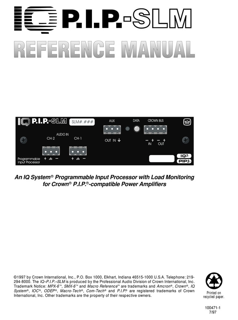
All P.I.P.-SLM is about the size of a 3 x
5 card, and the panel face (shown
above)mounts flush with the rearpanel
of the amplifier.
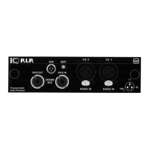
Front Panel
• Euro-style 3-pin barrier block audio
input connections per channel.
•Euro-style4-pinbarrierblockconnec-
tor for Crown Bus data loop.
•Euro-style3-pinbarrierblockconnec-
tor to send or receive external control
voltages.
•DSPI(data)LEDinformsyouwhenthe
unit is receiving data, and can also be
used for troubleshooting.
• Dual function memory reset switch is
accessible from the front panel, how-
ever it is recessed and unmarked to
prevent unintended operation. Press
once to reset unit to custom default,
press and hold to reset to factory de-
fault.
Circuit Boards
•Twomulti-layerprintedcircuitboards.
• Loop address eight segment DIP
switch. Up to 250 IQ amplifiers may
operate on a single data loop.
• PIP2Jumpers (set to OUT position
when used in a PIP2amplifier) to com-
pensate output meter scaling depend-
ing on amplifier type.
• PIP2Resistor Packs must be installed
when the module is installed in a PIP2
amplifier and must be removed if used
in a non-PIP2amplifier.
Note: The pri-
mary purpose of this module is to sup-
port internal load monitoring. This can
only be done with a PIP
2
amplifier.
P.I.P.-SLM
P.I.P.-SLM (Page 1 of 3)
OUTIN
Programmable
Input Processor
AUDIO IN
CH-2 CH-1
AUX
OUT IN
DATA CROWN BUS
SLM#.###
BOTTOM
OUTIN
Programmable
Input Processor
AUDIO IN
CH-2 CH-1
AUX
OUT IN
DATA CROWN BUS
SLM#.###
SW1
View of SW1 Address
Switch
1
2
4
8
16
32
64
128
VALUE
TOP VIEW
12345678
ON
SW1
SW1 Address Switch
@crown®* System®Product Reference
Installation
Before installing the P.I.P.-SLM into the
amplifier you must first configure the
switches, jumpers, and install or re-
movethePIP2resistorpacksasneeded.
When initial configuration is complete,
remove the existing P.I.P. from the am-
plifier and move the P.I.P. connector to
the P.I.P.-SLM. Set the amplifier sensi-
tivityto the desired position. Theribbon
cablefoldsupasyouinsertthemodule.
IQ MONITORING
Refer to the P.I.P.-SLM Block Diagram.
•Pre-fadeinputlevels(+20to–40dBu).
• Amplifier output signal level (0 to –40
dB re scaled rated output).
• IOC (Input/Output Comparator) indi-
cates distortion >0.05%.
• ODEP (Output Device Emulation Pro-
tection). ODEP is an amplifier circuit
that calculates thermal headroom of an
amplifier and is reported in IQ as a per-
centage of thermal headroom used.
• Aux Port input sense.
P.I.P.-SLM (Page 2 of 3)
P.I.P.-SLMBasic Block Diagram
IQ CONTROL
Refer to the P.I.P.-SLM Block Diagram.
The P.I.P.-SLM supports the complete
basic feature which consists of:
• Power (high voltage rails).
• Mute.
•Attenuation (0.5 dB steps from 0 to80
dB).
• Polarity (XLR pins 2 and 3).
• Aux Port output voltage.
• DSPI/Data LED.
• Memory backup.
• User defined default memory.
• Output meter scaling.
AUTO STANDBY
Energy conservation is automated with
this function that allows the amplifier to
idle at a fraction of its normal idle draw.
Perchannelwiththefollowingvariables:
—On-Off
—Threshold (input)
—Turn-off Delay (minutes)
—Turn-on Delay (one switch for both
channels,when on adds a delay based
on address and when off the amplifier
powersup within 8 msec afterbreaking
threshold)
SLM FUNCTIONS
SystemandLoadmonitoringisthemajor
feature benefit of the P.I.P.-SLM. The
purpose of the SLM function is to verify
repeatability of performance of the au-
dio system. Reference data is first es-
tablished and subsequent test sweeps
are performed to prove that system
operation is constant. The impedance
response test proves that the load per-
formance is constant while frequency
response proves that the electronics
are a constant. When syncronized with
an external sweep generator (such as
the SLM-8) full system frequency re-
sponse can be measured.
Thesignalgeneratorisusedtoperform-
ing sweeps or to produce a constant
tone. To perform a sweep you must
configure the generator and data ac-
quisition. The tolerance criteria you set
determineswhetherthe test will passor
fail. The following is a complete list of
parameters associated with the SLM
functions:
—Sweep Enable
—Oscillator Enable
MICROCONTROLLER
DIGITALLY
CONTROLLED
ANALOG
ATTENUATOR
A / D
CONVERTER
IOC
ODEP
AUX IN
MONITOR INPUTS
INPUT MUX
A/D CONV.
8K x 8
EEPROM
AMP OUTPUT
VOLTAGE
BALANCED
AUDIO INPUTS POLARITY INVERT
& OUTPUT BUFFER
CH 1
CH 2
AUDIO OUTPUTS
1
2
CH 1
CH 2
CH 1
CH 2
CH 1
CH 2
AMP OUTPUT
CURRENT
PIP INPUT
LEVEL
REF VOLTAGE
RESET
AUX OUT
REM STANBY
DATA LED
IQ ADDR SWITCH
CROWN BUS
SERIAL
DATA INPUT
CROWN BUS
SERIAL
DATA OUTPUT
INPUT
RECEIVER
OUTPUT
DRIVER
DROP-OUT
RELAY
8K x 8
RAM
1
2
1
2
BUFFER
STAGE
+
-CH 1
CH 2
+
-
BALANCE
TO SINGLE
ENDED CONV.
BALANCE
TO SINGLE
ENDED CONV.
DDS SINE
WAVE GEN.
DIGITALLY
CONTROLLED
ANALOG
SWITCH
2
BUFFER
STAGE
1
@crown®* System®Product Reference
P.I.P.-SLM (Page 3 of 3)
—Sweep Resolution
—Sweep Start Frequency
—Sweep Stop Frequency
—Oscillator Frequency
—Generator Amplitude
—Acquisition Mode
—Start/Abort Sweep
—Impedance Response Tolerance
—Frequency Response Tolerance
—Report Pass-Fail at Aux
—Start/Abort Via Aux
SOFTWARE SUPPORT
The P.I.P.-SLM is supported by the
Turbo 1.4, and Sys-Config II DOS soft-
ware packages as well as the IQ For
Windows software package.
P.I.P.-SLM SPECIFICATIONS
Audio specifications are referenced to
0dBu,measurementstakenattheedge
connector of the module itself.
Aux Port:Aux Port:
Aux Port:Aux Port:
Aux Port:Pin 1 is tied to ground. Pin 2is
a sensing input capable of sensing an
analog voltage or digital state. Pin 3 is
highimpedancewhenswitchedofffrom
software, +15 VDC at 15 ma when
switched on from software.
BACK PANEL
OF PIP2
AMPLIFIER
OUTIN
Programmable
Input Processor
AUDIO IN
CH-2 CH-1
AUX
OUT IN
DATA C ROWN BUS
SLM#.###
P.I.P.
MODULE
Slide PIP2 Into Amplifier
BACK PANEL
OF PIP2
AMPLIFIER
OUTIN
Programmable
Input Processor
AUDIO IN
CH-2 CH-1
AUX
OUT IN
DATA C ROWN BUS
SLM#.###
Rotate PIP2 180° in
opposite direction
BACK PANEL
OF PIP2
AMPLIFIER
18 PIN (B)
B
A
20 PIN (A)
OUTIN
Programmable
Input Processor
AUDIO IN
CH-2 CH-1
AUX
OUT IN
DATA C ROWN BUS
SLM#.###
Rotate PIP2 180°
BACK PANEL
OF PIP2
AMPLIFIER
18 PIN (B)
20 PIN (A)
Plug In CABLE B
B
A
OUTIN
Programmable
Input Processor
AUDIO IN
CH-2 CH-1
AUX
OUT IN
DATA C ROWN BUS
SLM#.###
BACK PANEL
OF PIP2
AMPLIFIER
18 PIN (B)
20 PIN (A)
Plug In CABLE A
B
A
OUTIN
Programmable
Input Processor
AUDIO IN
CH-2 CH-1
AUX
OUT IN
DATA C ROWN BUS
SLM#.###
Power Requirements:Power Requirements:
Power Requirements: Unregulated
±24VDC from amplifier.
Memory Backup:Memory Backup:
Memory Backup: EEPROM maintains
memory with amplifier power off. Rated
at greater than 10,000 writes. Changes
are written to EEPROM memory ap-
proximately 30 seconds after the last
command to change a setting is re-
ceived.
Data Rate:Data Rate:
Data Rate: 38,400 baud.
Data Format:Data Format:
Data Format: Serial, binary, asynchro-
nous, 1 start bit, 1 stop bit, 8 data bits,
no parity.
Data Protocol:Data Protocol:
Data Protocol: IQ2protocol.
Interface Type:Interface Type:
Interface Type: Isolated 20 ma current
loop.
Operation:Operation:
Operation: Half duplex.
Intelligence:Intelligence:
Intelligence: 8 bit processor with 20 KB
firmware.
Input Impedance:Input Impedance:
Input Impedance: Nominally 20K Ohm
balanced, 10K Ohm unbalanced.
Signal/Noise:Signal/Noise:
Signal/Noise: >85 dB 20 to 22 kHz.
Frequency Response:Frequency Response:
Frequency Response:±0.1 dB 20 to 22
kHz.
Crosstalk:Crosstalk:
Crosstalk: >70 dB at 1 kHz, >65 dB at
20 kHz.
T.H.D.:T.H.D.:
T.H.D.:T.H.D.:
T.H.D.: <0.05% 20 to 22 kHz.
GuaranteedExcellence
@crown
Crown International, Inc.
PO Box 1000 Elkhart, IN 46515-1000
Ph. 800-342-6939/219-294-8200
Fax 219-294-8301
Internet: www.crownaudio.com
Trademark Notice:Trademark Notice:
Trademark Notice:
IQ System
®
and
P.I.P.
®
are registered
trademarks of Crown International Inc.
PIP
2
Installation

Other manuals for IQ-P.I.P.-SLM

1

Other Crown Computer Hardware manuals

Crown IQ-PIP-USP3/CN User manual

Crown

Crown IQ-PIP-USP3/CN User manual

Crown P.I.P.-BP1C User manual

Crown

Crown P.I.P.-BP1C User manual

Crown PIP-ATX User manual

Crown

Crown PIP-ATX User manual

Crown IQ-PIP-USP3 User manual

Crown

Crown IQ-PIP-USP3 User manual

Crown P.I.P.-102 User manual

Crown

Crown P.I.P.-102 User manual

Crown IQ-P.I.P User manual

Crown

Crown IQ-P.I.P User manual

Crown PIP-EDCB User manual

Crown

Crown PIP-EDCB User manual

Crown IQ-P.I.P-SMT User manual

Crown

Crown IQ-P.I.P-SMT User manual

Crown IQ-P.I.P.-SLM User manual

Crown

Crown IQ-P.I.P.-SLM User manual

Crown IQ-PIP-LITE User manual

Crown

Crown IQ-PIP-LITE User manual

Crown ScreenArray PIP-3632 User manual

Crown

Crown ScreenArray PIP-3632 User manual

Crown PIP-BEQ User manual

Crown

Crown PIP-BEQ User manual

Crown PIP-AF User manual

Crown

Crown PIP-AF User manual

Crown PIP-ATN User manual

Crown

Crown PIP-ATN User manual

Crown PIP-FXT User manual

Crown

Crown PIP-FXT User manual

Crown IQ-PIP-USP2 User manual

Crown

Crown IQ-PIP-USP2 User manual

Crown PIP-FPX User manual

Crown

Crown PIP-FPX User manual

Crown IQ-P.I.P-AP Assembly instructions

Crown

Crown IQ-P.I.P-AP Assembly instructions

Crown IQ-PIP-USP2 User manual

Crown

Crown IQ-PIP-USP2 User manual

Crown PIP-XOV User manual

Crown

Crown PIP-XOV User manual

Crown IQ-PIP-USP2 User manual

Crown

Crown IQ-PIP-USP2 User manual

Crown IQ-PIP-LITE User manual

Crown

Crown IQ-PIP-LITE User manual

Crown ScreenArray PIP-3632 User manual

Crown

Crown ScreenArray PIP-3632 User manual

Crown IQ-PIP-USP2 User manual

Crown

Crown IQ-PIP-USP2 User manual

Popular Computer Hardware manuals by other brands

Acqiris SA240P user manual

Acqiris

Acqiris SA240P user manual

iWave FIP-2420 user manual

iWave

iWave FIP-2420 user manual

GE D20MX user manual

GE

GE D20MX user manual

Raith ELPHY Quantum Hardware operation manual

Raith

Raith ELPHY Quantum Hardware operation manual

Epson S1C33 Series Core Manual

Epson

Epson S1C33 Series Core Manual

Fujitsu 8FX Hardware manual

Fujitsu

Fujitsu 8FX Hardware manual

Encore ENMMP-U41 user manual

Encore

Encore ENMMP-U41 user manual

Kontron COMe-cDC2 user guide

Kontron

Kontron COMe-cDC2 user guide

Arcom SBC104 Technical manual

Arcom

Arcom SBC104 Technical manual

NUDEcnc Ncore V1 instruction manual

NUDEcnc

NUDEcnc Ncore V1 instruction manual

ST STM32U5 user manual

ST

ST STM32U5 user manual

TRENDnet TE100-PCBUSR - DATA SHEETS Specifications

TRENDnet

TRENDnet TE100-PCBUSR - DATA SHEETS Specifications

Alphacool GPX-N 1080-M01 instruction manual

Alphacool

Alphacool GPX-N 1080-M01 instruction manual

Measurement Computing Switch & Sense 8/8 user guide

Measurement Computing

Measurement Computing Switch & Sense 8/8 user guide

COUGAR POSEIDON LT 360 ARGB quick start guide

COUGAR

COUGAR POSEIDON LT 360 ARGB quick start guide

AES BeBoPr++ user manual

AES

AES BeBoPr++ user manual

ekwb EK-PRO GPU WB RTX 30 0 Series user guide

ekwb

ekwb EK-PRO GPU WB RTX 30 0 Series user guide

Advantech PPC-3151 user manual

Advantech

Advantech PPC-3151 user manual

manuals.online logo
manuals.online logoBrands
  • About & Mission
  • Contact us
  • Privacy Policy
  • Terms and Conditions

Copyright 2025 Manuals.Online. All Rights Reserved.