7
23. 11. 21. Document Number 672010
Nuaire | Western Industrial Estate | Caerphilly | CF83 1NA | nuaire.co.uk
MR-ECO-COOL-V
Installation Manual
8.0 CONTROLS / DESCRIPTION OF OPERATION
•MVHR will run continuously at Background/Whole dwelling duty
(Speed 1) unless it receives a 230v signal to Switched-Live input
connections SL1 or SL2.
•Cooling module will be enabled to run and MVHR enabled to
speed 3 by a 230v Switched live from wall mounted thermostat
CM-THERM-CONTROL (supplied).
•The wall mounted thermostat will control the cooling module and
MVHR unit. On reaching the set point (user defined) the Cooling
Module will operate and the MVHR will increase to speed 3. The
wall mounted thermostat also features a ECO mode which is pre-
set to 23°C (not adjustable) and can be set to operate between 1
and 24 hours by the user.
•It is recommended that, if possible, the cooling unit be interlocked
with the heating system to prevent triggering when heat is being
called for. Figure 8 shows connection to a heating system which is
normally closed via a link. This can be replaced by a suitable VOLT
FREE connection to the heating device. Contact Nuaire for further
information and to check compatibility.
•Supplied with a Summer/Winter switch. When set to summer
mode the MVHR will target a temperature under 20°C within the
apartment.
•Summer mode can be selected year round to attempt to mitigate
overheating caused by solar gains but must be selected when
cooling is expected to run (summer months).
•Winter mode ensures the MVHR will recover heat at all times.
•For further details, see MRXBOXAB-ECO5-AESC installation
manual (671861).
9.0 COMMISSIONING
To ensure the cooling module operates correctly and prevent
the thermal overload protection from tripping, there must be a
minimum airflow of 180 m3/h (50 l/s).
It is recommended the ventilation unit is set to speed 3 on supply
and extract, adjusters are set to maximum (fully clockwise).
To commission the MVHR unit providing the air flow through the
cooling module, please refer to MRXBOXAB-ECO5-AESC installation
manual (Document number 671861).
10.0 MAINTENANCE
Isolate before commencing work, make sure that the unit, switched
live and Nuaire control are electrically isolated from the mains
supply and switched live supply.
It is important that maintenance checks are recorded and that the
schedule is always adhered to, in all cases, the previous report should
be referred to.
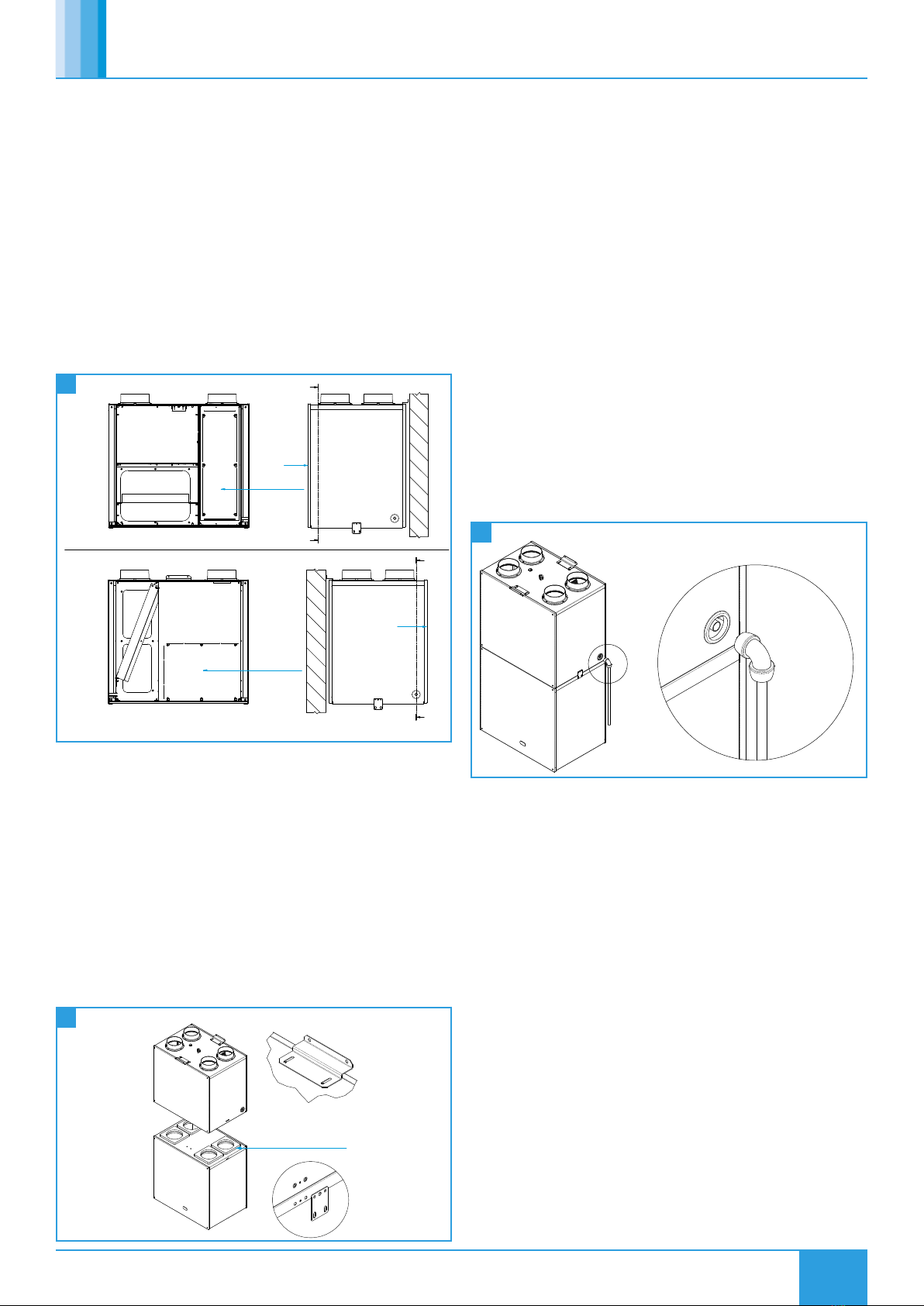
10.1 Access
Access to both Coils for maintenance can be gained by removing
the front cover of the outer case and the inner covers of the Cooling
Module.
Depending on the orientation of the unit (standard or opposite hand)
access will be given to one of the two coils. To access the second coil an
internal access panels must be removed.
Opposite hand installation do not have access to the compressor.
The compressor is sealed-for-life and requires no maintenance.
10.2 Annual Maintenance - Evaporator and Condenser
•Inspect all heat exchangers for signs of damage or dirt. Loose dirt
may be removed by using a soft brush, taking care not to brush
the dirt into the coil, blocking the fins. Damaged fins should be
combed out using a coil comb.
•If the coil is excessively dirty check that MVHR filters are still in
place.
•Filters are to be inspected every 6 months and replaced every 12
months (or sooner if required).
•If the coil is excessively dirty, use a proprietary cleaning agent, e.g.
HYDRO-COIL or MULTISOLVE.
•Inspect the condensate drain tray and clean as required.
•Check all electrical connections for tightness.
•Switch on the power to the unit. Check the operation of the
mechanical cooling system.
•Check that all the panels are in place and that the unit is in a clean
condition.
•In the event the cooling module is not operating initially inspect
the MCB in the controls.
10.2.1 Refrigeration Circuit Components
All repair and replacement work on refrigeration components must
be carried out by a fully qualified refrigeration engineer, trained
in maintenance and refrigeration recovery, and with a sound
knowledge of all relevant safety regulations pertaining to the job.
All refrigerant in the unit must be reclaimed and disposed of safely.