Edison TX-928-H User manual
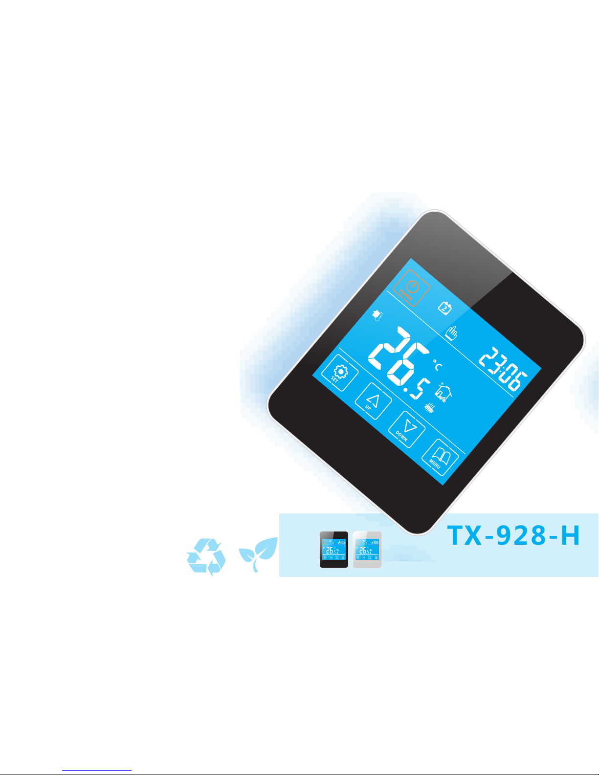
TX-928-H
The manual is subject to change without notice Version:V1-2
Operating Manual
Product Introduction 2
Product Features 2
Technical Datas 3
LCD Display and Functions 4
Dimensions 5
General Setting
Advanced Setting
Wiring Diagrams
Installation Diagrams
Trouble Shooting
Product Features
2
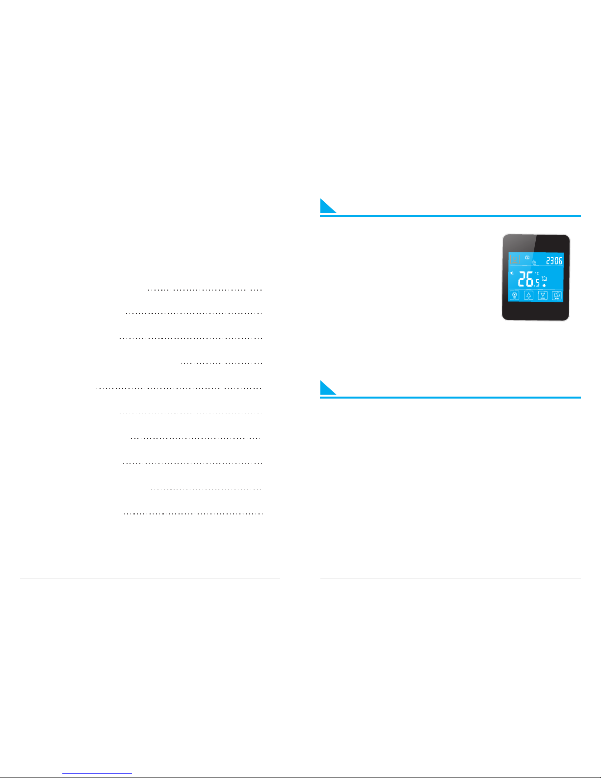
TX-928-H series are available for boiler,
manifold and underfloor heating system
with 7-day, 6-period time program
control. Models are with NTC sensor to
detect ambient and floor temperature
and do the control by compared with the
setting one. Manual, time program and
temporary mode can be switched any time by pressing the relevant
keys. De-frost protection function will be active when ambient
temperature below 5℃, prevent water pipe from freezing and
burning.
1、7-day, 6-period time program
2、Touch screen LCD with blue backlight
3、De-frost protection≤5℃
4、Key-lock function
5、Memory function (can not memorized on/ off condition)
6、Advanced setting
7、Double sensors to control and limit the temp.
8、Ingress Protection:IP20
9、Flame retardant PC
Product Introduction
CONTENTS
1
10
10
6-7
8-9
11

LCD display
LCD display and FunctionsTechnical Datas
43
Consumption:<2W
Power supply: ~240VAC 50/60Hz
Output switch: Active contact (NO) and passive contact (NO)
Max. Current
On/ Off differential temp.: 1~5℃
Transport and storage temp. : -20~60℃
Relative humidity: 10%~90% (No condensation)
Setting temp.: 5~35℃/0.5℃ per step
Accuracy: 1℃
Temp. limitation: 30~60℃(external sensor)
Wiring port: 2.5 mm²
Working temp.: 0~50℃
1. Manual control mode
LCD displays “ ”, the controller is under manual setting. In the
“ON” state, press “ ” to swich the manual control mode or time
program control mode.
2. Time control mode
LCD displays“ ”, adjust temperature of periods automatically
against time program setting. In the “ON” state, press “ ” to
switch the time program control mode or manual control mode.
3. Temporary control mode
LCD displays “ ” and “ ”, current period is manual control
mode, but next period resume to the time program control mode.
In the time program control mode, press “ ” or “ ” to enter into
temporary control mode.
Day Display
Manual Control
Time Control
Clock/
Setting Temperature/
OFF
Time Program
Heating
Menu
Reduce
Increase
Setting
Temperature Value
Power
Ambient
Temperature
20A
20 Amp Max
85
at least
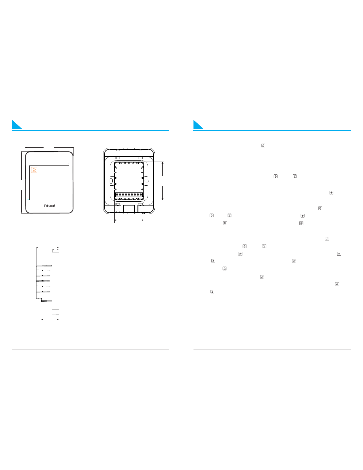
General SettingDimensions
64.1
49.2
32.2
40.6 12.4
86
110
① ②
③
5
Front View
①
②
③
Unit:mm
Back View
Left View
1. Power on / off: Presss “ ” to turn on or turn off the controller.
When power is off, it displays “OFF” and current time
alternatly; when power is on, it displays setting temp. and
current time alternatly.
2. Adjust setting temp.: Press “ ” or “ ”to adjust temp. during
manul control and temporary control mode.
3. Key-lock function: In the “ON” state, keep pressing “ ” for 3s
until the coin “LOC” displays, to lock or unlock the controller.
4. Time and week setting: In the “ON” state, press “ ”, then press
“ ” or “ ” to amend the minute; press “ ” to amend the hour;
press “ ” to set the day of week, press “ ” to save and exit the
setting.
5. Time program: In the “ON” state, keep pressing “ ” to start
setting, press “ ” or “ ” to adjust the current time(15mins/
step). Press “ ” again to check related temp., press “ ” or
“ ”to adjust setting temp.. Press “ ” to adjust next period.
Press “ ” to save and exit the setting.
6. Control mode: Press “ ” to switch manual or time program
control mode. In time control mode, keep pressing “ ” or
“ ”to enter into temporary control mode.
6

General Setting
Periods
22℃
Coins Default Time Default Temperature
WeekdaysHoliday
LOC
Wake up, Period 1 Leave(am), Period 2
Return(am), Period 3 Leave(pm), Period 4
Return(pm), Period 5 Sleep, Period 6
Key-LOC
Advanced Setting
Normally set by technicians during the first installation. Press
“ ” first, then press “ ” for 3s to enter into setting in the “ON”
state.
Tips: (Amend the datas via advanced setting, press “ ” to save and
exit the setting.)
01. Adj Temperature compensation, press “ ” or “ ” to adjust
during range -9~9℃. Press “ ” to enter into next setting.
02. Sen Sensor slection, press “ ” or “ ” to choose the sensor.
“IN”-internal sensor, “OU”-external sensor, “AL”-double
sensors. Press “ ” to enter into next setting.
03. Lit Limitation temperature of external sensor, press “ ” or
“ ” to change the exact limited temperature of external
sensor during 30~60℃, press “ ” to enter into next
setting.
04. Dif Switch deviation ( bandwidth), press “ ” or “ ” t o adjust
the differential temp. during range 1-5℃, press “ ” to
enter into next setting.
Main output from “OFF” to “ON”: Action temp.=setting temp.-
differential temp.
Ma i n ou t p u t f r o m “ O N ” t o “ O F F ” : A c t i o n t e m p . = s e t t in g
temp.+differential temp.
05. Prg 5+2/6+1/7 or off, press “ ” or “ ” to switch workdays,
5/6/7 workdays, or turn off the time program. Press “ ”
to enter into next setting .
Tips: workdays divided into 6 periods, and holidays divided into 2
periods only .
78
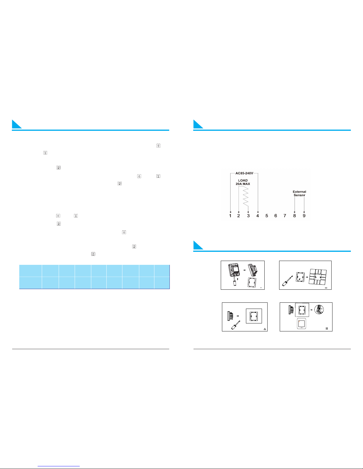
Wiring DiagramsAdvanced Setting
06. Rle Setting of passive linkage and main output, press “ ” or
“ ” to change the condition of linkage; “00” means
correspond with main loop output, “01” means opposite.
Press “ ” to enter into next setting.
07. Dly Dry contact function output delay: Press “ ” or “ ” to
amend from 0-5minutes, press “ ” to enter into next
setting.
When the output from “ON” to “OFF”, dry contact will be “OFF”
at the same time.
08. Hit Press “ ” or “ ” to adjust the max.temp. from 35~60℃.
Press “ ” to enter into next setting.
09. Fac Recover factory setting, press “ ”, then the coin
“-” appears on the screen, hold on until it changes to “- -”,
finishes recover factory setting. Press “ ” to enter into
next setting; or press “ ” to save and exit of setting .
Setting 01 02 03 04 05 06 07 08
Default 0 IN 35 1 5 00 00 35
The highest elevation for the controller working under full load
situation is 2500m; or if higher than 2500m, the rated power of
external loads should be≤80% rated power of the thermostat.
Installation Diagrams
910
Wiring diagrams
1. Insert the screwdriver into the gap to detach
the back cover and iron plate of the thermostat 2. Fix the iron plate with screw and install it on
the junction box in the wall
3.To correctly connect the wires as the wiring diagram 4.Insert the thermostat and fix it on the iron plate

Fault
phenomenon
Reasons Methods
No display Power line input
errors or without
Input
Check the power line
connection and the
power supply
Display Er1 Internal sensor
errors
C h e c k t h e p i n o f
i n t e r n a l s e n s o r i f
there is a short cirsuit
Display Er2 External sensor
errors
C h e c k t h e p i n o f
ex t e r n a l s e n s o r i f
t h e r e i s a s h o r t
c i r s u i t . C h o o s e
internal sensor via
advanced setting
11
Trouble Shooting
Zhuhai IDC Software Technolog y C o ., L t d http://www.idcz h.net
Table of contents
Popular Thermostat manuals by other brands


 installation instructions")


Remotec
Remotec ZTS-110 Z-Thermostat user manual

Elan
Elan EL-TSTAT-8810 Safety & installation instructions

CALOR
CALOR DG3000WHB-7B Installation and operation instructions

tecnoswitch
tecnoswitch CR035WB manual

Pro1 Technologies
Pro1 Technologies T855iSH installation manual

meitav-tec
meitav-tec ETN-24-PD-1S owner's manual