EDP SGC Series User manual

TABLE OF CONTENTS
TABLE OF CONTENTS
1 Introduction.................................................................................................................................................. 1
1.1 Description........................................................................................................................................... 2
1.2 Functions............................................................................................................................................. 3
1.2.1 Control functions..........................................................................................................................3
1.2.1.1 Event/Fault log.....................................................................................................................3
1.2.1.2 Circuit breaker supervision..................................................................................................3
1.2.1.3 ime synchronization...........................................................................................................3
1.2.1.4 Switchgear control...............................................................................................................3
1.2.2 Measurement functions...............................................................................................................4
1.2.2.1 Capacitive transducer connection........................................................................................4
1.2.3 Protection functions.....................................................................................................................4
1.2.4 Other functions............................................................................................................................4
1.2.5 Self checking............................................................................................................................... 4
1.2.6 Firmware updates........................................................................................................................5
1.2.7 Local operation............................................................................................................................5
2 User interface............................................................................................................................................. 6
2.1 Elements................................................................................................................................................ 6
1.1 Indicator leds for sgc180 devices......................................................................................................6
1.2 Indicator Leds for SGC195 devices..................................................................................................6
1.3 Keyboard.......................................................................................................................................... 7
1.4 Local/remote switch.......................................................................................................................... 7
1.5 Frontal and side microswitch............................................................................................................8
1.6 LCD display...................................................................................................................................... 8
2.2 Usage.................................................................................................................................................... 9
2.1 Main screen......................................................................................................................................9
2.2 Navigation:........................................................................................................................................ 9
2.3 Edition............................................................................................................................................... 9
3 SGC180 communications..........................................................................................................................10
3.1 COM1 Port........................................................................................................................................... 10
1.1 Configurations................................................................................................................................. 10
1.2 Protocol and connection................................................................................................................. 10
3.2 COM2/3 Port........................................................................................................................................ 11
2.1 Configuration.................................................................................................................................. 11
2.2 Protocol and connections...............................................................................................................11
4 Communications for SGC195 devices.......................................................................................................12
4.1 COM1 port........................................................................................................................................... 12
1.1 Protocol and Connections...............................................................................................................12
4.2 COM4 Port........................................................................................................................................... 14
2.1 Protocol and Connection................................................................................................................14
4.3 Ethernet port........................................................................................................................................15
3.1 Protocol and Connection................................................................................................................15
3.2 Maintenance through F P..............................................................................................................15
4.4 Miniusb port......................................................................................................................................... 15
4.1 Maintenance through F P..............................................................................................................15
4.5 USB type A port................................................................................................................................... 16
5.1 Maintenance through USB key.......................................................................................................16
5 General configuration.................................................................................................................................17
5.1 Communication settings....................................................................................................................... 17
5.2 Digital Input/output settings.................................................................................................................. 17
2.1 Inputs settings................................................................................................................................. 17
2.2 Output settings................................................................................................................................ 18
IEDP 00110E4

TABLE OF CONTENTS
2.3 Assignable logic signals.................................................................................................................. 18
5.3 Other settings...................................................................................................................................... 19
3.1 Led settings.................................................................................................................................... 19
3.2 ID information.................................................................................................................................19
6 Functions................................................................................................................................................... 20
6.1 Fault pass detection.............................................................................................................................20
1.1 Description...................................................................................................................................... 20
1.2 Signals............................................................................................................................................ 20
1.3 Settings........................................................................................................................................... 21
1.3.1 General...................................................................................................................................21
1.3.2 Phase detector........................................................................................................................21
1.3.3 Neutral Detector......................................................................................................................21
1.3.4 Sensitive neutral detector (optional).......................................................................................21
1.4 Operation........................................................................................................................................ 22
6.2 Voltage presence detection unit........................................................................................................... 24
2.1 Description...................................................................................................................................... 24
2.2 Signals............................................................................................................................................ 24
2.3 Settings........................................................................................................................................... 25
2.4 Operation........................................................................................................................................ 25
6.3 Sectionaliser automatism.....................................................................................................................27
3.1 Description...................................................................................................................................... 27
3.2 Signals............................................................................................................................................ 27
3.3 Settings........................................................................................................................................... 28
3.4 Operation........................................................................................................................................ 29
6.4 Circuit breaker failure monitoring.........................................................................................................31
4.1 Description...................................................................................................................................... 31
4.2 Signals............................................................................................................................................ 31
4.3 Settings........................................................................................................................................... 31
4.4 Operation........................................................................................................................................ 32
6.5 Circuit Breaker Supervisor...................................................................................................................33
5.1 Description...................................................................................................................................... 33
5.2 Signals............................................................................................................................................ 33
5.3 Settings........................................................................................................................................... 33
5.4 Operation........................................................................................................................................ 33
5.4.1 KA2 Counter............................................................................................................................ 33
5.4.2 Max breaking count................................................................................................................ 33
5.4.3 rip operations........................................................................................................................33
6.6 Protection functions.............................................................................................................................34
6.1 Overcurrent 50/51/50N/51N............................................................................................................34
6.1.1 Description.............................................................................................................................. 34
6.1.2 Signals.................................................................................................................................... 35
6.1.3 Settings................................................................................................................................... 36
6.1.4 Operation................................................................................................................................36
6.2 Directional Unit 67/67N...................................................................................................................38
6.2.1 Description.............................................................................................................................. 38
6.2.2 Signals.................................................................................................................................... 38
6.2.3 Settings................................................................................................................................... 38
6.2.4 Operation................................................................................................................................39
6.3 Measurement function.................................................................................................................... 40
6.3.1 Description.............................................................................................................................. 40
6.3.2 Settings................................................................................................................................... 40
6.3.3 Signals.................................................................................................................................... 40
6.4 Oscillography.................................................................................................................................. 42
II EDP 00110E4

TABLE OF CONTENTS
6.4.1 Description.............................................................................................................................. 42
6.4.2 Signals.................................................................................................................................... 42
6.4.3 Settings................................................................................................................................... 42
7 Accessories and related equipment...........................................................................................................43
Capacitive voltage meter HVR3A.............................................................................................................43
Multifunction protective relay RS9............................................................................................................43
8 echnical characteristics............................................................................................................................ 44
9 Versions.................................................................................................................................................... 46
10 Schematics.............................................................................................................................................. 48
11 Size.......................................................................................................................................................... 51
12 estings................................................................................................................................................... 54
TABLES
able 1: R U LEDs state definition................................................................................................................... 7
able 2: R U LEDs upgrade definition.............................................................................................................7
able 3: Available communications options in SGC180 device......................................................................10
able 4: Available ports in the SGC195 devices.............................................................................................12
able 5: Communication settings....................................................................................................................17
able 6: Digital input settings.......................................................................................................................... 17
able 7: Digital output settings........................................................................................................................18
able 8: Global Inputs..................................................................................................................................... 18
able 9: Global outputs................................................................................................................................... 18
able 10: LED settings.................................................................................................................................... 19
able 11: FPD Signals....................................................................................................................................21
able 12: General FPD settings......................................................................................................................21
able 13: Phase FPD settings........................................................................................................................21
able 14: Neutral FPD settings....................................................................................................................... 21
able 15: Sensitive neutral FPD settings........................................................................................................21
able 16: VPD signals.................................................................................................................................... 24
able 17: VPD Settings...................................................................................................................................25
able 18: Sectionaliser signals.......................................................................................................................28
able 19: Sectionaliser settings......................................................................................................................28
able 20: CB Monitoring signals.....................................................................................................................31
able 21: CB failure settings........................................................................................................................... 31
able 22: Circuit breaker supervisor signals...................................................................................................33
able 23: Circuit breaker supervisor signals...................................................................................................33
able 24: Protection function signals 50/51/50N/51N.....................................................................................35
able 25: Protection function 50/51 settings...................................................................................................36
able 26: Protection function 50N/51N settings..............................................................................................36
able 27: 50/51/50N/51N Protection function signals.....................................................................................38
able 28: Phase Directional function settings.................................................................................................38
abla 29: Neutral Directional function settings................................................................................................38
able 30: Measurement function settings.......................................................................................................40
able 31: Measurement function signals........................................................................................................41
able 32: Oscillography function signals.........................................................................................................42
able 33: Oscillography settings..................................................................................................................... 42
ILLUSTRATIONS
Illustration 1: SGC180 and SGC195 devices....................................................................................................1
Illustration 2: Block diagram.............................................................................................................................. 2
Illustration 3: User interface (main screen).......................................................................................................8
Illustration 4: COM1 (RS232) Pinout...............................................................................................................10
III EDP 00110E4
TABLE OF CONTENTS
Illustration 5: COM2/3 (RS485) Pinout............................................................................................................11
Figure 6: COM1 connector pinout (RS232/RS422/RS485).............................................................................13
Figure 7: COM4 connector pinout (RS232/RS422/RS485).............................................................................14
Illustration 8: VPD unit logic diagram.............................................................................................................. 26
Illustration 9: Example of sectionalizer automatism working...........................................................................30
Illustration 10: Operation and state diagram of sectionaliser algorithm...........................................................30
Illustration 11: Command execution order......................................................................................................32
Illustration 12: Operation zones diagram........................................................................................................39
Illustration 13: Connection diagram................................................................................................................48
Illustration 14: SGC195 Connection diagram..................................................................................................49
Illustration 15: Connection example (1 Line Circuit Breaker + 2 Protection/ ransformer Circuit Breakers)....50
IV EDP 00110E4
SGC
1 INTRODUCTION
he SGC is an electronic controller for automatization of medium voltage switchgear providing multiple
control and protection functions.
here are three main models for the SGC:
•SGC180: Control functions.
◦Control of one circuit breaker with operation verification, kA2 counter, logging of external
signals, register of events,....
◦Passing fault detection, voltage detection, open phase detection and sectionaliser
automatism.
◦Remote measurement of phasorial voltage, current and power.
•SGC1 5: SGC180 with an integrated multiprotocol R U in small form factor. It's an ideal solution
for space constrained remote control applications, such as overhead line circuit breakers.
For switchgear manufacturers, the SGC is ready to be integrated with in switchgear itself, given its small
size and short depth. his kind of installation is usually the most economical, as the field installation is
simplified, no external components are needed and most cabling errors are avoided.
Each model is available for either horizontal or vertical mounting, with frontal, rear or DIN RAIL fixing
options.
1EDP 00110E4
Illustration 1: SGC180 and SGC195 devices

1 INTRODUCTION
1.1 DESCRIPTION
he SGC is composed of these main parts:
●Power supply.
●Processing module.
●Analog measurement module.
●Digital I/O module.
●Communications module.
00110E4 EDP 2
Illustration 2: Block diagram.
ADC
ADC
COM
POR S
CPU
RAM
ROM
R C
LOCAL BUS
DSP
SAMPLE
BUFFER
POWER
SUPPLY
Current Voltage
Analog inputs
ED DODI
RELAYS OP OS

SGC
1.2 FUNCTIONS
1.2.1 CONTROL FUNCTIONS
he SGC device has a wide range of control functions to meet any customer requirements.
1.2.1.1 EVENT/FAULT LOG
Every event detected by the SGC is stored in a non-volatile memory.
Up to 100 events are stored, with associated information (depending on event type).
he main types of events stored include:
●Changes on internal state.
●Pickups, trips and resets of the protection functions.
●Changes on every digital input.
●Switchgear commands.
1.2.1.2 CIRCUIT BREAKER SUPERVISION
he correct operation of the circuit breaker is guaranteed by these functions:
●Open/close operation monitoring.
●Maneuver counter.
●∑kA2 counter.
1.2.1.3 TIME SYNCHRONIZATION
ime is synchronized via the communication protocol, ensuring time stamps coherence between primary
and secondary stations.
he SGC also provides an internal real time clock, so timekeeping is accurate even when the power or
communication link is down.
1.2.1.4 SWITCHGEAR CONTROL
Several parameters can be programmed to tailor the needs of the specific medium voltage equipment
(open/close operation time, latch time, etc.)
here are plenty of digital inputs and outputs fully configurable and available to the user for switchgear
monitoring or other equipment such as: breaker position, fuse protection, personal presence, etc...
3EDP 00110E4

1 INTRODUCTION
1.2.2 MEASUREMENT FUNCTIONS
he measurements done by the SGC are readily available for remote reading, whether them are direct
measurements (such as voltage and current) or computed measurements (active/reactive/apparent
power).
here are also some other computed measures available such as average line current, maximum line
current, composite voltage, etc.
1.2.2.1 CAPACITIVE TRANSDUCER CONNECTION
here are sometimes when it is not possible to install a voltage transformer to do medium voltage
measurements due to space or cost constraints.
In these occasions the capacitive connection on the switchgear bushings (commonly used for voltage
presence indication), can be use as a voltage transducer.
here are two main ways in which the SGC can use this capacitive connection:
•Direct mode1: the voltage inputs of the SGC are parallel connected to the preinstalled voltage
indicators. his can be done in a non-intrusive way thanks to the very high input impedance of
the voltage inputs.
•Indirect mode: substituting the preinstalled voltage indicator on the switchgear with an EDP
HVR3A voltage meter.
he HVR3A doubles its function as a voltage indicator (so it can be installed in place of the
current voltage indicator) and as a voltage amplifier, with an analog output ready to be connected
to the SGC with no loss of phase or magnitude information. More on this solution can be found on
chapter 5.
1.2.3 PROTECTION FUNCTIONS
Depending on the model, there can be one or more of these functions:
●Phase and Neutral overcurrent protection 50/51/50N/51(N).
●Phase and Neutral Directional protection (67/67N).
All the data relative to these units is always available through remote communications, being able to be
read from the primary station.
1.2.4 OTHER FUNCTIONS
●Passing fault detection.
●Voltage detection.
●Sectionaliser automatism.
1.2.5 SELF CHECKING
he SGC is constantly performing background control and verification tasks to ensure that its
performance is always within limits.
1 Due to the distortion created by most voltage indicators, this mode is only useful for voltage detection, but
not measurement.
00110E4 EDP 4

SGC
1.2.6 FIRMWARE UPDATES
he SGC is fully field-upgradeable. New firmware/software versions can be deployed via the frontal
maintenance port (please refer to 3.3.1 if you have either SGC180 or SGC185 devices or refer to 4.4.4 if
you have SGC195 devices for a more detailed explanation).
1.2.7 LOCAL OPERATION
Basic SGC is intended for remote operation and there are no direct controls for local operation. hem can
be added optionally.
It is always possible to monitor and configure the unit locally with a computer connected to the frontal
communications port with our software qtAjustes2.
he software functions are:
•Monitor and download of settings files.
•Direct reading of digital inputs/outputs and analog measurements.
•Capacitive transducer field-calibration for its use with a HVR3A meter.
•Simulation of events in order to check the interoperability with the primary station during the
commissioning.
2 his software can be downloaded from Support → Download Software from Electrónica Digital de
Protección S.A. webpage. Either Sign in or Login is mandatory.
5EDP 00110E4

2 USER INTERFACE
2 USER INTERFACE
2.1 ELEMENTS
SGC devices with local user interface have keyboard, LCD display and local/remote switch on its frontal
panel. his option is available with the ordering code referred to the section 9.
1.1 INDICATOR LEDS FOR SGC180 DEVICES
he SGC device has 5 LEDs in the frontal panel to show up the state of the device:
•VCC: Shows that the device has supply voltage.
•x/Rx: Shows that the communications port is transmitting.
•ERR: Shows that some anomaly has taken place in the device.
•LOCAL: Shows that the device is operating in local mode(automatic operation and remote
commands are disabled).
•REMO E: Shows that the device is operating in remote mode.
•LEDs with configurable state: above the display there are 4 LEDs that can be assigned to any
internal signal of the device. he signal labeled are shown on the display screen.
•o know more about LEDs in the communication device see iGrid iR U communications device
manual.
1.2 INDICATOR LEDS FOR SGC1 5 DEVICES
he SGC195 device has 13 state LEDs in the front panel:
•VSGC: Shows supply voltage presence on the switchgear control unit (SCU).
•VR U: Shows there are supply voltage presence on the remote terminal unit (R U).
•COM 4: Shows receiving data Rx and transmitting data x through the COM4 port.
•COM 1: Shows receiving data Rx and transmitting data x through the COM1 port.
•E H: Shows when there are LAN connection x and receiving/transmitting data Rx
•A: ogether with S A shows some states of the R U. See able 1 for more detailed
information. ogether with B shows upgrade states of the R U. See able 2 for more detailed
information.
•B: ogether with A shows some state during upgrading firmware and settings of the R U. See
able 2 for more detailed information.
•S A : ogether with A shows some states of the R U. See able 1 for further information.
•ERR: Shows that there have been some SCU internal error.
•ICOM: Shows that the SCU and R U are transmitting internally.
00110E4 EDP 6

SGC
Cause STAT A Comments
nabling microSwitch 4 - Switch every 500ms
Connecting miniUSB (MGMT) - Stays fixed
Both connecting miniUSB and enabling
microSwitch 4
- Switch every 500ms
rror when RTU starts Switch every 50ms
Table 1: RTU L Ds state definition.
Cause B A Comments
Upgrading Switch every 500ms
Upgrade done Switch every 100ms
Table 2: RTU L Ds upgrade definition.
1.3 KEYBOARD
Multifunction keys A/B/C/D allow doing different functions depending on the contextual menu in the
display.
Keys “I” and “O” allow doing switchgear close/open manoeuvres:
o do a manoeuvre, push the command key (C in the main menu) together with the desired key (“I” to
close, “O” to open). A confirmation screen will appear where the key “B” will be pushed to accept it or the
key “C” will be pushed to cancel it.
1.4 LOCAL/REMOTE SWITCH
here is a two-position switch in the frontal panel to choose the device operating mode, between local
and remote.
he operating mode of the device can be known because is shown by 2 LEDs placed in both sides of the
local/remote switch.
he local operating mode always has priority. hus, if an additional digital input are used to change
between local/remote operating mode, the device will be operating in remote mode only when both switch
and digital input will be placed in remote mode state. In case that one of them stay in local mode state,
the device will remain operating in local mode.
7EDP 00110E4

2 USER INTERFACE
1.5 FRONTAL AND SIDE MICROSWITCH
Devices with integrated R U have a microswitch to add an end-of-line load to the communication ports
COM1 and COM4. hey are placed in the right side of the corresponding connector.
Furthermore it have a 4-position microswitch at the side and 1-position microswitch at the frontal panel
SW. he SW microswitch allows to activate the R U maintenance start and is connected to the 4rt
microswitch on the side, thus an end-user can use the frontal microswitch to activate the R U
maintenance start.
Remaining side microswitchs (1st – 3rd) doesn’t have a specific use but they will be implemented in next
releases.
1.6 LCD DISPLAY
he LCD Display shows the most part of the data. he main screen are composed by these elements:
•LED labels: name of the associated states to the LEDs.
•Line name: Identifier to the Switchgear control module.
•Voltage presence: the voltage presence of each phase is shown in the main screen of the LCD
display.
•Date and time: Current date and time configured in the device.
•Contextual menu: this menu change depending on the current screen, identifying which function
have each button (A, B, C, D) that are placed in the keyboard under the LCD display.
00110E4 EDP 8
Illustration 3: User interface (main screen)

SGC
2.2 USAGE
2.1 MAIN SCREEN
•When the device starts the main screen is always shown. his contains data about the device
state and a contextual menu.
•In case that no key has been pushed in 60 seconds the device will come back to the main screen.
•In the main screen the available functions in the contextual menu are:
•Look-up menu (A): shows the device event log.
•Settings menu (B): shows the settings and allows modifying it.
•Input Menu (C): shows analog inputs measurement and digital states.
•Command (D): allows doing manoeuvres over the switchgear.
2.2 NAVIGATION:
•Inside of each menu will appear either look-ups, settings or inputs submenus with its
corresponding contextual navigation menu that will have the next options:
•Back (A): Goes back to the previous menu.
•Edit (B): If the selected value is editable, this push button will start the edition mode.
•Previous (C): Moves the cursor towards the previous element in the screen.
•Next (D): Moves the cursor towards the next element in the screen.
2.3 EDITION
•o edit any value, we push the edition key (B) and we will come to the edition mode3, with the
next contextual menu.
•Accept (A): Validates the configured value.
•Cancel (B): Leaves from edition mode and the settings value comes back to the initial value.
•Increase (C): Increases the settings value.
•Decrease (D): Decreases the settings value.
3 In order to edit device settings, the device password will be asked. By default the device password is
“1111”.
9EDP 00110E4
3 SGC180 COMMUNICATIONS
SGC180 device have two independent communication ports, with a third optionally available for special
applications.
Depending on the particular model options (see chapter 9), the available ports are:
COM1 COM2 COM3 ETH
1TP
2TP
Table 3: Available communications options in SGC180 device.
3.1 COM1 PORT
COM1 is the port on the equipment frontal, it can be connected to any laptop through serial protocol in
order to configuration and local monitoring of the device.
1.1 CONFIGURATIONS
COM1 has always the same configuration parameters:
●Bit-rate: 19200bps
●Data bits: 8bit
●Parity: None
●Stop bits: 1
●Flow control: None
1.2 PROTOCOL AND CONNECTION
his port can be connected to any RS232 serial port, with a standard DB9 connector cable.
Communication can be established with any terminal software4, but the use of the provided software is
preferred for user convenience.
4 Device is responsible to do keyboard echo and manage line breaks, if you notice erratic behavior, make
sure that the ASCII terminal settings is configured to not perform local echo and does not add newlines
with the carriage return.
00110E4 EDP 10
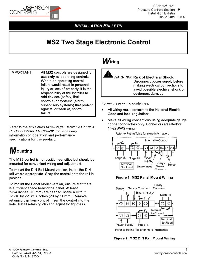
Illustration 4: COM1 (RS232) Pinout.
R S
C S
1
2
3
4
5
6
7
8
9
G
-
RxD
xD

SGC
3.2 COM2/3 PORT
COM2/COM3 ports allow the connection to other telecontrol equipment with a PROCOME or MODBUS
protocol.
2.1 CONFIGURATION
he settings of this port are fully configurable as described in the “Communication Settings” section on
the “General configuration” chapter.
2.2 PROTOCOL AND CONNECTIONS
On 1 P and 2 P models, the connection with the other equipment is run over a serial RS485 link. An
RJ45 connector is used.
Connection can be configured either half-duplex or full-duplex, depending on the setting of internal
jumpers. Default mode is half-duplex.
11 EDP 00110E4
Illustration 5: COM2/3 (RS485) Pinout
(User looking to the female connector shown)
8
1
1 – RX +
2 – RX -
4 – TX -
5 – TX +
8 – GND

4 COMMUNICATIONS FOR SGC195 DEVICES
4 COMMUNICATIONS FOR SGC1 5 DEVICES
he SGC1 5 device has the R U unit iGRID T&D iRTU integrated. It has an Ethernet port and until two
communication independent ports ready to connect to the control center and/or others devices.
Furthermore it has a maintenance port miniUSB and other for USB keys.
Communications configuration of the device can be as follows and each available ports will be:
COM1 COM4 ETH miniUSB
1TP
2TP
Table 4: Available ports in the SGC195 devices.
4.1 COM1 PORT
COM1 is a RS232(modem RS232)/RS422/RS484 software configurable port with 3kV isolated that
connects the SGC195 device with the either control center or other communication devices.
1.1 PROTOCOL AND CONNECTIONS
Data transmission to the control center can be configured by using any of the following protocols:
•IEC60870-5-101
•DNP3.0
•Modbus R U.
In addition it can be connected to a communicable device by using any of the next protocols:
•IEC60870-5-101
•Modbus R U
•DLMS
•Procome.
o connect with the communication COM1 unit a connector Phoenix Contact model MC1.5/9-G-3.5 of 9
contacts is used with the next configuration:
00110E4 EDP 12

SGC
Pin Mode RS232 Mode RS422/
RS485
1 Rx Rx+
2 C S Rx-
3 x x-
4 R S x+
5 GND GND
6 DSR
7 DCD
8 D R
9 RI
Figure 6: COM1 connector pinout (RS232/RS422/RS485)
(User looking to the female connector shown)
o work with protocols using RS232 modem mode a connector Phoenix Contact MC 1,5/9-S -3,5 will be
used. Whereas the protocols using either RS422 or RS485 modes they will use a connector Phoenix
Contact MC 1,5/5-S -3,55
5 his connector is the same as used in COM4 port at chapter 4.2.2.1
13 EDP 00110E4
19

4 COMMUNICATIONS FOR SGC195 DEVICES
4.2 COM4 PORT
he COM4 port is a RS485 port isolated 3kV that allows the SGC195 device to connect with other
devices with serial communications.
2.1 PROTOCOL AND CONNECTION
COM4 can be used to communicate with other devices by means of the next protocols:
•PROCOME
•MODBUS.
o connect with the communication COM4 unit a connector Phoenix Contact model MC1.5/5-G-3.5 of 5
contacts is used with the next configuration:
Pin Mode RS422/
RS485
1 Rx+
2 Rx-
3 x-
4 x+
5 GND
Figure 7: COM4 connector pinout (RS232/RS422/RS485)
(User looking to the female connector shown)
o work with protocols using either RS422 or RS485 mode a connector Phoenix Contact MC 1,5/5-S -
3,5 will be used.
00110E4 EDP 14
15

SGC
4.3 ETHERNET PORT
he Ethernet port is type 10/100 with a RJ45 connector that allows to SGC195 device to connect to the
control center by means a IP network6.
3.1 PROTOCOL AND CONNECTION
he Ethernet port allows a remote connection with either a control center or another device
communicable by means of a network IP by using any of the following protocols:
•IEC60870-5-104
•Modbus CP
•Serial Protocols indicated at the chapter 4.1.1.1 and encapsulated in CP.
3.2 MAINTENANCE THROUGH FTP
his port communicates directly to the integrated R U and allows to do R U maintenance operations
through F P.
o gain access through F P to the R U we will use the current SGC195 device IP address (indicating
user: isupport and password: irtusupport) in your F P manager.
Furthermore Ethernet port allows to do SGC195 device maintenance and commissioning operations by
connecting a computer through Ethernet port (ETH) and using qtAjustes software.
For further information refer to the Commissioning manual.
4.4 MINIUSB PORT
he frontal maintenance port miniUSB allows to connect a computer to the SGC195 device to do
maintenance operations7.
4.1 MAINTENANCE THROUGH FTP
o do local maintenance tasks to the SGC1958 device connecting a computer to the USB_O G (MGMT)
port, computer Windows®9 installed driver will be used. When Windows doesn’t installs correctly the
driver iGrid_iRTU_driver.inf will need to be installed to the computer.
o gain access through F P to the R U we will use the current SGC195 device IP address (indicating
user: isupport and password: irtusupport) in your F P manager10.
With the computer connected to the USB O G (MGMT) port and using the qtAjustes11 software is
possible to do maintenance and commissioning operations to the switchgear control unit12.
For more detailed information refer to the Commissioning manual13.
6 By default the configured IP address in the Ethernet port is 1 2.168.1.100
7 he IP address of the maintenance port MGMT is always 10.10.10.100.
8 his concerns the maintenance ops from switchgear control unit and remote terminal unit.
9 It has been tested with Windows® XP SP3, Windows® Vista, Windows® 7 and Windows® 10.
10 By default the configured RTU maintenance port is 23 (F P).
11 his software can be downloaded from Support → Download Software from Electrónica Digital de
Protección S.A. webpage. Either Sign in or Login is mandatory.
12 By default the configured switchgear control unit maintenance port is 10002.
13 his manual can be downloaded from Support → Download User Manuals from Electrónica Digital de
Protección S.A. webpage. Either Sign in or Login is mandatory.
15 EDP 00110E4
This manual suits for next models
3
Table of contents