Mount
1-Turn the siren upside-down to open the cover, push the 'M' latch upwards and pull the cover below.
(Figure 1)
2-Mark the screw holes and suspender places on the wall with the aid of box bottom plastic or template on
the package for mounting. (Figure 2)
3-Set the electricity connections of the card as shown in Electricity Connections/Figure:9 and draw
attention to the sample Panel Connection section.
4-Place the battery to the slot shown in Figure 3. Be careful with the polarities and the direction of the
battery. (a battery, fix it with the cable bound and open-circuit the Jp1)
5-After completing the electricity and battery connections, place the transparent protection cover on the
card. (Figure 4)
Opening The Top Cover Before Mounting
Attaching the Top Cover
Opening The Top Cover After Mounting
38
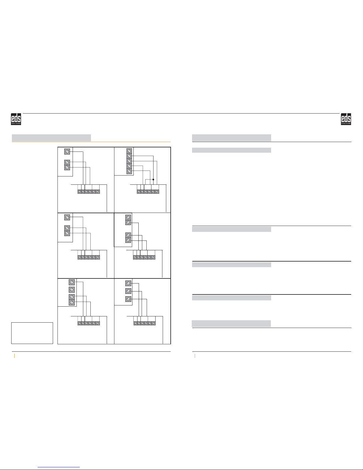
Panel Connections
68
GENERAL
SS
S- S-
S+ S+
ST8048
CLASSIC
+SİREN- 12
PREMIER 412/816
POS COM AUX1
CADDX NX-4/6/8
VERÝTAS 8/8R
SDCA
B
Siren
trigger
Flasher
trigger
-12 V +
- 12V + SAB
SI
FL
Flasher Trigger
- 12V + SAB
SI
FL
Siren Trigger
- 12V + SAB
SI
FL - 12V + SAB
SI
FL
- 12V + SAB
SI
FL - 12V + SAB
SI
FL
CADDX NX 4/6/8 AUX1 programmer:
(Prg. input)
(Location(Menu) NO)
(Prg. Output options)
(outrput active 0-.255min.)
(Prg. Output)
*897130#
47 #
7*
max.0 - 255dk
*46#1***EXIT
Flasher Trigger
Siren Trigger
Flasher Trigger
Siren Trigger
Flasher Trigger
Siren Trigger
Flasher Trigger
Siren Trigger
Flasher Trigger
Siren Trigger
Place the 'A' nails as they would fit into the 'B' holes as shown in Figure:7 and then make the latch be
attached to 'M' point by pressing the top cover.
Push 'M' latch in Figure:7 with a straight screw and lift the top cover. Push the cover upwards to let the
'A' nails release and remove the cover.
Mount the optionally provided metal cover as shown in Figure:8.
Mounting the Metal Cover
1- It should be at least 5cm below the ceiling in order to be able to open the top cover during assembly.
2- Choose a clean and smooth surface for easy mounting.
3- Use 4 units of M4+52 metal screw and M8 dubel(plastic screw holder in-wall)
Important Mounting Notes
OUTDOOR SOUNDER
AS 240 AS 240
OUTDOOR SOUNDER