EDWANZ group Deutronic DBL-MPC4 Series User manual

Deutronicstr. 5, D - 84166 Adlkofen, Germany
Tel.: +49 (0) 8707 920-0
Fax: +49 (0) 8707 1004
http://www.deutronic.com
DBL Operating Instructions / MPC4 Last updated: 03.12.2020 Page 1 of 26
Manual
- Valid from firmware v1.41.251 -
Deutronic Battery Charger / External Power Supply
with MPC4-Board and nominal 14VDC Charging Voltage
(suitable for 12VDC Vehicle On-board Networks and Batteries)
Important note: Do not use the charger in applications for which the device was not
originally designed! Only qualified personnel are allowed to use this
charger. Read operation instructions carefully! In any case pay
attention to the safety instructions and follow the guidelines of the
battery manufacturer!

Deutronicstr. 5, D - 84166 Adlkofen, Germany
Tel.: +49 (0) 8707 920-0
Fax: +49 (0) 8707 1004
http://www.deutronic.com
DBL Operating Instructions / MPC4 Last updated: 03.12.2020 Page 2 of 26
Content
1.
Installation and Safety Instructions ......................................................................3
2.
Device Information .................................................................................................3
2.1.
Device description .................................................................................................3
2.2.
Technical Data.......................................................................................................3
2.3.
Unpacking..............................................................................................................3
2.3.1.
Control on product completeness and transport damage ................................3
2.3.2.
Warning signs on the DBL housing..................................................................4
2.3.3.
Waste disposal of packaging material .............................................................4
2.3.4.
Storage ............................................................................................................4
3.
Connections and Control Elements......................................................................5
4.
Commissioning.......................................................................................................6
5.
Instructions .............................................................................................................8
5.1.
Overview of the menu structure.............................................................................8
5.2.
General notes on operation ...................................................................................9
5.3.
Main Screen ..........................................................................................................9
5.4.
Pin lock ................................................................................................................10
5.5.
Configuration menu .............................................................................................10
5.5.1.
Selection of operation mode ..........................................................................11
5.5.2.
Selection of language ....................................................................................11
5.5.3.
Supply Menu (parameters for the SUPPLYMODE) .......................................12
5.5.4.
Charge Menu (parameters for the CHARGEMODE) .....................................13
5.5.5.
Charge Menu / Features................................................................................15
5.5.6.
Device Menu..................................................................................................16
6.
Operation Mode / Status / Error Messages.........................................................20
7.
Short Cell Detection - instructions for application ............................................22
8.
Signalling / LED and Signal Lamp.......................................................................23
9.
Characteristic Curves...........................................................................................24
10.
Maintenance Instruction ......................................................................................25
11.
Service Centre / Repairs ......................................................................................25
12.
Exclusion of liability.............................................................................................26
13.
Contact ..................................................................................................................26

Deutronicstr. 5, D - 84166 Adlkofen, Germany
Tel.: +49 (0) 8707 920-0
Fax: +49 (0) 8707 1004
http://www.deutronic.com
DBL Operating Instructions / MPC4 Last updated: 03.12.2020 Page 3 of 26
1. Installation and Safety Instructions
In addition to the operating instructions, always also comply with the specifications of the battery
manufacturer, the associated installation and safety instructions and the device-specific data sheets.
The installation and safety instructions, as well as the data sheets, can be found on our website
at
www.deutronic.com
. Alternatively, please contact Deutronic Elektronik GmbH or one of our worldwide
service centers
2. Device Information
2.1. Device description
The battery chargers of DBL-MPC4 series are designed for industrial applications,
especially for the automotive sector. They are used for charging and external power supply
operation. Due to their perfect on-board electrical system suitability, the on-board electrical
system and airbags are protected. Including extensive protection and self-protection
features like short circuit detection, revers polarity protection and a reliable sparks
suppression risks in handling are minimized. A simple menu navigation, configurable
charging parameters and built-in communication interface enable an easy and efficient
use.
2.2. Technical Data
For detailed technical data like input voltage, required mains fuse / automatic
circuit breaker to be used etc. see respective data sheet that you can get on our
webpage www.deutronic.com or on request from Deutronic.
2.3. Unpacking
2.3.1. Control on product completeness and transport damage
The consignment has to be inspected immediately after receipt of the goods for damages
in transit. In case of any damage please inform the carrier promptly for this case it is not
allowed to put the DBL into operation.
Deutronicstr. 5, D - 84166 Adlkofen, Germany
Tel.: +49 (0) 8707 920-0
Fax: +49 (0) 8707 1004
http://www.deutronic.com
DBL Operating Instructions / MPC4 Last updated: 03.12.2020 Page 4 of 26
2.3.2. Warning signs on the DBL housing
Please read the instructions carefully
Warning of hot surfaces
2.3.3. Waste disposal of packaging material
Please keep the packaging material for a possible refuse. If that is not possible please
make sure that the disposal of the packaging material will be in an appropriate and
environmental friendly way with considering the current environmental directives.
2.3.4. Storage
Due to an inappropriate and improper storage the battery charger might be damaged.
-Please protect the battery charger in storage against any dirt, moisture and extreme
temperatures.
-In case of a long-term storage please check the normal functionality before use.

Deutronicstr. 5, D - 84166 Adlkofen, Germany
Tel.: +49 (0) 8707 920-0
Fax: +49 (0) 8707 1004
http://www.deutronic.com
DBL Operating Instructions / MPC4 Last updated: 03.12.2020 Page 5 of 26
3. Connections and Control Elements
1
Mains power switch ON/OFF
2
Connection for power cord with mains connector (AC IN)
3
"+" Plug for POSITIVE charger cable (red clamp)
4
"-" Plug for NEGATIVE charger cable, ground (black clamp)
5
UP - Button (select / edit parameter)
6
ENTER - Button (activate parameter for editing / enter parameter)
7
DOWN - Button (select / edit parameter)
8
Communication interface (9-pole)
9
Signal interface (25-pole)
10
LC Display (display operating status / configuration menu)
11
LED1-3: Signaling operation state
(see chapter 8 Signaling / LED and Signal Lamp)
Deutronicstr. 5, D - 84166 Adlkofen, Germany
Tel.: +49 (0) 8707 920-0
Fax: +49 (0) 8707 1004
http://www.deutronic.com
DBL Operating Instructions / MPC4 Last updated: 03.12.2020 Page 6 of 26
4. Commissioning
-Before taking the charging computer into operation check the charger and the
equipment like the mains supply cord charging cable / clamps or optional accessories
(e.g. external signal lamp) on any damages.
-For taking the charging computer into operation it has to be connected via the power
cable with a suitable mains supply (required data for the regarding device you will find
on the nameplate or the according data sheet).
-Please check the proper fitting of the connected cables.
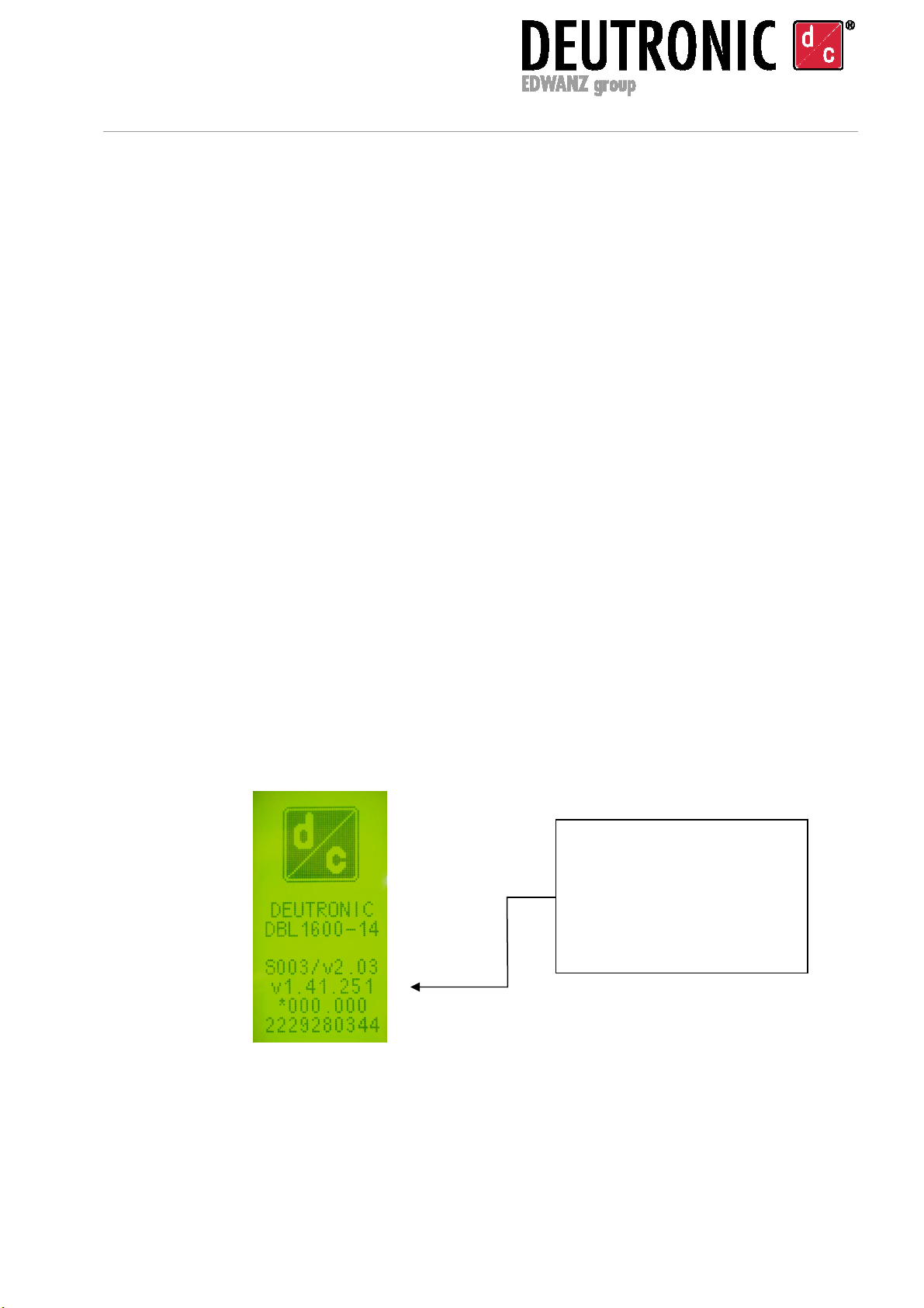
-After turning on the device via the power switch the display shows the version
information for 3 seconds (see Picture 1). When showing you the information you can
choose between the following functions:
a) ‘ENTER’ button: The appearance of the application information can be extended to
30 seconds by pushing the ‘ENTER’ button for at least 3 seconds.
b) ‘UP’ button: When pressing the ‘UP’ button permanently while the version
information will be displayed the language menu will be displayed afterwards. If
necessary the ‘default’ language version can be changed.
Picture 1 – starting screen showing version information of the device
Version information e.g. name of
the device, boot loader/firmware
version
[*]
, parameter set or serial
number of the device.
[*] The text shown depends on
possible customized delivery

Deutronicstr. 5, D - 84166 Adlkofen, Germany
Tel.: +49 (0) 8707 920-0
Fax: +49 (0) 8707 1004
http://www.deutronic.com
DBL Operating Instructions / MPC4 Last updated: 03.12.2020 Page 7 of 26
-After showing the version information or after language selection the display changes
automatically to the main screen (see chapter 5.3 Main Screen).
-The desired line can be selected with the Up / Down buttons in the main screen.
Selecting START activates the load detection circuit and with a valid load connected -
depending on the pre-set mode - SUPPLYMODE or charging mode will be started (the
particular operation mode is shown via LED 1-3; see chapter 8 Signalling / LED and
Signal Lamp).
The supply of the load or the charging process will be stopped and the load detection
will be deactivated by pressing the ‘STOP’ button.
-Additional to the display the operating status of the charger can be displayed via LED
1 to 3 or with a powerful glowing external signal lamp option (on request). Further
information regarding accessories you will find under www.deutronic.com.
-Beside the optical signalisation it is possible to show the operating status of the
charger with the help of an external control (e.g. PLC). Therefore three potential-free
relays are available on the 25 pole interface. Also through this interface you can use a
remote OFF function as further option.
Further details regarding all available interface functions and the optional software
tools from Deutronic for updates, configuration and diagnostic tasks you will get on
request via Deutronic.

Deutronicstr. 5, D - 84166 Adlkofen, Germany
Tel.: +49 (0) 8707 920-0
Fax: +49 (0) 8707 1004
http://www.deutronic.com
DBL Operating Instructions / MPC4 Last updated: 03.12.2020 Page 8 of 26
5. Instructions
5.1. Overview of the menu structure
Note: The parameters and functions in detail will be described in the following chapters.
Main Screen
START / STOP MENU
Information display
- Measurement
(voltage U[V]
or current I[A])
- Status / errors
- Active mode DEVICE
MENU
CHARGE
MENU
SUPPLY
MENU
Operation
Modes
Language
Menu
AUTOMODE
SUPPLYMODE
CHARGEMODE
- U
-
I
max
DEUTSCH
ENGLISH
ESPANOL
FRANCAIS
ITALIANO
- BFL display
- I
BFL
- BFL lock
- T
BFL
-
Short cell
Display VersionCableSafetyAutostopMan.startParameterStorage
- U
max
- U
srt
- Short circuit-
behaviour
- T
del
- Cable resistance
- Automatic
compensation
AUTOSTOP
MAN.STOP
AUTOSTART
MAN.START
- Sleep Mode
- Signal (Chapter 8)
- Key lock
- Code
OFF
CYCLIC
Default
User
FEATURES
U U
tri
U
min
I
max
I
tri
I
re
Q
max
T
min
T
max
NOTE: Depending on possible customized (delivery) specifications a pin
code request can be faded in.

Deutronicstr. 5, D - 84166 Adlkofen, Germany
Tel.: +49 (0) 8707 920-0
Fax: +49 (0) 8707 1004
http://www.deutronic.com
DBL Operating Instructions / MPC4 Last updated: 03.12.2020 Page 9 of 26
5.2. General notes on operation
Should a parameter be changed by the user, it can be selected with the UP / DOWN
buttons at the device and activated for editing by means of the ENTER button. When a
parameter value flashes, it is able to be edited with the UP / DOWN buttons. When
pressing the ENTER button again the new adjusted value is accepted.
Due to safety reasons some parameters (e.g. changing the operation mode like
AUTOMODE, SUPPLYMODE, and CHARGEMODE etc.) cannot be configured when the
charging computer is in operation (load detection is activated or SUPPLYMODE or
CHARGEMODE). For this purpose the active operation has to be deactivated by selecting
’STOP‘.
5.3. Main Screen
Picture 2 – main screen
- Screen display ‘START / STOP’ changes depending on the operation mode.
•Display ‘START‘: DBL is on standby and can activate the load detection circuit
for the displayed operation mode (AUTO, SUPPLY or CHARGEMODE) by
selection of ‘START‘ (pressing the ENTER button). The process will be started
by recognized and valid load.
•Display ‘STOP‘: Device is in an active supply or charging mode or the load
detection of the charger is activated. With the selection of ‘STOP‘ via ENTER
button the supply or charging mode is ended.
-Selecting MENU with pushing ENTER the access to the configuration menu will be
visible. Depending on the active configuration or customized terms of delivery the
access to the menu is protected with a PIN code – see chapters 5.4 and 5.5.
Values:
Voltage U [V]
Current I [A]
Status / error message
Operation mode
Access to configuration menu
START/STOP Function
- STOP: Standby
- START: Load detection active or
load/BAT is energized

Deutronicstr. 5, D - 84166 Adlkofen, Germany
Tel.: +49 (0) 8707 920-0
Fax: +49 (0) 8707 1004
http://www.deutronic.com
DBL Operating Instructions / MPC4 Last updated: 03.12.2020 Page 10 of 26
5.4. Pin lock
The pin lock is activated when you can see the following display (see Picture 3) after
choosing access to the menu. The lock can only be deactivated with entering a predefined
code successfully. Please activate the entry field with the ENTER button, set the code with
the arrow buttons and confirm it with the ENTER button.
Picture 3 – pin lock
Note: The code regarding to the button lock can be activated or predefined in the menu of
the device by the user (see chapter 5.5.6 Device Menu) - or depending on customized
delivery specifications pin code be activated by factory default.
5.5. Configuration menu
By choosing the MENU line on the main screen (see chapter 5.3) the configuration menu
(picture 4) will be displayed. The desired operating parameters can be configured in the
individual menus.
Picture 4 – configuration menu
Selection of current language - see chapter 5.5.2
Configuration menus for ...
SUPPLYMODE (Supply Menu - see chapter 5.5.3)
CHARGEMODE (Charge Menu - see chapter 5.5.4)
General device configuration (Device Menu - see chapter 0)
Selection of operation modes (AUTOMODE, SUPPLYMODE OR
CHARGEMODE) – see chapter 5.5.1
Deutronicstr. 5, D - 84166 Adlkofen, Germany
Tel.: +49 (0) 8707 920-0
Fax: +49 (0) 8707 1004
http://www.deutronic.com
DBL Operating Instructions / MPC4 Last updated: 03.12.2020 Page 11 of 26
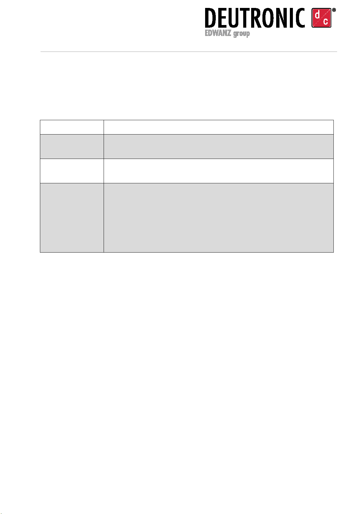
5.5.1. Selection of operation mode
After selecting the operation mode with ENTER field the available modes can be selected
with the arrow buttons and accepted with pressing the ENTER button:
Operation mode Description
AUTOMODE
The charger identifies automatically if a battery or a resistive load is
connected and activates due to this the respective mode.
SUPPLYMODE
It is only allowed to supply a resistive load in the SUPPLYMODE
(e.g. motor vehicle electrical system without connected batteries).
CHARGEMODE
In the CHARGEMODE it is possible to charge the battery built into a
vehicle as well as a standalone battery.
Note:
Only use the charge-mode after all parameters in the charge menu
(see chapter 5.5.4) are configured appropriately to the specifications
of the battery manufacturer.
5.5.2. Selection of language
All available languages are displayed in the LANGUAGE menu item. The language setting
can be changed by selecting the ‘LANGUAGE’ menu item and pushing ENTER with the
help of the arrow buttons it is possible to select the desired language. Afterwards confirm
the selection by pushing ‘ENTER’. Depending on the customized terms of delivery the
languages German, English, Spanish, French and Italian are available in the factory
default settings.
Deutronicstr. 5, D - 84166 Adlkofen, Germany
Tel.: +49 (0) 8707 920-0
Fax: +49 (0) 8707 1004
http://www.deutronic.com
DBL Operating Instructions / MPC4 Last updated: 03.12.2020 Page 12 of 26
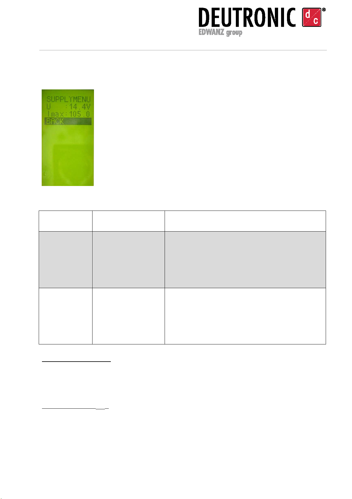
5.5.3. Supply Menu (parameters for the SUPPLYMODE)
Picture 5 – supply menu
[1] Output voltage [U]:
If the chosen voltage is available on the output depends on both the load
conditions in operation and the choice of the OVP limit (see parameter Umax
in chapter 5.5.6 Device Menu submenu “SAFETY”)
[2] Current limit [I
max
]:
If the configured current maximum I
max
is available on the output
depends on
the (load) condition in the operating status. Note: During SUPPLYMODE the
output current limit can automatically be adjusted/reduced via the dynamic
output power and temperature control.
Parameter Description Figures / range of adjustment
U in [V] Output voltage [2 ... 17] V (or max. 20 V on type DBL800-14)
The height of the output current should be
selected so that the connected consumers have
sufficient power. [1]
ATTENTION: Too high voltages can cause
damage on the motor vehicle electrical system!
I
max
in [A] Current limit
Output current
[0 ... I
max
] A
The available maximum value depends on the
power class of the device - see data sheet [2].
ATTENTION: The current limit has to be checked
and if necessary adapted to the connected
equipment (e.g. charging cable and clamps)
Deutronicstr. 5, D - 84166 Adlkofen, Germany
Tel.: +49 (0) 8707 920-0
Fax: +49 (0) 8707 1004
http://www.deutronic.com
DBL Operating Instructions / MPC4 Last updated: 03.12.2020 Page 13 of 26
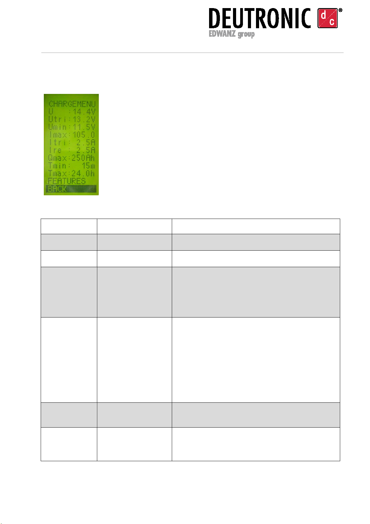
5.5.4. Charge Menu (parameters for the CHARGEMODE)
Picture 6 – charge menu
Parameter Description Figures / range of adjustment
U in [V] Charging voltage [2 ... 17] V (or max. 20 V on type DBL800-14)
U
tri
in [V] Trickle voltage [U
min
... U
charging voltage
] V
U
min
in
[V] Starting voltage [5 … U
tri
] V
Required minimum voltage of the battery - this
defines the voltage limit which must be
exceeded by the battery before starting to
charge [1].
I
max
in [A] Current limit [(I
tri
+ I
re
) ... I
max
] A
The lower limit is dynamic and depends on the
configured values I
tri
and I
re
.
The possible maximum to reach depends on the
power class of the device (see data sheet). [2]
ATTENTION: The current limit has to be
checked and if necessary adapted to the
connected equipment (e.g. charging cable and
clamps)
I
tri
in [A] Trickle charging
current
[1 ... 20] A; Limiting value from which the DBL
switches to trickle charge.
I
re
in [A] Recharge current [0.5 … 30] A; Threshold (Delta-Value) above I
tri
,
from which on the DBL switches back to
CHARGEMODE.

Deutronicstr. 5, D - 84166 Adlkofen, Germany
Tel.: +49 (0) 8707 920-0
Fax: +49 (0) 8707 1004
http://www.deutronic.com
DBL Operating Instructions / MPC4 Last updated: 03.12.2020 Page 14 of 26
Q
max
in [Ah] Maximum battery
charge capacity
[0 … 6000] Ah; Limiting value from which on the
charging process will be stopped with an
application error. The value has to be adapted
depending on the battery to charge or depending
on the (production) process. [3]
T
min
in [min] Minimal charging
time
[0 … 240] minutes; Before a changeover from
charging mode to trickle charging can take place
this time interval has to pass.
T
max
in [h] Maximum charging
time
[0 … 255] h; Maximum time interval after which
the charging process is finished with an
application error [4].
FEATURES Characteristics A new submenu is opened (see chapter 5.5.5).
[1] Starting voltage [U
min
] - SAFETY NOTE:
The starting voltage represents a safety limit. This limit ensures by an
appropriate correct configuration that a technically accurate battery is
connected for the charging process! Information: In the operation mode
AUTOMODE due to safety reasons no batteries are accepted which show
a lower voltage than 11.5 VDC. Nevertheless, if it is necessary to charge a
motor vehicle battery with a lower voltage, please switch from AUTOMODE
in the operation mode CHARGEMODE.
[2] Current limit [I
max
]:
If the configured current maximum Imax is available on the output
depends on the (load) condition in the operating status. Note: During
SUPPLYMODE the output current limit can automatically be
adjusted/reduced via the dynamic output power and temperature control.
[3] Maximum loading quantity [Q
max
]:
Hint for a complete charge of the battery without parallel electrical
consumers: Rise the limit value in the setup configurations round 10…20%
than nominal given for the battery capacity by the battery manufacturer.
Please note: The behaviour of the device when achieving the safety
threshold depends on customized terms of delivery (e.g. switch off output
current, limitation of charging voltage to U
tri
or no reaction if these
parameters were predefined by terms of delivery).
[4] MAXIMUM CHARGING TIME [T
max
]:
Please note: The behaviour of the device in achieving the safety threshold
depends on customized delivery conditions (e.g. switching off output
current, limiting charging voltage to Utri or to no reaction, if these
parameters were defined by terms of delivery).
Deutronicstr. 5, D - 84166 Adlkofen, Germany
Tel.: +49 (0) 8707 920-0
Fax: +49 (0) 8707 1004
http://www.deutronic.com
DBL Operating Instructions / MPC4 Last updated: 03.12.2020 Page 15 of 26
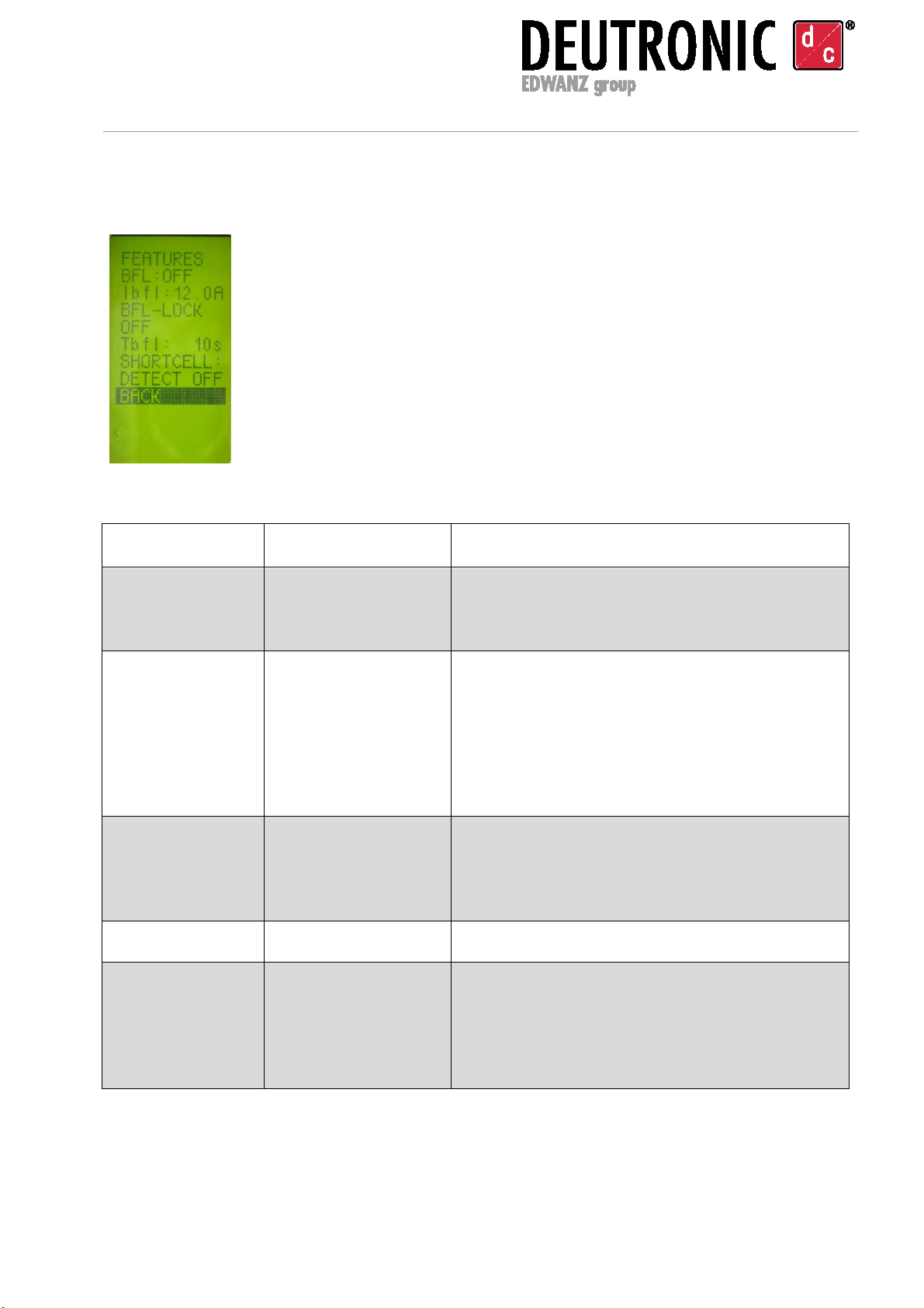
5.5.5. Charge Menu / Features
Picture 7 – features in charge menu
Parameter Description Figures / range of adjustment
BFL (ON/OFF) Signal ‚Battery full‘
activated /
deactivated
Note: BFL signal only takes place after
expiration of T
min
and is in addition
independent from ‘Tri’ settings.
I
bfl
in [A] Current limit at
which BFL is
signaled
BFL signalization is indicated via LED and
connected to an external signal lamp when
the output current is below I
bfl
(see chapter 8).
ATTENTION: If BFL LOCK is deactivated the
BFL signal will be reset as soon as the output
current increases.
BFL-LOCK
(ON/OFF)
Delay time T
bfl
for
BFL-Signal
After current is below I
bfl
and the timer T
bfl
has
expired, then the BFL status signal is
permanent on (until the connected battery is
disconnected or error message displayed).
T
bfl
in [s] Signal delay [1 ... 60] sec
Short cell detect
(ON / OFF)
Battery test It is checked if the battery is showing a fail on
beginning of charging process (Important:
Please follow the instructions in chapter 7
Short Cell Detection - instructions for
application).
Deutronicstr. 5, D - 84166 Adlkofen, Germany
Tel.: +49 (0) 8707 920-0
Fax: +49 (0) 8707 1004
http://www.deutronic.com
DBL Operating Instructions / MPC4 Last updated: 03.12.2020 Page 16 of 26
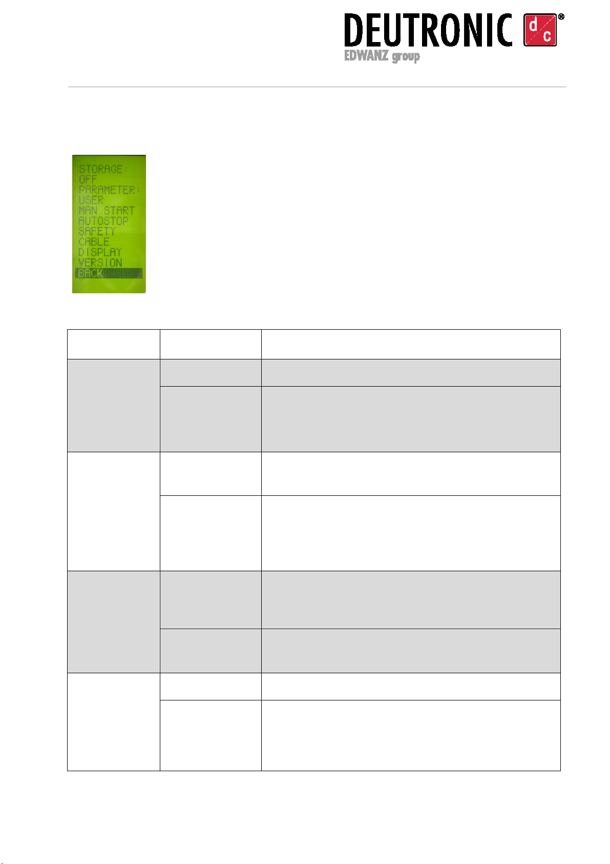
5.5.6. Device Menu
Picture 8 – device menu
Parameter Options Figures / range of adjustment
STORAGE OFF No temporary saving of the charging process state.
CYCLIC Every 5 minutes relevant operating parameters such
as operating modus or timer values are saved and
reactivated after mains power returns. [1]
PARAMETER Default Factory-made standard settings for the operating
parameters of the charger are activated.
User When changing the factory settings the display ‘user’
appears.
Note: On the main screen (refer to Picture 1) you
can see ‘*’ in front of the parameter set number.
MAN. START AUTOSTART The predefined operating mode starts automatically
after network return during recognition of load or
battery.
MAN. START The user starts the device manually with the start
button on the main screen (see chapter 5.3).
AUTOSTOP AUTOSTOP Safety shutdown is activated for Q
max
or T
max
.
MAN. STOP ATTENTION - Switching-off at Q
max
/ T
max
limit is
deactivated! End of supply only takes place after
load is disconnected, after choosing the stop
function in the main menu or via external control. [2]

Deutronicstr. 5, D - 84166 Adlkofen, Germany
Tel.: +49 (0) 8707 920-0
Fax: +49 (0) 8707 1004
http://www.deutronic.com
DBL Operating Instructions / MPC4 Last updated: 03.12.2020 Page 17 of 26
SAFETY U
max
(maximum
output voltage
OVP)
[15.5 / 17
(*)
] V; Important: Follow instructions out [3]!
15.5V: OVP limit 15.5V is active
17.0V
(*)
: OVP limit 15.5V is deactivated
(*)
Note: Max. 20 V on type DBL800-14
U
srt
(Short circuit
voltage) [0 … 13.9] V; If the voltage on the output drops
below the pre-set value, so a short circuit is
recognized and the output relay of the charger will
open.
Important: Follow safety instructions [4]!
LIMITING
PULSING
If an overload or short circuit is recognized (the
voltage on the output drops below U
srt
) then the
device offers two ways to limit the current:
Limiting [5] / pulsing [6]
T
del
(Switch on
delay time)
1 … 60 sec
Note: Switch on delay is working for both - normal
start-up or start-up via external control system.
CABLE R in [Ω]
0 ... 0.250 ohm
Displays resistance value for cable compensation
(can be configured manual).
START
(autom. cable
compensation)
During an ongoing automatically cable
compensation [7] the display switches to STOP (with
pressing the ENTER button the process can be
stopped).
DISPLAY SLEEPMODE
(ON / OFF)
If the SLEEPMODE is ACTIVATED the display
switches after about 1 min of no user action on the
DBL into SLEEPMODE. Note: Useful if the operation
state should only be signalized via the DBL signal
LEDs or with an external signal lamp.
SIGNAL (0-9) Pre-set signalization modes for LED1-3 and external
signal lamp (see chapter 8).
Key lock
ON / OFF
Activate / deactivate pin code to limit access to the
user menu.
CODE
0000 … 9999
Pin code for key lock (e.g. factory-made delivery pre-
set or can be defined by the user).
VERSION Shows detailed version information (e.g. firmware,
parameter set and the serial number of the device).
Deutronicstr. 5, D - 84166 Adlkofen, Germany
Tel.: +49 (0) 8707 920-0
Fax: +49 (0) 8707 1004
http://www.deutronic.com
DBL Operating Instructions / MPC4 Last updated: 03.12.2020 Page 18 of 26
[1] CYCLIC STORAGE - NOTE:
If during a charge process the voltage supply of the charger is interrupted,
then the battery charging is continued automatically at setting STORAGE
CYCLIC as soon as the mains supply is back again (all meter readings, e.g.
previous ampere hours, are further updated).
[2] MAN. STOP – SAFETY NOTE:
ATTENTION! The protective safety shut-down of the charger at the safety
limit (Ah-limit, maximum charging time) is deactivated at MAN. STOP.
[3] MAXIMUM VOLTAGE U
MAX
– SAFETY NOTE:
ATTENTION! The limiting value for maximum voltage 15.5V is an OVP
SAFETY LIMITATION for protecting the electrical system of the motor vehicle
from harmful overvoltage! The 15.5 V safety threshold limits on the one hand
higher parameterized charge and supply output voltage values and on the
other hand the safety threshold limits when an active cable compensation in
process would cause an output voltage over the limit.
Note: The safety threshold can be deactivated (e.g. when a huge voltage
drop on the cable clamps occurs and through cable compensation 15.5 V are
needed). Information: For controlling the output voltage the main screen (see
5.3) shows the actual voltage at any time.
[4] SAFETY U
SRT
– SAFETY NOTE:
The charger is able to recognize a short circuit automatically and is thereby
able to charge the output current down if a prescribed voltage wave (short
circuit voltage U
srt
) was fallen short of in the operating state on the output of
the device. The short circuit voltage – parameterised in the menu has to be
checked in consideration of a voltage drop relating to the connected charging
cables. The voltage has to be adjusted to the resistance of cable clamps and
max. output current of the device in case of need! Attention: Cable clamps
perish in operation due to this their resistance increases. Therefore, please
include a wide safety margin for short circuit nominal voltage!
Example of determining the short circuit nominal voltage ‚U
SRT
‘:
a) In the course of implementation of the cable compensation [7] a resistance value of 15
mOhm was determined for the connected charging cable.
b) The maximum output current of the charger is 100A.
c) Calculation of the voltage drop ∆U = 0.015 Ohm * 100A = 1.5V
d)
Definition of short circuit voltage: The short circuit voltage has to be configured with a
proper distance from the calculated voltage drop for a safe switch-off (because of the
aging process of the cable, contamination mechanical tongs in operating state or
enhanced contact resistance at contact points).
For the present case a value of 5.0V can be configured.

Deutronicstr. 5, D - 84166 Adlkofen, Germany
Tel.: +49 (0) 8707 920-0
Fax: +49 (0) 8707 1004
http://www.deutronic.com
DBL Operating Instructions / MPC4 Last updated: 03.12.2020 Page 19 of 26
[5] SECURITY LIMITING - OVERLOAD OR SHORT CIRCUIT BEHAVIOUR
If the voltage at the measuring point on the device output drops below U
srt
the
output current will be limited and the output relay will open.
[6] SECURITY PULSING - OVERLOAD OR SHORT CIRCUIT BEHAVIOUR
The output relay will open for 60 seconds if the output voltage drops below
U
srt.
After that time period a new switch-on will be attempted for proofing if the
load can be supplied or the short circuit (or situation of overload) is still
present. In total, the DBL emits three pulses – in case the overload or the
short circuit is still present no more attempts are made until disconnection of
the load or reset of the device.
[7] CABLE - REFERENCE TO THE CABLE COMPENSATION:
Before the cable compensation can be started first select STOP in the main
menu!
To perform the cable compensation the charging cables have to be
connected with the device and furthermore the charging cables have to be
shorted on the free ends (without load) with direct contact at the current-
carrying clamp shoe.
In order to perform the resistance measurement please navigate to the
DEVICE MENU / CABLE, select START item and press the ENTER button -
the cable compensation is now running for about 30 seconds. If the cable
compensation has been performed successfully the measured resistance
value will be shown on the display. The resistance value can also be entered
or changed manually by selecting line “R:” and activating edit function with
ENTER button. The value can be modified with the arrow buttons and finally
selected with the ENTER button.
The measured or configured resistance value is stored and is retained even
after the unit has been switched off.
Please note:
- Depending on the customized terms of delivery the factory-setting regarding
the cable compensation can differ from 0 Ohm!
- If a cable resistance value is disposed the DBL automatically activates the
dynamic short circuit detection (in addition to the U
srt
configuration).
The dynamic short circuit detection function considers R
cable
as well as the
configured I
max
from the selected operation mode and will be activated as
soon as the calculated U
srt-dynamic
> U
srt
.
Deutronicstr. 5, D - 84166 Adlkofen, Germany
Tel.: +49 (0) 8707 920-0
Fax: +49 (0) 8707 1004
http://www.deutronic.com
DBL Operating Instructions / MPC4 Last updated: 03.12.2020 Page 20 of 26
6. Operation Mode / Status / Error Messages
Display Meaning / Reasons Correction
Ah LIMIT Charging process stopped
after the predefined limiting
value (ampere hours [Ah])
has been exceeded.
-Maybe the battery capacity was
adjusted to low in the setup?
Indication for complete charging of
the battery: Switch the limiting
value (Ah) given in the setup for
the charging process
approximately 20% higher than the
manufacturer is declaring for the
battery capacity
-Were possibly parallel consumers
activated during the charging
process?
-The battery might be defective?
CABLE COMP Cable compensation mode is
activated.
-See chapter 5.5.6 Device Menu
CELLCHECK The cell test is running (only
with activated short-cell
detection)
-See chapter 7 Short Cell Detection
- instructions for application
CHARGE The DBL is in operation mode
battery charge.
-Battery is charged
CONTACT
(flashing)
Automatic load detection is
activated (the DBL checks if a
battery or a resistive load is
connected).
-Connect battery or load to the
charger
-Check the connected consumers
on any errors (wrong kind of
battery or external voltage source)
-As the case may be there is a
defective cable (check connection
to the load or battery)
DISCHARGED The voltage of the connected
battery is below U
min
.
-Check battery if it is defective?
-Check the operation mode and the
starting voltage U
min
- see chapter
5.5.4 Charge Menu (parameters
for the CHARGEMODE)
EXT.STOP Operation interrupted via the
Remote OFF signal line.
-Detach GND connection at PIN 25
(Remote OFF)
Table of contents
Popular Batteries Charger manuals by other brands


Knightsbridge
Knightsbridge 12DC36 Installation & maintenance manual

HIKOKI
HIKOKI UC 18YSL3 Handling instructions

NOCO Genius
NOCO Genius Genius 2D User guide & warranty

KUSSMAUL
KUSSMAUL 091-74 instruction manual

Deltran
Deltran Battery Tender Selectable manual

EINHELL
EINHELL BT-BC 2D operating instructions