Edwards HAT1000 Mounting instructions

Safety Instructions Manual
07-2018
Original Instructions - HAT1000-2
EDWARDS

1General
Operator and Supervisor Information
Signal Word Denition
Signal Word Panel
2 Signal Word Panel - Machine Front
3 Signal Word Panel - Machine Back
4Signal Words
Warning Panel
Caution Panel
Notice Panel
Safety Manual Table of Contents
Operator and Supervisor Information
This is one of four manuals supplied with your machine.
• Installation Manual
• Safety Instructions Manual
• Operations Manual
• Maintenance Manual
READ ALL MANUALS BEFORE OPERATING MACHINERY. Operating
machinery before reading and understanding the contents of all four
manuals greatly increases the risk of injury.
Each of the four machine manuals describes ‘best practices’ in han-
dling, installing, operating and maintaining your machine. The contents
of each manual is subject to change without notice due to improvements
in the machinery or changes in National or International standards.
All rights reserved. Reproduction of this manual in any form, in whole or
in part, is not permitted without the written consent of Edwards Manu-
facturing Company.
Keep all manuals close to the machine to allow for easy reference when
necessary.
Provide operators with sufcient training and education in the basic
functions of the machine prior to machine operation.
Do not allow for operation of the machine by unqualied personnel.
Edwards Manufacturing Company is not liable for accidents arising from
unskilled, untrained operation.
Do not modify or change the machine without written authorization from
Edwards Manufacturing Company. Unauthorized modication to a ma-
chine may result in serious operator injury, machine damage and will
void your machine warranty.
Never leave a powered machine unattended. Turn machinery OFF be-
fore walking away.
This machine is manufactured for use by able bodied and able minded
operators only. Never operate machinery when tired or under the inu-
ence of drugs or alcohol.
Do not resell, relocate or export to a destination other than to the original
point of sale. Edwards has designed this machine to meet the stan-
dards of the original receiving country and is not liable for meeting any
governing body or performance standards beyond those of the original
receiving country.
Signal Word Definition
Indicates a hazardous situation that, if not avoided,
will result in death or serious injury.
Indicates a hazardous situation that, if not avoided,
could result in death or serious injury.
Indicates a hazardous situation that, if not avoided,
could result in mild or moderate injury.
Indicates information considered important, but not
hazard related.
Signal Word Panel on Machine
Critical machine safety information is identied on signal word labels. La-
bels are attached adjacent to the potentially hazardous locations of the
machine. Reference the Safety Instruction Manual for additional informa-
tion regarding the potentially hazardous condition identied on the label.
Review ALL labels on the machinery, reference the operational pre-
cautions and safe operations sections within this manual before any
operation activity is initiated.
Failure to read and understand the signal word labels afxed to the
machinery may result in operator death or injury.
1
WARNING: This product can expose you to chemicals
including Methyl Isobutyl Ketone which is known to the State of
California to cause cancer and birth defects or other reproduc-
tive harm. For more information go to http://www.p65warnings.
ca.gov.
WARNING: Some dust, fumes and gases created by pow-
er sanding, sawing, grinding, drilling, welding and other construc-
tion activities contain chemicals known to the State of California
to cause cancer and birth defects or other reproductive harm.
Some examples of these chemicals are:
• lead from lead based paint
• crystalline silica from bricks, cement and other masonry
products
• arsenic and chromium from chemically treated lumber
Your risk of exposure varies, depending on how often you do this
type of work. To reduce your exposure to these chemicals, work
in a well-ventilated area and work with approved safety equip-
ment, such as dust masks that are specically designed to l-
ter out microscopic particles. For more information go to http://
www.p65warnings.ca.gov/ and http://www.p65warnings.ca.gov/
wood.

2
10 Ton Tube/Pipe Bender • Signal Word Panel
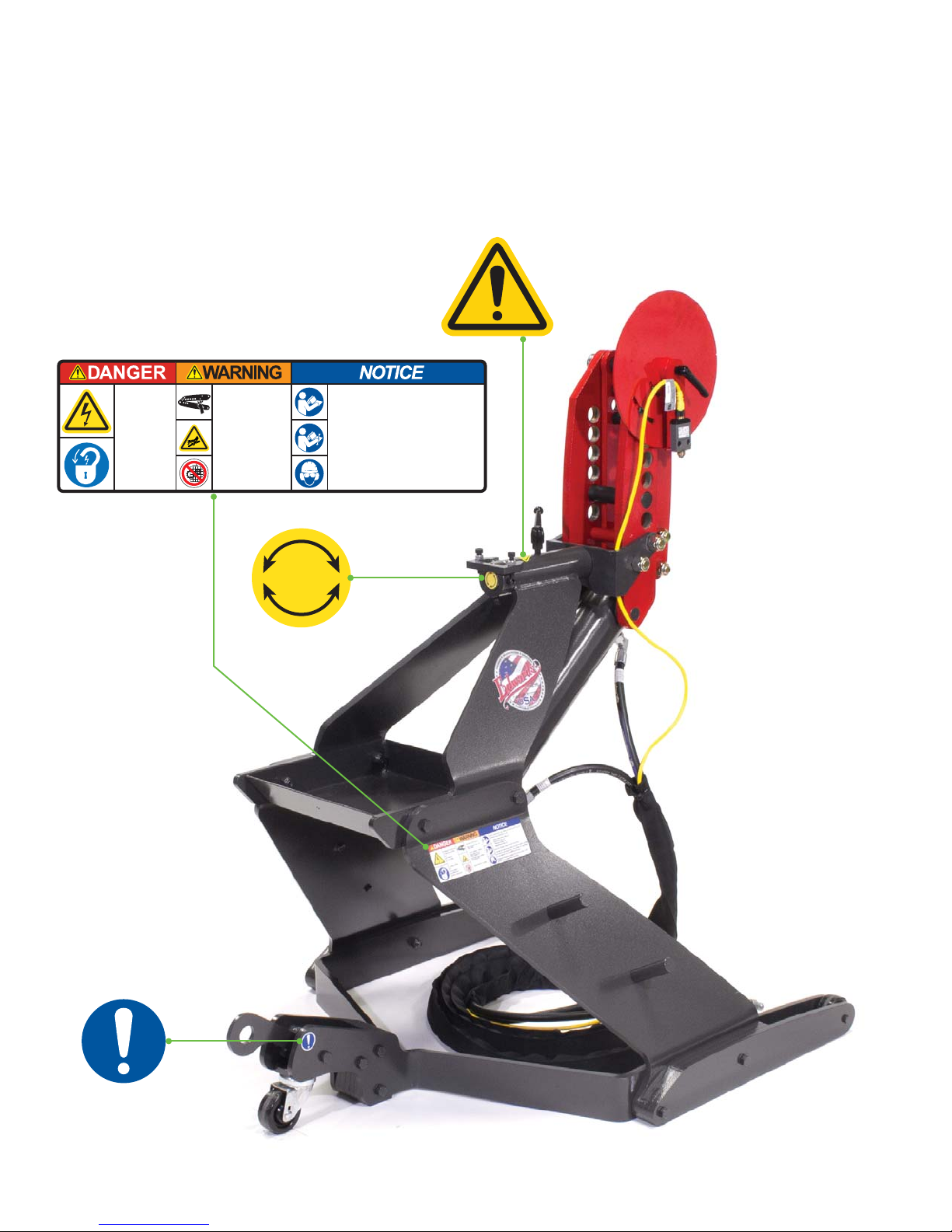
3
10 Ton Tube/Pipe Bender • Signal Word Panel
Hydraulic accessory
controls powered
by
Ironworker/
Porta-Power.
Lockout power
at
Ironworker/
Porta-Power
before servicing.
Shear/Crush Hazard
Moving parts can cut
and crush.
Fluid injection Hazard
Hydraulic fluid is
under pressure.
Hydraulic fluid powers
moving parts.
Keep guards in place
Read, understand, and follow all labels shown on the
machine and described in the:
• Safety Instructions Manual
• Installation Manual
• Operations Manual
• Maintenance Manual
Keep all manuals close for easy reference.
Trained and authorized personnel are to install, operate
and service this machinery. Do not allow for operation
of the machine by unqualified personnel.
Personal protective equipment must be worn at all
times during machinery operation.
4
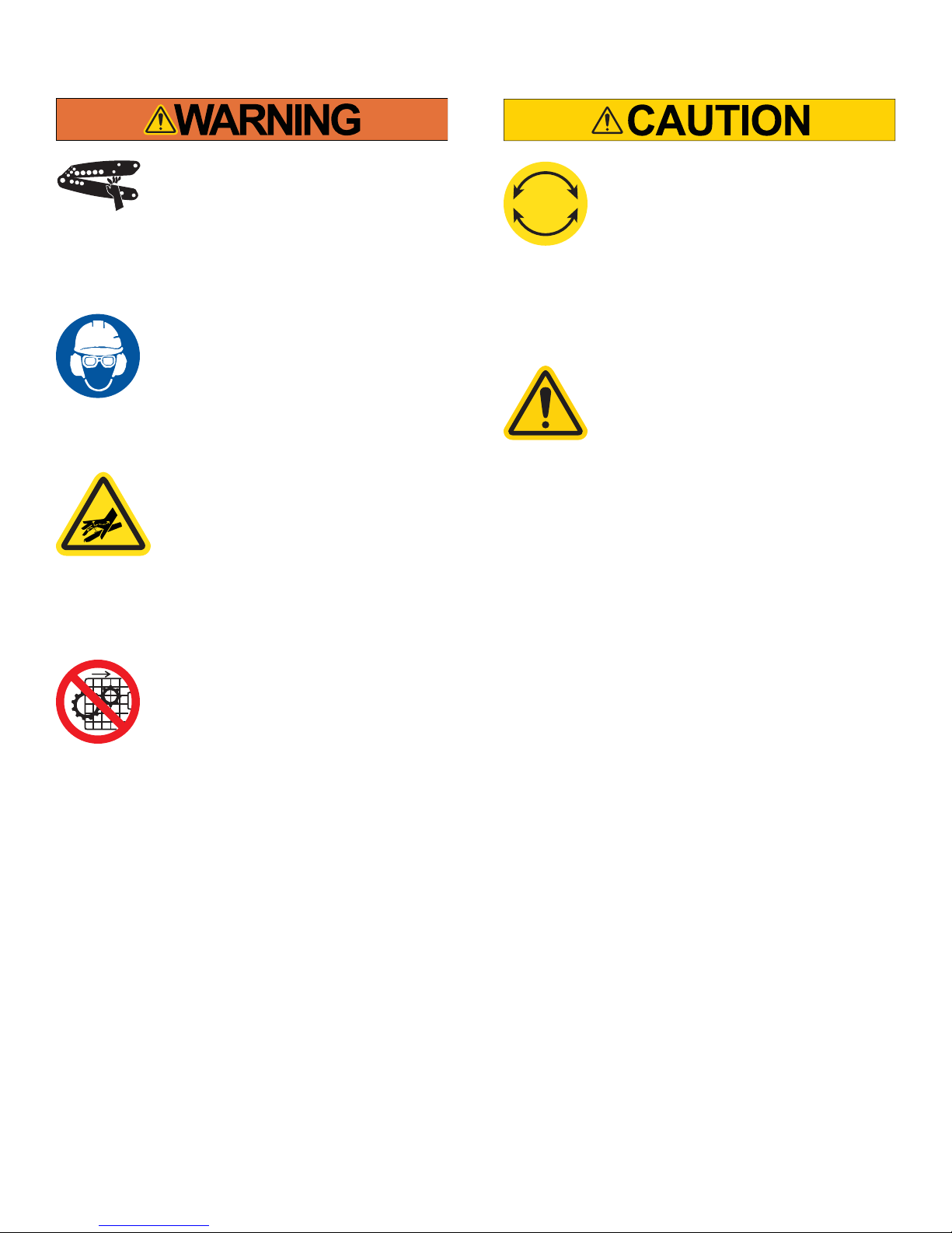
Warning Panel
Shear/Crush Hazard
Moving parts can cut and crush. Keep
hands clear while operating. Lockout
power before servicing. Immediately
replace guards after adjustment, repair or
service.
Wear Personal Protective
Equipment
To avoid physical hazard, always wear per-
sonal protective equipment. Wear protec-
tive eyewear, clothing, gloves, footwear,
head-gear and hearing protection while
operating or servicing this machinery.
Fluid Injection Hazard
Hydraulic hoses and cylinders are under
pressure. Pressurized uid can pierce skin
and cause severe injury. To avoid physical
hazard, always wear personal protective
equipment. Keep hands clear while oper-
ating. Lockout power before servicing.
Immediately replace guards after adjust-
ment, repair or service.
Do Not Operate With Guard
Removed
Physical barriers and guards have been
designed and installed to protect the
Operator from moving parts that can pinch,
cut and crush. Keep hands clear while
operating. Lockout power before servicing.
Immediately replace guards after adjust-
ment, repair or service to moving parts.
Tilting Operation
The bender can be operated in either a
horizontal or vertical position. Exercise
care when changing the operating position
of the bender and during operation of the
bender.
Tilting Operation
The head-frame of your Edwards 10 Ton
Tube/Pipe Bender is mounted with a yoke
and pin to a sleeve and stop mechanism in
the bender stand. This mounting congu-
ration allows for the bender head-frame to
be operated in either a horizontal or vertical
orientation. Exercise care when changing
the operating position of the bender and
during operation of the bender.
Caution Panel

5
Notice Panel
Wear Personal Protective
Equipment
To avoid physical hazard, always wear per-
sonal protective equipment. Wear protec-
tive eyewear, clothing, gloves, footwear,
head-gear and hearing protection while
operating or servicing this machinery.
Refer to All Manuals
Each manual that comes with this machine
contains critical instructions regarding
proper operations, safety, installation and
maintenance procedures. Understand the
contents of each manual thoroughly. Failure
to follow proper procedures may result in
serious operator injury, machine damage
and will void your machine warranty. Keep
the manuals close to the machine for easy
reference.
Bender Operation
Edwards 10 Ton Tube / Pipe Bender machin-
ery is capable of many functions. This
manual outlines the basic functions associ-
ated with typical bender operations and is
neither intended to create a comprehensive
list of, nor describe every operation possible
with a bender tool. Bender operations are
dangerous and require extreme care and
caution in the safe installation, opera-
tion and maintenance of the machin-
ery. Edwards Manufacturing Company
strongly suggests reading and under-
standing all manuals associated with
the machinery as well as obtaining cer-
tied, technical, industrial machinery
operations and maintenance training to
reduce the risk of injury. Regardless of
the contents of the machinery manuals
Edwards Manufacturing Company will
not be held liable for accidents caused
by lack of training.

1107 Sykes St., Albert Lea, MN 56007 800-373-8206 www.edwardsironworkers.com
S
EDWARDS

Installation Manual
07-2018
Original Instructions - HAT1000-1
EDWARDS

1 General
Operator and Supervisor Information
Signal Word Denition
Signal Word Panel
2 Installing the Bender
Environmental Requirements at Work Station
Receiving the Bender
Unpacking/Moving the Bender
3 Hydraulic Power
Powering with an Edwards Ironworker
Powering with an Edwards Porta Power
Installation Manual Table of Contents
Operator and Supervisor Information
This is one of four manuals supplied with your machine.
• Installation Manual
• Safety Instructions Manual
• Operations Manual
• Maintenance Manual
READ ALL MANUALS BEFORE OPERATING MACHINERY. Operating
machinery before reading and understanding the contents of all four
manuals greatly increases the risk of injury.
Each of the four machine manuals describes ‘best practices’ in han-
dling, installing, operating and maintaining your machine. The contents
of each manual is subject to change without notice due to improvements
in the machinery or changes in National or International standards.
All rights reserved. Reproduction of this manual in any form, in whole or
in part, is not permitted without the written consent of Edwards Manu-
facturing Company.
Keep all manuals close to the machine to allow for easy reference when
necessary.
Provide operators with sufcient training and education in the basic
functions of the machine prior to machine operation.
Do not allow for operation of the machine by unqualied personnel.
Edwards Manufacturing Company is not liable for accidents arising from
unskilled, untrained operation.
Do not modify or change the machine without written authorization from
Edwards Manufacturing Company. Unauthorized modication to a ma-
chine may result in serious operator injury, machine damage and will
void your machine warranty.
Never leave a powered machine unattended. Turn machinery OFF before
walking away.
This machine is manufactured for use by able bodied and able minded
operators only. Never operate machinery when tired or under the inu-
ence of drugs or alcohol.
Do not resell, relocate or export to a destination other than to the original
point of sale. Edwards has designed this machine to meet the stan-
dards of the original receiving country and is not liable for meeting any
governing body or performance standards beyond those of the original
receiving country.

Signal Word Definition
Indicates a hazardous situation that, if not avoided,
will result in death or serious injury.
Indicates a hazardous situation that, if not avoided,
could result in death or serious injury.
Indicates a hazardous situation that, if not avoided,
could result in mild or moderate injury.
Indicates information considered important, but not
hazard related.
Signal Word Panel on Machine
Critical machine safety information is identied on signal word labels. La-
bels are attached adjacent to the potentially hazardous locations of the
machine. Reference the Safety Instruction Manual for additional informa-
tion regarding the potentially hazardous condition identied on the label.
Review ALL labels on the machinery, reference the operational pre-
cautions and safe operations sections within this manual before any
operation activity is initiated.
Failure to read and understand the signal word labels afxed to the
machinery may result in operator death or injury.
1
WARNING: This product can expose you to chemicals
including Methyl Isobutyl Ketone which is known to the State of
California to cause cancer and birth defects or other reproduc-
tive harm. For more information go to http://www.p65warnings.
ca.gov.
WARNING: Some dust, fumes and gases created by pow-
er sanding, sawing, grinding, drilling, welding and other construc-
tion activities contain chemicals known to the State of California
to cause cancer and birth defects or other reproductive harm.
Some examples of these chemicals are:
• lead from lead based paint
• crystalline silica from bricks, cement and other masonry
products
• arsenic and chromium from chemically treated lumber
Your risk of exposure varies, depending on how often you do this
type of work. To reduce your exposure to these chemicals, work
in a well-ventilated area and work with approved safety equip-
ment, such as dust masks that are specically designed to l-
ter out microscopic particles. For more information go to http://
www.p65warnings.ca.gov/ and http://www.p65warnings.ca.gov/
wood.

This manual provides installation requirements for the Edwards
10 Ton Tube/Pipe Bender.
ALL EDWARDS HYDRAULIC ACCESSORY TOOLS ARE POW-
ERED BY AN EDWARDS IRONWORKER OR EDWARDS PORTA-
POWER, PORTABLE HYDRAULIC POWER-PLANT.
REFER TO SAFETY, INSTALLATION, OPERATIONS AND MAIN-
TENANCE MANUALS FOR THE EDWARDS POWER-PLANT YOU
ARE USING TO OPERATE YOUR EDWARDS HYDRAULIC ACCES-
SORY TOOL.
Environmental Requirements at Work Station
The work station environment for your Edwards 10 Ton Tube/Pipe
Bender must meet the following minimum requirements:
• Ambient temperature: 7.2°C - 43.3°C [45°F - 110°F]
• Relative humidity: No greater than 90% relative humidity.
• Floor area: Assure that the machinery work area provides
for a stable, adequately sized and load rated oor area for
material movement to and from the machinery work stations.
• Shelter: Protect your machinery from water, salts and cor-
rosive elements.
• Lighting: 500LUX (50 footcandles) minimum.
Receiving the Bender
Edwards Hydraulic Accessory Tools are fully assembled and are shipped
either by palletized custom wooden crate or by shrink–wrapped wooden
pallet for ease of transport and receiving.
Inspect the packaging for damage and follow shipping/receiving instruc-
tions as listed on the packaging prior to receiving the tool into your
facility.
When receiving your Hydraulic Accessory Tool, be prepared to safely
move your machinery with a fork-lift rated for the following equipment
weights:
Minimum Machinery Weights
10 Ton Tube/Pipe Bender 226.79kg/500lb
Utilize best practices for fork-lift operation. Handle material as close
to the drive surface as possible with the widest spread and deepest pen-
etration of forks effective to service the pallet. Forks should be adjusted
and locked into the safety detent closest to the maximum available fork
spread.
Unpacking/Moving the Bender
Your Edwards 10 Ton Tube/Pipe Bender includes surface and remotely
mounted electrical cabling and hydraulic lines. Exercise caution when
removing the factory supplied packaging. Do not cut electrical wires or
hydraulic hoses.
1. Carefully remove the wooden blocking from under the three
wheeled base and carefully roll the tool off of the shipping pallet.
2. Engage the third wheel by pushing the kickstand mechanism down
with your foot. Carefully roll the tool to the workstation.
3. Locate your bender directly adjacent to the Edwards Ironworker or
Porta Power. Ensure that power controls of the Ironworker or
Porta Power are within arms-reach of the bender tool.
Installing the Bender
2

Hydraulic Power
Your Edwards Tube/Pipe Bender is factory assembled and tested for
optimum performance when powered by Edwards Manufacturing Com-
pany rated hydraulic power supplies.
The Bender is powered by either an Edwards Ironworker with the fac-
tory installed Hydraulic Accessory Control Package or an Edwards Porta-
Power, 5hp, 3000psi, portable power unit.
ALTERNATE POWER SOURCES ARE NOT RECOMMENDED
AND MAY COMPROMISE MACHINE OPERATION, MACHINE
HYDRAULIC WARRANTY AND OPERATOR SAFETY.
Follow electrical connection installation instructions for power supply as
set forth within the Installation Manual of the Edwards Ironworker or
Porta-Power.
Powering with an Edwards Ironworker
Power selection controls are located adjacent to the starter on the feed
side of the machine. Hydraulic quick connections and accessory controls
are located on the drop-off side or end cap of the machine.
With the Ironworker power off, install Bender hoses, power and control.
Assure your M12 connections are seated properly. Align M12 male
and female fittings so that keyed surfaces align. Misalignment of
surfaces will prohibit correct operation.
• Install the Bender male and female accessory hydraulic hoses to
the ironworker male and female quick-connect hydraulic fittings.
Both fittings have a detent ball setting that must be aligned to
couple and uncouple hoses.
• Remove the safety cap at the push button port. Attach the Bender
hand control male mil. spec. control cable to the female mil. spec.
accessory control port at your Ironworkers Hydraulic Accessory
package. Attach the yellow limit switch cable to the limit switch
port of the ironworker.
With all Ironworker and Bender stations clear of hands, tools, tool-
ing, material or debris, power up the Ironworker by depressing the
green button on the starter box.
With the power on, your Ironworker machine will return to a neutral
position.
Turn the 3-position switch on the front of the machine case to the Ac-
cessory position. This operation disables the Ironworker and switches
control to the accessory hand control.
Test the Bender operation by pressing the OUT control button. Once
pressed, the cylinder will extend. Releasing pressure on the OUT control
button will stop the cylinder. Test the Bender operation by pressing the
IN control button. Once pressed, the cylinder will be retracted back into
the cylinder enclosure. Releasing pressure on the IN control button will
stop the cylinder.
Test the limit switch by extending the cylinder until the auto stop meets
its positive stop.
Press the red e-stop button to kill power at the Ironworker. To reset
power, twist the e-stop button and push start button at the Ironworker.
When disconnecting your Bender, simply reverse procedure. Replace
the safety cap at the push button port to restore power to your
Ironworker.
Powering with an Edwards Porta-Power
Your Edwards Porta-Power 5hp / 3000psi / Portable Power Unit will
power all your Edwards Hydraulic Accessories.
Follow electrical connection installation instructions as set forth within
these sections of the Installation Manual:
With the Edwards Porta-Power off, install accessory hoses, power and
control. Assure your M12 connections are seated properly. Align
M12 male and female fittings so that keyed surfaces align. Mis-
alignment of surfaces will prohibit correct operation.
• Install the male and female Bender hydraulic hoses to the Porta-
Power male and female quick connect hydraulic fittings adjacent to
the starterbox. Both fittings have a detent ball setting that must be
aligned to couple and uncouple hoses.
• Remove the safety cap at the push button port. Attach the Bender
hand control, male mil. spec. control cable to the female mil. spec.
accessory push button port on the Porta-Power case. Attach the
yellow limit switch cable to the limit switch port of the Porta-Power.
With all Ironworker and Bender stations clear of hands, tools, tool-
ing, material or debris, power up the Porta-Power by depressing
the green button on the starter box.
With the power on, your Bender is in a neutral position.
Test the Bender operation by pressing the OUT control button. Once
pressed, the cylinder will extend. Releasing pressure on the OUT control
button will stop the cylinder. Test the Bender operation by pressing the
IN control button. Once pressed, the cylinder will be retracted back into
the cylinder enclosure. Releasing pressure on the IN control button will
stop the cylinder.
Test the limit switch by extending the cylinder until the auto stop meets
its positive stop.
If the machine fails to cycle, power down the Porta-Power by pressing
the red button on the starterbox, consult the trouble shooting section of
the Operations Manual.
Press the red e-stop button on the hand control to kill power at the Porta
Power. To reset power, twist the e-stop button and push start button at
Porta Power.
When disconnecting your Bender, simply reverse procedure. Replace
the safety cap at the push button port to restore power to your
Porta Power.
3

1107 Sykes St., Albert Lea, MN 56007 800-373-8206 www.edwardsironworkers.com
S
EDWARDS

Operations Manual
Serial Number:
07-2018
Original Instructions - HAT1000-3
EDWARDS

1General
Company Prole
Machine Identication
Warranty
Operator and Supervisor Information
Signal Word Denition
Signal Word Panel
Operational Precautions
Machine Operations
4 Hydraulic Power Sources
Powering with an Edwards Ironworker
Powering with an Edwards Porta-Power
6Operations Diagram
7 Component/Base Operations
Tilting Head-Frame Operation
Base Operation
8Die Set Diagram
9 Die Set Operations
10 Head Frame Diagram
11 Protractor/Auto-Stop Control
Protractor
Auto-Stop Control
12 Bending
Loading Material
Lubrication
Bending
13 Troubleshooting
Operations Manual Table of Contents

1
Company Profile
Edwards Manufacturing Company
manufactures a full line of high
quality, low maintenance hydraulic
ironworking machines, associated
tooling and accessories that are
used in the steel fabrication industry.
With proper operation, care, and
maintenance, your Edwards
Ironworker or Hydraulic Accessory
Tool will provide consistent, long-term service. Please take time
to study this Operator’s Manual carefully to fully understand
Ironworker and Hydraulic Accessory Tool safety procedures,
set-up, operation, care, maintenance, troubleshooting and
warranty coverage prior to putting the machine into production.
Any questions not answered within this manual can be directed
to your local Edwards Ironworker dealer or factory representative.
Contact the factory:
Edwards Manufacturing
Company
1107 Sykes Street
Albert Lea, MN 56007
507 373 8206 PHONE
507 373 9433 FAX
www.edwardsironworkers.com
General Questions:
sales@edwardsmfg.us
Service Questions:
Contact your dealer:
Warranty
Edwards Manufacturing Company will, within one (1) year
of date of original purchase (proof of purchase required),
replace F.O.B. the factory, any goods, excluding punches,
dies and shear blades, which are defective in materials or
workmanship provided that the buyer return the defective
goods, freight pre-paid, to the seller, which shall be the
buyer’s sole and exclusive remedy for the defective goods.
Hydraulic components are subject to their manufacturer’s
warranty.
Edwards Manufacturing Company will, within thirty (30) days
of date of original purchase (proof of purchase required),
replace F.O.B. the factory, any punches, dies and/or shear
blades, which are defective in materials or workmanship.
This warranty does not apply to machines and/or components
which have been altered, changed or modified in any way,
or subjected to abusive and abnormal use, inadequate
maintenance and lubrication, or subjected to use beyond
seller recommended capacities and specifications. Edwards
Manufacturing Company shall not be liable for labor costs
expended on such goods or consequential damages.
Edwards Manufacturing Company shall not be liable to
the purchaser or any other person for loss, down-time, or
damage directly or indirectly arising from the use of the
goods or from any other cause. No officer, employee, or
agent of Edwards Manufacturing Company is authorized to
make any oral representations or warranty of fitness or to
waive any of the foregoing terms and none shall be binding
on Edwards Manufacturing Company.
NOTE: Edwards Manufacturing is a division of JPW Industries,
Inc. References in this document to Edwards also apply to
JPW Industries, Inc., or any of its successors in interest to
the Edwards brand.
Machine Identification
Your Edwards 10 Ton Tube/Pipe Bender has been serialized for quality
control, product traceability and warranty enforcement. Please refer to
the aluminum identification tag with engraved serial number, electrical
and power specifications when ordering parts or filing a warranty claim.
EDWARDS

This is one of four manuals supplied with your machine.
• Safety Instructions Manual
• Installation Manual
• Operations Manual
• Maintenance Manual
READ ALL MANUALS BEFORE OPERATING MACHINERY. Operating
machinery before reading and understanding the contents of all four
manuals greatly increases the risk of injury.
Each of the four machine manuals describes ‘best practices’ in han-
dling, installing, operating and maintaining your machine. The contents
of each manual is subject to change without notice due to improvements
in the machinery or changes in National or International standards.
All rights reserved. Reproduction of this manual in any form, in whole or
in part, is not permitted without the written consent of Edwards Manu-
facturing Company.
Keep all manuals close to the machine to allow for easy reference when
necessary.
Provide operators with sufcient training and education in the basic
functions of the machine prior to machine operation.
Do not allow for operation of the machine by unqualied personnel.
Edwards Manufacturing Company is not liable for accidents arising from
unskilled, untrained operation.
Do not modify or change the machine without written authorization from
Edwards Manufacturing Company. Unauthorized modication to a ma-
chine may result in serious operator injury, machine damage and will
void your machine warranty.
Never leave a powered machine unattended. Turn machinery OFF be-
fore walking away.
This machine is manufactured for use by able bodied and able minded
operators only. Never operate machinery when tired or under the inu-
ence of drugs or alcohol.
Do not resell, relocate or export to a destination other than to the original
point of sale. Edwards has designed this machine to meet the stan-
dards of the original receiving country and is not liable for meeting any
governing body or performance standards beyond those of the original
receiving country.
2
Indicates a hazardous situation that, if not avoided,
will result in death or serious injury.
Indicates a hazardous situation that, if not avoided,
could result in death or serious injury.
Indicates a hazardous situation that, if not avoided,
could result in mild or moderate injury.
Indicates information considered important, but not
hazard related.
Signal Word Panel on Machine
Critical machine safety information is identied on signal word labels. La-
bels are attached adjacent to the potentially hazardous locations of the
machine. Reference the Safety Instruction Manual for additional informa-
tion regarding the potentially hazardous condition identied on the label.
Review ALL labels on the machinery, reference the Safety Instruc-
tions Manual, the operational precautions and the safe operations
sections within this manual before any operation activity is initiated.
Failure to read and understand the signal word labels afxed to the
machinery may result in operator death or injury.
Signal Word DefinitionOperator and Supervisor
Information

3
Edwards Benders are designed to bend solid round, Schedule 40
pipe, tube, square tube, and d.o.m. tube.
ALL EDWARDS HYDRAULIC ACCESSORY TOOLS ARE POWERED
BY AN EDWARDS IRONWORKER OR EDWARDS PORTA POWER,
PORTABLE HYDRAULIC POWER-PLANT.
REFER TO THE SAFETY, INSTALLATION, OPERATIONS AND
MAINTENANCE MANUALS FOR THE EDWARDS POWER-PLANT YOU
ARE USING TO OPERATE YOUR EDWARDS HYDRAULIC ACCESSORY
TOOL.
The following pages detail the proper operation procedures for
setting up and safely operating the Edwards 10 Ton Tube/Pipe
Bender.
Reasonable, common sense safety precautions should be observed when
operating the Ironworker or Hydraulic Accessory Tool. The following pre-
cautions are described in order of their hazard.
Electrical Hazard
Dangerous high voltages are present inside the electrical enclosure
of this product. Only qualied, authorized, maintenance or service
personnel should gain access to the electrical panel.
Lockout Power
Danger, circuits are live. Lockout / tagout upstream power source
before any maintenance activity is performed.
Shear / Crush Hazard
Moving parts can cut and crush. Keep hands clear when servicing
and maintaining the Ironworker.
Hydraulic Fluid Hazard
Hydraulic hoses and cylinders are under pressure. Pressurized uid
can pierce skin and cause severe injury. To avoid physical hazard,
always wear personal protective equipment when servicing /
maintaining the Ironworker.
Do Not Operate With Guard Removed
Physical barriers and guards have been designed and installed
(where possible) to protect personnel from moving parts that can
pinch, cut and crush. If it is necessary to remove guarding when
servicing the Bender, immediately replace guards after service and
prior to power being restored to the machinery.
Refer to Manuals
For safe installation, operation and maintenance of the machine,
read:
Installation Manual
Safety Instructions Manual
Operations Manual
Maintenance Manual
Wear Personal Protective Equipment
To avoid physical hazard wear protective eyewear, clothing, gloves,
footwear, head-gear and hearing protection.
Operational Precautions
Machine Operations
WARNING: This product can expose you to chemicals
including Methyl Isobutyl Ketone which is known to the State of
California to cause cancer and birth defects or other reproduc-
tive harm. For more information go to http://www.p65warnings.
ca.gov.
WARNING: Some dust, fumes and gases created by pow-
er sanding, sawing, grinding, drilling, welding and other construc-
tion activities contain chemicals known to the State of California
to cause cancer and birth defects or other reproductive harm.
Some examples of these chemicals are:
• lead from lead based paint
• crystalline silica from bricks, cement and other masonry
products
• arsenic and chromium from chemically treated lumber
Your risk of exposure varies, depending on how often you do this
type of work. To reduce your exposure to these chemicals, work
in a well-ventilated area and work with approved safety equip-
ment, such as dust masks that are specically designed to l-
ter out microscopic particles. For more information go to http://
www.p65warnings.ca.gov/ and http://www.p65warnings.ca.gov/
wood.

Ironworker Hydraulic Accessory PackageHydraulic Accessory Tool Controls
Hydraulic Power Sources
Your Edwards Tube/Pipe Bender is factory assembled and tested for
optimum performance when powered by Edwards Manufacturing Com-
pany rated hydraulic power supplies.
The Bender is powered by either an Edwards Ironworker with the fac-
tory installed Hydraulic Accessory Control Package or an Edwards Porta-
Power, 5hp, 3000psi, portable power unit.
ALTERNATE POWER SOURCES ARE NOT RECOMMENDED
AND MAY COMPROMISE MACHINE OPERATION, MACHINE
HYDRAULIC WARRANTY AND OPERATOR SAFETY.
Follow electrical connection installation instructions for power supply as
set forth within the Installation Manual of the Edwards Ironworker or
Porta-Power.
Powering with an Edwards Ironworker
Power selection controls are located adjacent to the starter on the feed
side of the machine. Hydraulic quick connections and accessory controls
are located on the drop-off side or end cap of the machine.
With the Ironworker power off, install Bender hoses, power and control.
Assure your M12 connections are seated properly. Align M12 male
and female fittings so that keyed surfaces align. Misalignment of
surfaces will prohibit correct operation.
• Install the Bender male and female accessory hydraulic hoses to
the ironworker male and female quick-connect hydraulic fittings.
Both fittings have a detent ball setting that must be aligned to
couple and uncouple hoses.
• Remove the safety cap at the push button port. Attach the Bend-
er hand control male mil. spec. control cable to the female mil.
spec. accessory control port at your Ironworkers Hydraulic Acces-
sory package. Attach the yellow M12 limit switch cable to the limit
switch port of the ironworker.
With all Ironworker and Bender stations clear of hands, tools, tool-
ing, material or debris, power up the Ironworker by depressing the
green button on the starter box.
With the power on, your Ironworker machine will return to a neutral
position.
Turn the 3-position switch on the front of the machine case to the Ac-
cessory position. This operation disables the Ironworker and switches
control to the accessory hand control.
Test the Bender operation by depressing the OUT control button. Once
depressed, the cylinder will extend. Releasing pressure on the OUT con-
trol button will stop the cylinder. Test the Bender operation by depressing
the IN control button. Once depressed, the cylinder will be retracted
back into the cylinder enclosure. Releasing pressure on the IN control
button will stop the cylinder. Test the limit switch by extending the cylin-
der until the auto stop meets its positive stop.
Depress the red e-stop button to kill power at the Ironworker. To reset
power, twist the e-stop button and push start button at the Ironworker.
When disconnecting your Bender, simply reverse procedure. Replace
the safety cap at the push button port to restore power to your
Ironworker.
4
Table of contents


