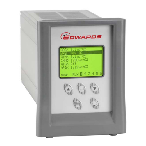
Edwards D397-00-000 User manual

D397-21-880
Issue G
Instruction Manual
Instrument Controller
Description Item Number
TIC Instrument Controller D397-00-000

Declaration of Conformity
We, Edwards
Manor Royal,
Crawley,
West Sussex RH10 9LW, UK
declare under our sole responsibility, as manufacturer and person within the EU authorised to
assemble the technical file, that the product(s)
TIC Instrument Controller D397-00-000
TIC Instrument Controller 6-Gauge D397-01-000
TIC Instrument Controller 6-Gauge Capacitance Manometer D397-02-000
TIC Turbo Controller 100W D397-11-000
TIC Turbo Controller 200W D397-12-000
TIC Turbo & Instrument Controller 100W D397-21-000
TIC Turbo & Instrument Controller 200W D397-22-000
to which this declaration relates is in conformity with the following standard(s) or other
normative document(s)
EN61010-1:2001 Safety Requirements for Electrical Equipment for Measurement,
Control and Laboratory Use – Part 1: General Requirements.
EN61326-1:2006 Electrical Equipment for Measurement Control and Laboratory
(Industrial location, Use – EMC Requirements.
Class B Emissions)
and fulfils all the relevant provisions of
2006/95/EC Low Voltage Directive.
2004/108/EC Electromagnetic Compatibility Directive.
Note: This declaration covers all product serial numbers from the date this Declaration was
signed onwards.
11/06/2010, Eastbourne
Mr L Marini, Technical Manage
r
Date and Place
This product has been manufactured under a quality system registered to ISO9001
P200-03-140 Issue C

© Edwards Limited 2009. All rights reserved. Page i
Edwards and the Edwards logo are trademarks of Edwards Limited.
Contents
D397-21-880 Issue G
Contents
Section Page
1 Introduction .......................................................................................1
1.1 Scope and definitions ................................................................................................... 1
1.2 Product description ...................................................................................................... 1
2 Technical data ....................................................................................3
2.1 Electrical data ............................................................................................................ 3
2.2 Operating and storage data ............................................................................................ 3
2.3 Mechanical data .......................................................................................................... 3
2.4 Connections ............................................................................................................... 3
2.4.1 Active gauge connectors ................................................................................................ 3
2.4.2 Logic interface ...........................................................................................................4
2.4.3 Serial communications .................................................................................................. 5
2.4.4 Analogue outputs ........................................................................................................ 6
3 Installation .........................................................................................9
3.1 Unpack and inspect ...................................................................................................... 9
3.2 Fitting the controller .................................................................................................... 9
3.3 Controller electrical connections ....................................................................................12
3.3.1 Connecting the electrical supply .....................................................................................12
3.3.2 Additional earth bonding ..............................................................................................12
3.3.3 Connecting an active gauge ...........................................................................................13
3.3.4 Connecting the logic interface .......................................................................................13
3.3.5 Connecting the serial interface .......................................................................................14
4 Operation ........................................................................................ 17
4.1 Front panel description ................................................................................................17
4.2 Menu structure ..........................................................................................................18
4.3 Navigating the menu ...................................................................................................19
4.4 The view screen .........................................................................................................19
4.5 Turning gauges and relays on/off ....................................................................................19
4.6 Changing list items .....................................................................................................20
4.7 Changing numerical values ............................................................................................20
4.7.1 Entering negative components e.g. 5.00E-03 ......................................................................21
4.8 Gauge setup .............................................................................................................21
4.8.1 Default setup options (all gauges) ...................................................................................22
4.8.2 Gauge status messages .................................................................................................22
4.8.3 Active Pirani Gauge (APG) .............................................................................................22
4.8.4 Active Linear Pirani Gauge (APGX) ...................................................................................23
4.8.5 Active Thermocouple Gauge (ATC-E) control ......................................................................24
4.8.6 Active Strain Gauge (ASG) control ...................................................................................25
4.8.7 Active Inverted Magnetron (AIM) gauge control ....................................................................26
4.8.8 Active Ion Gauge (AIGX-S) control ...................................................................................27
4.8.9 Wide Range Gauge (WRG) .............................................................................................28
4.9 Alarms ....................................................................................................................30
4.10 The main menu ..........................................................................................................30
4.11 Linking gauges ...........................................................................................................30
4.12 Parameters/units .......................................................................................................31
4.13 Screen options ...........................................................................................................31
4.13.1 Organising gauges on the view screen ...............................................................................32
4.14 Relay setpoint outputs .................................................................................................32
4.15 Service information .....................................................................................................32
4.16 Electrical supply failure ...............................................................................................32
gea/0054/07/09

D397-21-880 Issue G
Page ii © Edwards Limited 2009. All rights reserved.
Edwards and the Edwards logo are trademarks of Edwards Limited.
Contents
5 Maintenance ..................................................................................... 33
5.1 Safety .....................................................................................................................33
5.2 Fault finding .............................................................................................................33
5.3 Cleaning the controller ................................................................................................34
5.4 Software updates .......................................................................................................34
5.5 Factory defaults .........................................................................................................34
6 Storage and disposal ........................................................................... 35
6.1 Storage ...................................................................................................................35
6.2 Disposal ...................................................................................................................35
7 Service, spares and accessories .............................................................. 37
7.1 Service ....................................................................................................................37
7.2 Spares .....................................................................................................................37
7.3 Accessories ...............................................................................................................37
Index .............................................................................................. 39
For return of equipment, complete the HS Forms at the end of this manual.
Illustrations
Figure Page
1 Pin connections for an 8-way FCC/RJ45 ............................................................................. 4
2 Pin connection for a 15-way sub-minature ‘D’ type socket ....................................................... 4
3 Pin connections for a 9-way sub-miniature 'D' type socket ........................................................ 6
4 Pin connection for 4-way analogue output connector ............................................................. 6
5 Bench mounted TIC dimensions (mm) ...............................................................................10
6 Front panel removal ....................................................................................................10
7 Rack mounting of a TIC ................................................................................................11
8 Panel cut out drawing ..................................................................................................11
9 Rear panel connections ................................................................................................12
10 IBM PC RS232 interface - 9-way ......................................................................................14
11 IBM PC RS232 interface - 25-way .....................................................................................14
12 RS485 TIC network ......................................................................................................15
13 Front panel display .....................................................................................................17
14 View screen shortcuts ..................................................................................................18
15 Menu structure ..........................................................................................................18
16 New gauge connected ..................................................................................................19
17 Changing numerical values ............................................................................................20
18 Gauge setup screen .....................................................................................................22
19 Gauge setup screen APGX-M ..........................................................................................24
20 Gauge setup screen ASG ...............................................................................................26
21 Gauge setup screen AIGX ..............................................................................................28
22 Gauge setup screen WRG ..............................................................................................29
23 Controlled item .........................................................................................................30
24 Control setup ............................................................................................................31
25 Gauge order set up .....................................................................................................32

© Edwards Limited 2009. All rights reserved. Page iii
Edwards and the Edwards logo are trademarks of Edwards Limited.
Contents
D397-21-880 Issue G
Tables
Table Page
1 Compatible equipment for the Instrument Controller ............................................................. 1
2 Gauge connector pin-out ............................................................................................... 4
3 Logic interface connector pin-out .................................................................................... 5
4 Serial communications connector pin-out ........................................................................... 6
5 Pin allocation for analogue outputs ................................................................................... 7
6 Component checklist .................................................................................................... 9
7 Front panel symbols and their functions ............................................................................17
8 Default setup options (all gauges) ...................................................................................21
9 Gauge status messages .................................................................................................22
10 Error/diagnostic monitoring APG .....................................................................................23
11 Setup options APGX .....................................................................................................23
12 Error/diagnostic monitoring APGX ...................................................................................24
13 ATC-D and ATC-M gauge tubes ........................................................................................24
14 Error/diagnostic monitoring ATC-E ..................................................................................25
15 Setup options ASG ......................................................................................................25
16 Error diagnostic monitoring ASG ......................................................................................26
17 Error/diagnostic monitoring AIM .....................................................................................27
18 Setup options AIGX .....................................................................................................27
19 Error/diagnostic monitoring AIM .....................................................................................28
20 Setup options WRG .....................................................................................................29
21 Error/diagnostic monitoring WRG ....................................................................................29
22 Fault finding .............................................................................................................33
23 Factory default settings ...............................................................................................34
24 Accessories ...............................................................................................................37

This page has been intentionally left blank.
D397-21-880 Issue G
Page iv © Edwards Limited 2009. All rights reserved.
Edwards and the Edwards logo are trademarks of Edwards Limited.

© Edwards Limited 2009. All rights reserved. Page 1
Edwards and the Edwards logo are trademarks of Edwards Limited.
Introduction
D397-21-880 Issue G
1Introduction
1.1 Scope and definitions
This manual provides Installation, Operation and Maintenance instructions for the Edwards Instrument Controller.
You must use the Controller as specified in this manual.
Read this manual before you install and operate the Edwards Instrument Controller. Important safety information is
highlighted as WARNING and CAUTION instructions; you must obey these instructions. The use of WARNINGS and
CAUTIONS is defined below.
CAUTION
Cautions are given where failure to observe the instruction could result in damage to the equipment, associated
equipment and process.
Throughout this manual, page, figure or table numbers are sequential.
The following IEC warning label appears on the controller:
1.2 Product description
The Instrument Controller is provided with a large clear graphics display, easy-to-use control interface via a touch
sensitive keypad, an RS232/485 interface for control and data monitoring on a remote PC and a logic interface for
interface with associated system hardware.
The compatible instruments that can be used with the Instrument Controller are listed in Table 1.
WARNING
Warnings are given where failure to observe the instruction could result in injury or death to
people.
WARNING
Warning - refer to accompanying documentation.
Edwards offer European customers a recycling service.
WARNING
Improper use of the equipment could cause damage to it or injury to people. The user is
responsible for the safe operation and monitoring of the equipment. Hazardous voltages should not
be connected to this unit except where specified.
Table 1 - Compatible equipment for the Instrument Controller
TIC variant Compatibility
TIC Instrument Controller Up to 3 active gauges including: APG, APGX, ATC, ASG, AIM, WRG and AIGX

D397-21-880 Issue G
Page 2 © Edwards Limited 2009. All rights reserved.
Edwards and the Edwards logo are trademarks of Edwards Limited.
This page has been intentionally left blank.

© Edwards Limited 2009. All rights reserved. Page 3
Edwards and the Edwards logo are trademarks of Edwards Limited.
Technical data
D397-21-880 Issue G
2Technicaldata
2.1 Electrical data
2.2 Operating and storage data
2.3 Mechanical data
2.4 Connections
2.4.1 Active gauge connectors
Connector type CEE/IEC 320
Electrical supply 90 to 264 V a.c. 47 to 63 Hz
Power consumption
TIC Instrument Controller 55 VA maximum (D397-00-000)
Peak inrush current 5 A at 110 V a.c D397-00-000
12 A at 240 V a.c D397-00-000
Fuse The unit is self-protecting and has no user replaceable
fuse. The unit will recover once any overload is removed.
Earth Stud M4
Ambient operating temperature range 0 °C to 40 °C
Ambient storage temperature range -30 °C to 70 °C
Maximum ambient operating humidity Max 90% RH non condensing at 40 °C
Maximum operating altitude 3000 m max
IP rating 20
Weight
TIC Instrument Controller 1.3 kg
Connector type FCC/RJ45, 8-way (refer to Figure 1)
Power supply 24 V d.c.
Maximum power rating 21 W total for the three gauges
Input voltage range -0.5 V to 15 V
Output ID current 33 µA, 0 V to 13 V
Control output active: <0.8 V d.c. (2 mA max)
inactive: open (internal pull-up to 24 V)
Control input low: <2.0 V d.c. (Iout<160 µA)
high: >3.5 V d.c. (internally pulled up to 24 V)

D397-21-880 Issue G
Page 4 © Edwards Limited 2009. All rights reserved.
Edwards and the Edwards logo are trademarks of Edwards Limited.
Technical data
Figure 1 - Pin connections for an 8-way FCC/RJ45
2.4.2 Logic interface
Figure 2 - Pin connection for a 15-way sub-minature ‘D’ type socket
Table 2 - Gauge connector pin-out
Pin Allocation
1 Power supply positive
2Powersupplycommon
3Signalinput
4 Identification
5 Signal common
6Controlline1
7Controlline2
8N/C
Connector type 25-way sub-miniature 'D' type socket (refer to Figure 2)
Power supply 24 V d.c.
Maximum output power 5 W
Control output active: <1.1 V d.c. (Iout <20 mA)
<0.8 V d.c. (Iout <2 mA)
inactive: open (internal pull up to 24 V)
Control input low: <2.0 V d.c. (Iout<160 µA)
high: 3.5 V to 24 V d.c. (internal pull up to 24 V)
Analogue output 0 to 10 V (5 mA max)
50 mV resolution

© Edwards Limited 2009. All rights reserved. Page 5
Edwards and the Edwards logo are trademarks of Edwards Limited.
Technical data
D397-21-880 Issue G
2.4.3 Serial communications
Table 3 - Logic interface connector pin-out
Pin Allocation
1Screen
2 Analogue output signal
3 Setpoint 1 output
4 Do not connect
5 Setpoint 5 output
6 Setpoint 4 output
7Powersupplycommon
8 Do not connect
9 Gauge 1 enable input
10 Power supply common
11 Power supply positive
12 Power supply common
13 Power supply common
14 Analogue output common
15 Setpoint 2 output
16 Setpoint 3 output
17 Do not connect
18 Alarm output
19 Setpoint 6 output
20 Gauge 2 enable input
21 Gauge 3 enable input
22 Do not connect
23 Do not connect
24 Do not connect
25 System interlock input (SYSI)
Connector type 9-way sub-miniature 'D' type socket (refer to Figure 3)
RS232 transmit mark: <- 8 V (Iout max: -8 mA)
space: >+8 V (Iout max: +8 mA)
RS232 receive mark: <+1.0 V (Iin max: -2.0 mA)
space: >+2.0 V (Iin max: +2.0 mA)
maximum input: ±12 V
RS232 protocol 9600 baud, 1 stop bit, 8 data bits, no parity
RS485 Output differential: >1.5 V (Iout max: ±25 mA)
Input differential threshold: >± 0.2 V (Iin max: ±1 mA)
Maximum input: -7.0 V to +12 V
Bus load The TIC applies one unit load to the RS485 bus.

D397-21-880 Issue G
Page 6 © Edwards Limited 2009. All rights reserved.
Edwards and the Edwards logo are trademarks of Edwards Limited.
Technical data
Figure 3 - Pin connections for a 9-way sub-miniature 'D' type socket
2.4.4 Analogue outputs
Figure 4 - Pin connection for 4-way analogue output connector
Table 4 - Serial communications connector pin-out
Pin Allocation
1N/C
2RS232transmit
3RS232receive
4N/C
5RS232common
6N/C
7N/C
8RS485dataA
9RS485dataB
Connector type Phoenix 2.5 mm 4-way
mating half Phoenix FK-MC 0.5/4-ST-2.5
(available from Edwards as 5000 17005)
Short circuit protection All signals
Max load Gauge signals: ±1 mA
Common: ±3 mA
Output voltages
Gauge connected: Gauge signal voltage
(±2% ± 15 mv when in range 0 to +10 V)
Gauge connected 12 V (±1.3 V)
gea/d39701/f4
1234

© Edwards Limited 2009. All rights reserved. Page 7
Edwards and the Edwards logo are trademarks of Edwards Limited.
Technical data
D397-21-880 Issue G
Table 5 - Pin allocation for analogue outputs
Pin Allocation
Gauges 1-3 (Top Ports)
1 Gauge 1 signal
2 Gauge 2 signal
3 Gauge 3 signal
4 Common (0 V)

D397-21-880 Issue G
Page 8 © Edwards Limited 2009. All rights reserved.
Edwards and the Edwards logo are trademarks of Edwards Limited.
This page has been intentionally left blank.

© Edwards Limited 2009. All rights reserved. Page 9
Edwards and the Edwards logo are trademarks of Edwards Limited.
Installation
D397-21-880 Issue G
3 Installation
3.1 Unpack and inspect
Remove all of the packaging material and check the Controller. If the Controller is damaged, follow the Edwards
return of equipment procedures that are laid out in the back of this manual. Do not use the Controller if it is
damaged.
Check that your package contains the items that are listed in Table 6. If any of these items are missing, notify your
supplier in writing within three days. If the Controller is not to be used immediately, store the Controller in suitable
conditions as described in Section 6.1.
3.2 Fitting the controller
CAUTION
Rubber feet must be fitted (Figure 5, item 1) so that there are correct clearances for air circulation. If you do
not, the performance of the Controller may be affected at high operating temperatures.
The Controller can be used on a bench-top or can be fitted in a rack or cabinet. Figure 5 shows the dimensions of the
TIC that are required for bench top use.
Note: If the interlocks are not used the logic interface adaptor must be fitted to the 25-way connector.
Table 6 - Component checklist
Quantity Description Check (9)
1 Controller
1 Quick Guide and Health and Safety Information
1TICCD
2 Rear non-slip feet
1 Logic interface plug
1 Analogue output mating half connectors
WARNING
If access to the IEC connector is restricted an additional isolation device should be provided, which
will be easily accessible by an operator.

D397-21-880 Issue G
Page 10 © Edwards Limited 2009. All rights reserved.
Edwards and the Edwards logo are trademarks of Edwards Limited.
Installation
Figure 5 - Bench mounted TIC dimensions (mm)
If a Controller is fitted in a rack, cabinet or panel, follow the directions given in Figure 6, 7and 8.
CAUTION
Allow 150 mm at the rear for cables. Allow 50 mm top and bottom and 15 mm to the sides for sufficient air
circulation. Do not cover any of the ventilation holes.
CAUTION
This unit is IP20 rated. Please ensure that the unit is not installed where fluids can enter into the controller.
CAUTION
The unit must be supported at the rear.
Figure 6 - Front panel removal
WARNING
Ensure that all electrical wiring is safely secured so that people cannot trip on them.
1. Rubber foot
1. Bench top adaptor
2. Fixing screw and washer

© Edwards Limited 2009. All rights reserved. Page 11
Edwards and the Edwards logo are trademarks of Edwards Limited.
Installation
D397-21-880 Issue G
zRemove the bench top adaptor (Figure 6, item 1) by removing the four screws (Figure 6, item 2).
zSlide the Controller into the 19" rack or panel cut out. The use of 19" rack guide rails (Figure 7, item 2) and
support at the rear of the Controller is recommended as shown in Figure 7. The panel cut out information is
defined in Figure 8.
zFix the Controller in place using the four screws removed previously (Figure 7, item 1).
Figure 7 - Rack mounting of a TIC
Figure 8 - Panel cut out drawing
1. Fixing
screw and
washer
2. 19" rack
guide rails

D397-21-880 Issue G
Page 12 © Edwards Limited 2009. All rights reserved.
Edwards and the Edwards logo are trademarks of Edwards Limited.
Installation
3.3 Controller electrical connections
CAUTION
Do not connect Barocel capacitance manometers to the TIC. Doing so will result in damage to the gauge and will
invalidate the warranty.
Figure 9 - Rear panel connections
3.3.1 Connecting the electrical supply
Ensure that the electrical supply switch is set to 'off' and then connect the Controller to the electrical supply with an
appropriate supply cable.
3.3.2 Additional earth bonding
The electrical supply cable normally provides protective earthing for electrical safety. If this is not the case, or if
additional earth bonding is required, then the earth stud on the rear of the Controller (Figure 9, item 4) should be
connected to your vacuum system earth.
Connect a suitably earthed cable between the two nuts fitted to the earth stud on the rear of the TIC.
Note: Do not remove the bottom nut from the earth stud.
WARNING
High voltages exist in the Controller when it is operating. Ensure that the Controller is earthed and
observe all appropriate safety precautions for the safe installation and handling of electrical
equipment. If you do not, there will be a danger of injury or death to people by electric shock.
1. Gauge inputs
2. Logic interface
3. Serial communications port
4. Earth stud
5. Mains input
6. Mains on/off
7. Analogue outputs

© Edwards Limited 2009. All rights reserved. Page 13
Edwards and the Edwards logo are trademarks of Edwards Limited.
Installation
D397-21-880 Issue G
3.3.3 Connecting an active gauge
CAUTION
Do not connect Barocel capacitance manometers to the TIC. Doing so will result in damage to the gauge and will
invalidate the warranty.
Up to three compatible active gauges can be fitted to the gauge connectors on the rear panel. Connect the gauges
using Edwards active gauge cables to each of the three gauge sockets on the rear of the TIC.
Note: Only one AIGX gauge can be connected to the TIC at a time.
3.3.4 Connecting the logic interface
3.3.4.1 Introduction
Note: In most applications it will be preferable not to earth the logic interface power supply common to prevent
earth loops inadvertently occurring.
CAUTION
Do not connect voltages greater than 24 V to the logic interface.
The logic interface provides a number of signals that can be used for monitoring the status of your vacuum system,
and for controlling certain aspects of its operation. These signals can be broadly divided into two groups, control
inputs and status outputs.
3.3.4.2 Using control inputs
Control inputs provide a means of controlling the operation of the TIC and the associated vacuum system from
external sources.
Gauge 1, 2, 3 Enable Pins 9, 20, 21): The gauge enable inputs can be used to control the operation of the gauges. If
gauge enable is open, the associated gauge cannot be turned on, and will turn off if it is operating. To enable the
gauges, connect the required gauge enable line to 0 V.
Note: Only gauges that can be turned on and off will respond to this input. Refer to the gauge manual for further
details.
SYSI: The System interlock input can be used to interlock the TIC to a system fail or control signal. When 'SYSI' is open,
all gauges will turn off. The TIC will also trip into the fail condition. To clear the system interlock and allow the
gauges to start, connect 'SYSI' to 0 V.
Note: Only gauges that can be turned on and off will respond to this input. Refer to the gauge manual for further
details.
3.3.4.3 Using status outputs
Status outputs provide a means for external systems to react based upon the current state of the TIC.
Relay setpoints: The setpoint outputs can be used to interface to external logic or can be used to drive relays. Each
output can be configured in software to activate at a certain pressure. Refer to Section 4.11 for how to configure
these outputs. Each relay can be manually controlled. Refer to Section 4.5.
WARNING
’SYSI’ is not fail safe and should not be relied upon for safety critical applications.

D397-21-880 Issue G
Page 14 © Edwards Limited 2009. All rights reserved.
Edwards and the Edwards logo are trademarks of Edwards Limited.
Installation
Two types of relay box are available as options from Edwards with either 3 or 6 relay outputs.
The relay box has built in relays that can switch external loads and provides a connector to interface to an external
system. Refer to the relay box instructions for further information on using the setpoint outputs.
To drive a relay without a relay box, connect the coil of a suitable 24 V d.c. relay between 'Setpoint Output' (negative)
and 'Power Supply Positive' (positive).
Alarm: Alarm can be used to interface to external logic or can be used to drive a relay. This output is normally active
and will become inactive in the event of an alarm condition.
To drive a relay, connect the coil of a suitable 24 V d.c. relay between 'Alarm Output' (negative) and 'Power Supply
Positive' (positive).
Note: Total current drawn from 24 V pin on logic connector should be 208 mA maximum.
3.3.5 Connecting the serial interface
The TIC has two serial communications protocols built in, RS232 and RS485. RS232 is the simplest interface and can
be used to allow a host PC to control the TIC. RS485 allows a host PC to control a small network of TICs.
3.3.5.1 Connecting RS232
The TIC is fitted with a 9-way 'D' type socket on the rear panel, refer to Figure 9, item 3. The interface uses two lines
for data transfers and an additional line as a signal common. Hardware handshaking is not implemented.
If connecting to an IBM compatible PC fitted with a 9-way 'D' type socket then a 'straight through' male-female 9-way
extension cable can be used to connect the TIC to the computer as shown in Figure 10. Connection to an IBM PC fitted
with a 25-way serial connector should be made as shown in Figure 11.
Use shielded cable for the interface to reduce interference problems and limit the length of the RS232 link to less
than 10 metres. For longer links, either install line drivers or use RS485.
Figure 10 - IBM PC RS232 interface - 9-way
Figure 11 - IBM PC RS232 interface - 25-way
Other manuals for D397-00-000
1
This manual suits for next models
1
Table of contents
Other Edwards Control System manuals
Popular Control System manuals by other brands
Landi Renzo
Landi Renzo A1 V05 Installation and adjustment manual

Landi Renzo
Landi Renzo A1 V05 Installation and adjustment manual
Niles
Niles SVL-1 Installation & operation guide

CYPRES
CYPRES S6AL211A94 manual
Crestron
Crestron CP4-R quick start
Philips
Philips Allegiant LTC 8500 Series Instructions for use
