Edwards Drystar GV80 User manual

A505-75-880
Issue B Original
Instruction Manual
Drystar® GV80 Acoustic Enclosure
Description Item Number
GV80 Acoustic Enclosure A505-75-000

© Edwards Limited 2007. All rights reserved. Page i
Edwards and the Edwards logo are trademarks of Edwards Limited.
Contents
A505-75-880 Issue B
Contents
Section Page
1 Introduction .......................................................................................1
1.1 Scope and definitions ................................................................................................... 1
1.2 Description ................................................................................................................ 1
2 Technical Data ....................................................................................3
3 Installation .........................................................................................5
3.1 Safety ......................................................................................................................5
3.2 Unpack and inspect ...................................................................................................... 5
3.3 Fit the pump to the base assembly ................................................................................... 6
3.4 Fit the acoustic panel ................................................................................................... 8
4 Maintenance ..................................................................................... 11
5 Storage and disposal ........................................................................... 13
5.1 Storage ...................................................................................................................13
5.2 Disposal ...................................................................................................................13
Appendix A1 Correct use of Swagelok connectors .................................................. 15
A1.1 Fit a Swagelok connector ..............................................................................................15
A1.2 Reconnect a Swagelok connector ....................................................................................15
For return of equipment, complete the HS Forms at the end of this manual.
Illustrations
Figure Page
1 Acoustic Enclosure ....................................................................................................... 2
2 Fit the GV80 pump to the base assembly ............................................................................ 7
3 Connect the cooling-water and nitrogen pipelines ................................................................. 9
A1 Fit a Swagelok fitting ..................................................................................................16
A2 Retighten a Swagelok fitting ..........................................................................................16
Edwarsd JP 07/09

A505-75-880 Issue B
Page ii © Edwards Limited 2007. All rights reserved.
Edwards and the Edwards logo are trademarks of Edwards Limited.
Contents
Tables
Table Page
1 Checklist of components ................................................................................................ 6
Associated publications
Publication title Publication number
Vacuum pump and vacuum system safety P400-40-100
Trademark credits
Swagelok™ is trademark of Crawford Fitting Company.

© Edwards Limited 2008. All rights reserved. Page 1
Edwards and the Edwards logo are trademarks of Edwards Limited.
Introduction
A505-75-880 Issue B
1Introduction
1.1 Scope and definitions
This manual provides installation, operation and maintenance instructionsfor the GV80 Acoustic Enclosure. Youmust
use the Acoustic Enclosure as specified in this manual.
Read this manual before you install the Acoustic Enclosure. Important safety information is highlighted as WARNING
and CAUTION instructions; you must obey these instructions. The use of WARNINGS and CAUTIONS is defined below.
CAUTION
Cautions are given where failure to observe the instruction could result in damage to the equipment, associated
equipment and process
The units used throughout this manual conform to the SI international system of units of measurement.
1.2 Description
When fitted to a GV80 pump, the Acoustic Enclosure reduces the noise level emitted from the pump.
Refer to Figure 1. The Acoustic Enclosure has a front panel (12), a rear panel (5), two side panels (3, 11), a top panel
(2), a base assembly (8), a motor partition (1) and an inlet partition (4). The panels are secured in place by four
manually operated catches (13).
The right-hand side panel (3) has a leadthrough hole to allow you to connect the pump-outlet to your exhaust-
extraction system. The left-hand side panel (11) has a transparent sight-glass, which allows you to see the oil-level
in the pump. The top panel (2) has a leadthrough hole which allows you to connect the pump-inlet to your process
system.
The base assembly (8) has: a cable-gland (7) for the pump electrical supply cable; a services panel (10) with
connectors which allow you to connect your cooling-water supply and return pipelines and your nitrogen supply
pipeline to the pump; castors (6) which allow you to move the pump, and levelling feet (9), which allow you raise
the pump off of the floor so that it is level and does not rest on the castors.
With the exception of the base assembly, all of the panels are made from mild steel and have acoustic foam on the
interior surface(s).
WARNING
Warnings are given where failure to observe the instruction could result in injury or death to
people.

A505-75-880 Issue B
Page 2 © Edwards Limited 2008. All rights reserved.
Edwards and the Edwards logo are trademarks of Edwards Limited.
Introduction
Figure 1 - Acoustic Enclosure
A. Side view (with left-hand side panel removed)
B. Top view (with top panel removed)
C. Sectional view
1. Motor partition
2. Top panel
3. Right-hand side panel
4. Inlet partition
5. Rear panel
6. Castor
7. Cable-gland
8. Base assembly
9. Levelling foot
10.Service panel
11.Left-hand side panel
12.Front panel
13.Catch

© Edwards Limited 2008. All rights reserved. Page 3
Edwards and the Edwards logo are trademarks of Edwards Limited.
Technical Data
A505-75-880 Issue B
2TechnicalData
Dimensions (length x width x height): mm 999 x 446 x 529
Mass 54 kg
Cooling-water inlet connector Suitable for 1/2 inch outside diameter tube
Cooling-water outlet connector Suitable for 1/2 inch outside diameter tube
Nitrogen inlet connector Suitable for 1/4 inch outside diameter tube
Electrical supply cable-gland PG29

A505-75-880 Issue B
Page 4 © Edwards Limited 2008. All rights reserved.
Edwards and the Edwards logo are trademarks of Edwards Limited.
Technical Data

© Edwards Limited 2008. All rights reserved. Page 5
Edwards and the Edwards logo are trademarks of Edwards Limited.
Installation
A505-75-880 Issue B
3 Installation
3.1 Safety
A suitably trained and supervised technician must install the Acoustic Enclosure.
If the GV80 pump has been in operation, switch it off and allow it to cool to a safe temperature before you
start installation.
Isolate the GV80 pump and other components in the process system so that they cannot be operated
accidentally.
Ensure that you connect, disconnect and tighten Swagelok connectors correctly: refer to Appendix A1.
When you refer to procedures in the GV80 instruction manual, ensure that you obey all of the appropriate
WARNINGs and CAUTIONs in the manual.
3.2 Unpack and inspect
Remove all packing materials and protective covers and check the Acoustic Enclosure. If any item is damaged, notify
your supplier and the carrier in writing within three days. State the Item Number of the Acoustic Enclosure, together
with your order number and your supplier’s invoice number. Do not use the Acoustic Enclosure if it is damaged.
Check that you have received the items listed in Table 1 (see page 4). If any item is missing, notify your supplier in
writing within three days.
If the Acoustic Enclosure is not to be used immediately, replace any packing and protective covers and store in
suitable conditions, as described in Section 5.1.
WARNING
Obey the safety instructions given below and take note of appropriate precautions. If you do not,
you can cause injury to people and damage to equipment.

A505-75-880 Issue B
Page 6 © Edwards Limited 2008. All rights reserved.
Edwards and the Edwards logo are trademarks of Edwards Limited.
Installation
3.3 Fit the pump to the base assembly
We recommend that you fit the Acoustic Enclosure when you install your GV80 pump. Use the following procedure
and (where necessary) the instruction manual supplied with the GV80 pump:
1. Fill the pump with oil: refer to the GV80 manual.
2. Refer to Figure 2 detail A. Move the base assembly (5) close to where you will install the GV80 pump, then lower
the levelling feet (6) so that the base assembly is level, is supported by the levelling feet (not the castors).
3. Refer to detail B. Undo and remove the M8 bolt and washers (8) from each of the four vibration isolators (9) on
the base assembly.
4. Use suitable lifting equipment to lift the GV80 pump over the base assembly (5), with the pump-motor at the
same end of the assembly as the cable-gland (4): refer to the GV80 manual.
5. Lower the pump onto the base assembly (5), so that the fixing holes in the pump frame (1) align with the fixing
holes on the top of the vibration isolators (9), then use the bolts and washers removed in Step 3 to secure the
pump frame (1) to the vibration isolators.
6. Refer to detail C. Use the M6 nuts (12), plain washers (13) and shake-proof washers (11) to connect the earth
(ground) cable (3, connected to the base assembly) to the earth (ground) stud (2) on the GV80 pump frame (1).
7. Remove the lifting bolts from the pump.
8. Refer to Figure 3, detail C. Use two of the 1/2 inch tube inserts (6) to fit one of the lengths of 1/2 inch outside
diameter vinyl tube (7) between the GV pump outlet elbow (5) and the cooling-water outlet connector (8) on the
base assembly.
9. Use the other two 1/2 inch tube inserts (6) to fit the other length of 1/2 inch outside diameter vinyl tube (7)
between the GV pump inlet banjo fitting (14) and the cooling-water inlet connector (9) on the base assembly.
Table 1 - Checklist of components
Qty Description Check ()
1 Right-hand side panel
1 Left-hand side panel
1 Front panel
1Rearpanel
1Toppanel
1 Outlet partition
1Fancover
1 Base assembly
Fitting kit, which contains:
2 1.2 m length of vinyl tube: 1/2 inch outside
1 1.2 m length of vinyl tube: 1/2 inch outside
6 1/2 inch tube inserts
3 1/4 inc tube inserts
2 M6 nuts
2 M6 plain washers
2 M6 shake-proof washers
1M6springwasher

© Edwards Limited 2008. All rights reserved. Page 7
Edwards and the Edwards logo are trademarks of Edwards Limited.
Installation
A505-75-880 Issue B
Figure 2 - Fit the GV80 pump to the base assembly
1. GV80 pump frame
2. Earth (ground) stud
3. Earth (ground) wire
4. Cable-gland
5. Base assembly
6. Levelling foot
7. Castor
8. M8 bolt and washer
9. Vibration isolator
10.Earth (ground) stud
11.Shake-proof washer
12.Nut
13.Plain washer

A505-75-880 Issue B
Page 8 © Edwards Limited 2008. All rights reserved.
Edwards and the Edwards logo are trademarks of Edwards Limited.
Installation
10.Use the two 1/4 inch tube inserts (11) to fit the length of 1/4 inch outside diameter vinyl tube (12) between the
GV pump nitrogen inlet fitting (13) and the nitrogen inlet connector (10) on the base assembly.
11.Refer to Figure 2. Ensure that the levelling feet (6) are fully raised, then push the pump and base assembly on its
castors (7) into its final operating location.
12.Lower and adjust the levelling feet (6), so that the pump is level and so that it does not rest on the castors.
13.Pass the pump electrical supply cable through the cable-gland (4) and route the cable to the pump-motor.
14.Connect the electrical supply cable to the pump-motor (refer to the GV80 manual), then tighten the cable-gland
(4) to secure the cable.
3.4 Fit the acoustic panel
1. Refer to Figure 1. Slide the motor partition (1) into the rear panel (5), then fit the assembly to the base
assembly so that the motor partition goes over the pump-motor, and so that the locating holes in the bottom of
the motor partition and rear panel go over the locating pins on the base assembly (8).
2. Fit the front panel (12) to the base assembly; ensure that the locating holes in the base of the panel fit over the
locating pins on the base assembly (8).
3. Fit the inlet partition (4) onto the base assembly (8).
4. Fit the top panel (2); ensure that the locating holes under the top panel fit over the locating pins on the tops of
the front and rear panels (12, 5).
5. Fit the right-hand side panel (3) to the base assembly (8): slide the locating holes on the base of the panel over
the locating pins on the base assembly, then swing the top of the panel into place. Ensure that the pump-outlet
does not damage the acoustic foam when you fit the panel. Use the two catches (13) to secure the side panel to
the top panel.
6. Fit the left-hand side panel (11) to the base assembly (8): slide the locating holes on the base of the panel over
the locating pins on the base assembly, then swing the top of the panel into place. Use the two catches (13) to
secure the side panel to the top panel.
7. Refer to Figure 3. Connect your cooling-water supply pipeline to the cooling-water inlet (3) on the services panel
(1).
8. Connect your cooling-water return pipeline to the cooling-water outlet (2) on the services panel (1).
9. Connect your nitrogen supply pipeline to the nitrogen inlet (4) on the services panel.

© Edwards Limited 2008. All rights reserved. Page 9
Edwards and the Edwards logo are trademarks of Edwards Limited.
Installation
A505-75-880 Issue B
Figure 3 - Connect the cooling-water and nitrogen pipelines
1. Services panel
2. Cooling-water outlet
3. Cooling-water inlet
4. Nitrogen inlet
5. Pump outlet elbow
6. 1/2 inch tube insert
7. 1/2 inch vinyl tube
8. Cooling-water outlet fitting
9. Cooling-water inlet fitting
10.Nitrogen inlet fitting
11.1/4 inch tube insert
12.1/4 inch vinyl tube
13.Pump nitrogen inlet
14.Pump water inlet banjo fitting

A505-75-880 Issue B
Page 10 © Edwards Limited 2008. All rights reserved.
Edwards and the Edwards logo are trademarks of Edwards Limited.
Installation

© Edwards Limited 2008. All rights reserved. Page 11
Edwards and the Edwards logo are trademarks of Edwards Limited.
Maintenance
A505-75-880 Issue B
4Maintenance
Do the following checks when you maintain your GV80 pump:
Check that the pump is level and is supported on the levelling feet, and that the lock-nuts on the levelling
feet are tight.
Check that the catches on the panels are secure.

A505-75-880 Issue B
Page 12 © Edwards Limited 2008. All rights reserved.
Edwards and the Edwards logo are trademarks of Edwards Limited.
Maintenance

© Edwards Limited 2008. All rights reserved. Page 13
Edwards and the Edwards logo are trademarks of Edwards Limited.
Storage and disposal
A505-75-880 Issue B
5 Storage and disposal
5.1 Storage
Refit any packing materials and protective covers and store the Acoustic Enclosure in cool, dry conditions.
When required for use, install the Acoustic Enclosure as described in Section 3.
5.2 Disposal
Dispose of the Acoustic Enclosure and any components safely in accordance with all local and national safety and
environmental requirements.

A505-75-880 Issue B
Page 14 © Edwards Limited 2008. All rights reserved.
Edwards and the Edwards logo are trademarks of Edwards Limited.
Storage and disposal

© Edwards Limited 2008. All rights reserved. Page 15
Edwards and the Edwards logo are trademarks of Edwards Limited.
Appendix A1
A505-75-880 Issue B
Appendix A1 Correct use of Swagelok
connectors
Note: We recommend that you use a second spanner to hold the connector in position when you connect or
disconnect a Swagelok connector.
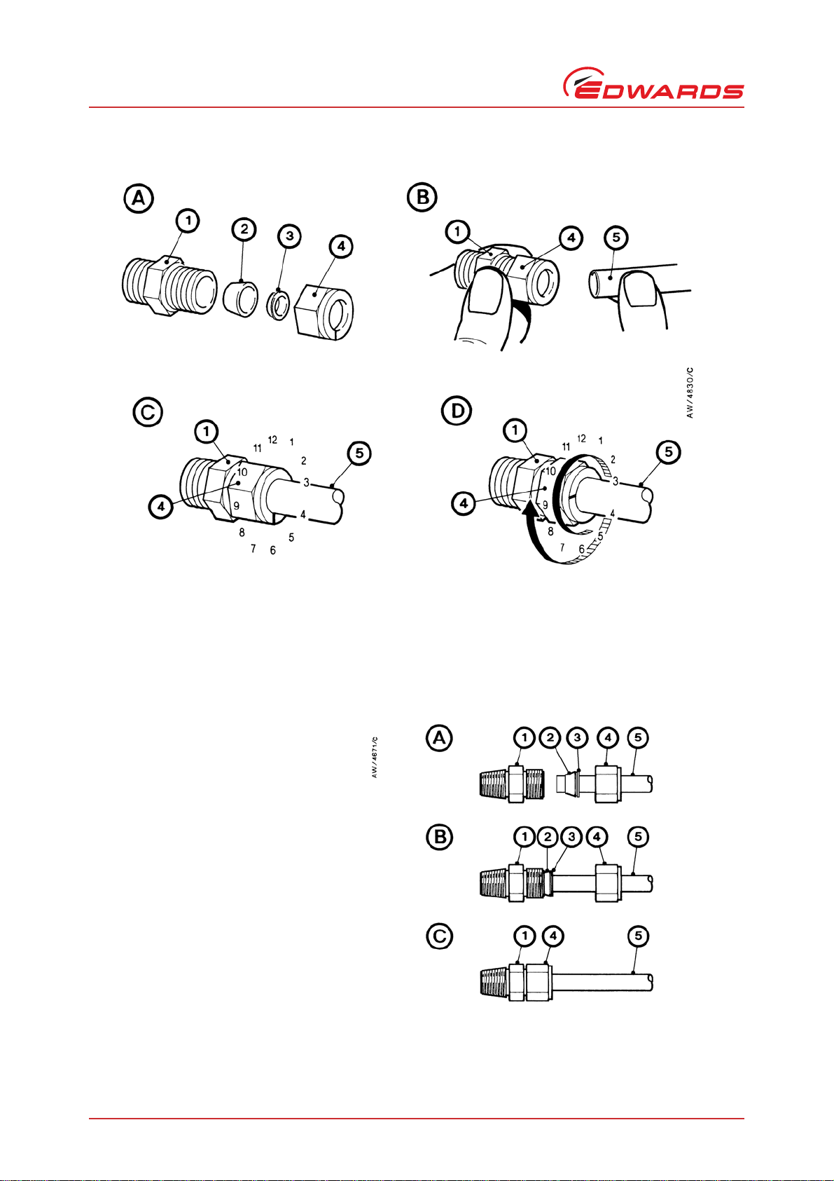
A1.1 Fit a Swagelok connector
1. Refer to Figure A1-1 detail A. Undo and remove the nut (4) from the Swagelok connector (1). Ensure that the
front (tapered) ferrule (2) and the rear ferrule (3) are correctly orientated as shown in detail A, then loosely
refit the nut (4) to the connector (1).
2. Refer to detail B. Insert the tube (5) through the nut (4) and into the Swagelok connector (1). Ensure that the
tube rests firmly on the shoulder inside the fitting, and that the nut (4) is finger tight.
3. Tighten the nut (4) until you cannot rotate the tube (5). If you cannot turn the tube because of how it is
installed, tighten the nut by 1/8th of a turn.
4. Refer to detail C. Mark the nut (4) at the six o’clock position.
5. Refer to detail D. Hold the body of the connector steady, then turn the nut (4) by 11/4 turns (to the nine o’clock
position) to fully tighten the connection.
A1.2 Reconnect a Swagelok connector
You can disconnect and reconnect a Swagelok connector many times and still obtain a correct leak-proof seal. Refer
to Figure A1-2 detail A which shows a Swagelok connector after you have disconnected it.Use the following procedure
to reconnect it:
1. Refer to detail B. Insert the tube (5) with the swaged ferrules (2, 3) into the Swagelok fitting (1), until the front
ferrule (2) is fully in the body of the fitting.
2. Refer to detail C. Tighten the nut (4) by hand.
3. Use a wrench or spanner to turn the nut (4) to its original position (you will feel an increase in resistance when
the nut is in its original position), then tighten the nut slightly.
A505-75-880 Issue B
Page 16 © Edwards Limited 2008. All rights reserved.
Edwards and the Edwards logo are trademarks of Edwards Limited.
Appendix A1
Figure A1 - Fit a Swagelok fitting
Figure A2 - Retighten a Swagelok fitting
1. Swagelok connector
2. Front (tapered) ferrule
3. Rear ferrule
4. Nut
5. Tube
1. Swagelok connector
2. Front (tapered) ferrule
3. Rear ferrule
4. Nut
5. Tube
Table of contents
Other Edwards Enclosure manuals


Popular Enclosure manuals by other brands

HP
HP Cray Cls 4U 106-18TB Disassembly instructions

HighPoint
HighPoint RocketStor 6314A user manual

Heckler Design
Heckler Design WindFall H480 Assembly & installation

StarTech.com
StarTech.com S3520WU33ER Spec sheet

Altec Lansing
Altec Lansing 5194XM CEILING SPEAKER ACCESSORY manual

Rittal
Rittal VX25-SV Assembly instructions


