Edwards A506-36-880 User manual

A506-36-880
Issue A Original
Instruction Manual
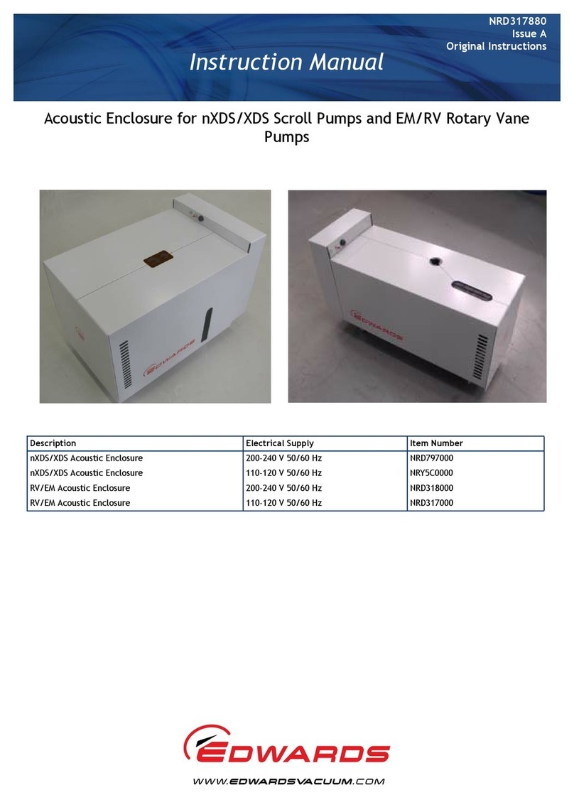
Acoustic Enclosure for XDS Scroll Pumps and Rotary Vane Pumps
Description Electrical Supply Item Number
XDS Acoustic Enclosure 200-240 V 50/60 Hz A506-36-903
XDS Acoustic Enclosure 110-120 V 50/60 Hz A506-36-906
RV/EM Acoustic Enclosure 200-240 V 50/60 Hz A506-35-903
RV/EM Acoustic Enclosure 110-120 V 50/60 Hz A506-35-906

Declaration of Conformity
We, Edwards Limited,
Crawley Business Quarter,
Manor Royal,
Crawley,
West Sussex, RH10 9LW, UK
declare under our sole responsibility, as manufacturer and person within the EU authorised
to assemble the technical file, that the product(s)
EM/RV Enclosure High volts A506-35-903
EM/RV Enclosure Low volts A506-35-906
XDS Enclosure High volts A506-36-903
XDS Enclosure Low volts A506-36-906
to which this declaration relates is in conformity with the following standard(s) or other
normative document(s)
EN61010-1:2010 Safety Requirements for Electrical Equipment for Measurement,
Control and Laboratory Use. General Requirements
EN12100:2010 Safety of machinery. General principles for design. Risk
assessment and risk reduction.
EN50581:2012 Technical Documentation for the Assessment of Electrical and
Electronic Products with respect to the Restriction of Hazardous
Substances
and fulfils all the relevant provisions of
2014/35/EU Low Voltage Directive
2012/19/EU Waste from Electrical and Electronic Equipment (WEEE) Directive
2011/65/EU Restriction of Certain Hazardous Substances (RoHS) Directive
Note: This declaration covers all product serial numbers from the date this Declaration was
signed onwards.
10.08.2015, Burgess Hill
P200-07-100 Issue C
Mr Peter Meares
Senior Technical Support Manager, General Vacuum Date and Place
This product has been manufactured under a quality
management
system
certified to ISO
9001:2008

© Edwards Limited 2012. All rights reserved. Page i
Edwards and the Edwards logo are trademarks of Edwards Limited.
Contents
A506-36-880 Issue A
Contents
Section Page
1 Introduction .......................................................................................1
1.1 Scope and definitions ................................................................................................... 1
2 Technical data ....................................................................................2
2.1 Specifications ............................................................................................................. 2
3 Installation .........................................................................................3
3.1 Safety ......................................................................................................................3
3.2 Installing the XDS Acoustic Enclosure ................................................................................. 4
3.3 Installing RV EM Acoustic Enclosure ................................................................................... 5
4 Operation ..........................................................................................8
4.1 Safety ......................................................................................................................8
4.2 Over temperature alarm ................................................................................................ 8
4.3 Buzzer test ................................................................................................................ 8
4.4 Pump Monitoring ......................................................................................................... 8
5 Maintenance .......................................................................................9
5.1 General .................................................................................................................... 9
5.2 Servicing ..................................................................................................................10
5.3 Cleaning ..................................................................................................................10
6 Disposal .......................................................................................... 11
For return of equipment, complete the HS Forms at the end of this manual.
Illustrations
Figure Page
1 Specifications of XDS and RV/EM pumps ............................................................................. 2
2 Inserting XDS pump into Acoustic Enclosure ......................................................................... 4
3 Locating left hand panel on side of pump ........................................................................... 4
4 Fitting second cover to right hand side of pump ................................................................... 4
5 Attaching inlet and exhaust fittings .................................................................................. 5
6 Locating first panel on left hand side of pump ..................................................................... 6
7 Fitting second cover to right hand side of pump ................................................................... 6
8 Fitting end cover ......................................................................................................... 6
9 Removing front panel to view sight glass ............................................................................ 9
10 Removing panel to gain access to filler cap ......................................................................... 9
gea/0137/01/11

A506-36-880 Issue A
Page ii © Edwards Limited 2012. All rights reserved.
Edwards and the Edwards logo are trademarks of Edwards Limited.
Contents
Tables
Table Page
1 Pump noise levels ........................................................................................................ 2
Associated publications
Publication title Publication number
Vacuum pump and vacuum system safety P400-40-100

© Edwards Limited 2012. All rights reserved. Page 1
Edwards and the Edwards logo are trademarks of Edwards Limited.
Introduction
A506-36-880 Issue A
1Introduction
1.1 Scope and definitions
The Acoustic Enclosure is designed to be used in an industrial or laboratory environment. All Edwards XDS and nXDS
scroll pumps will fit the XDS Acoustic Enclosure and all RV and EM pumps up to E2M28 will fit the RV/EM Acoustic
Enclosure.
The enclosure is designed to slot together without removable fixings and so requires no tooling to assemble or
dismantle it. It is powered by a power cable fitting into an IEC 320 socket.
Note: The power cable for the pump is connected to its own supply. This supply should have an external means of
isolation and not rely upon the on/off switch located on the pump.
Read this manual before you install and operate the Acoustic Enclosure. Important safety information is highlighted
as WARNING and CAUTION instructions; you must obey these instructions. The use of WARNINGS and CAUTIONS is
defined below.
CAUTION
Cautions are given where failure to observe the instruction could result in damage to the equipment, associated
equipment and process.
The following IEC warning labels appear on the Acoustic Enclosure:
WARNING
Warnings are given where failure to observe the instruction could result in injury or death to
people.
Warning - refer to accompanying documentation.
Warning - risk of electric shock.

A506-36-880 Issue A
Page 2 © Edwards Limited 2012. All rights reserved.
Edwards and the Edwards logo are trademarks of Edwards Limited.
Technical data
2Technicaldata
2.1 Specifications
Figure 1 - Specifications of XDS and RV/EM pumps
The fuse rating is 5 amps, Type T, 20mm long x 5mm diameter (RS668-6010 or equivalent).
The Acoustic Enclosure can be used to attenuate the noise from the XDS, nXDS range of scroll pumps, EM and RV
pumps typically by the figures listed in Table 1.
Two fans are fitted. Fan 1 starts up when the power is on. Fan 2 is controlled by a thermal switch set to operate when
the internal temperature exceeds 35 ± 5°C.
Environmental conditions:
XDS RV/EM
Dimensions: Length 778 mm
Width 442 mm
Height 580 mm
Dimensions: Length 790 mm
Width 285 mm
Height 460 mm
Mass: 37 kg Mass: 23 kg
Table 1 - Pump noise levels
XDS5 8 dBA
XDS10 8 dBA
XDS35i 9 dBA
nXDS 5 dBA
RV 7dBA
E2M28 7 dBA
Altitude 2000 m
Ambient temperature 30°C

© Edwards Limited 2012. All rights reserved. Page 3
Edwards and the Edwards logo are trademarks of Edwards Limited.
Installation
A506-36-880 Issue A
3 Installation
3.1 Safety
A suitably trained and supervised technician must install the Acoustic Enclosure.
Ensure that all equipment is safe and in a suitable condition to be installed in the enclosure.
For safety issues, refer to Edwards Vacuum Pump and Vacuum System Safety Publication P400-40-100 or
contact Edwards if in doubt.
Casters should be locked when the pump is in operation.
Route all electrical cables in a safe manner.
WARNING
Obey the safety instructions given below and take note of appropriate precautions. If you do not,
you can cause injury to people and damage to equipment.
WARNING
Care should be taken when removing the enclosure from the packaging and also when removing
the enclosure side panels.
WARNING
Use suitable lifting equipment or at least two people to lift the empty Acoustic Enclosure.
WARNING
Do not lift the Acoustic Enclosure with a pump installed.
WARNING
Be careful not to drop any of the enclosure panels during assembly/disassembly as this may either
damage the panel or cause injury.
WARNING
Do not install the enclosure on a slope. When the castors are unlocked the enclosure could move
and cause injury.

A506-36-880 Issue A
Page 4 © Edwards Limited 2012. All rights reserved.
Edwards and the Edwards logo are trademarks of Edwards Limited.
Installation
3.2 Installing the XDS Acoustic Enclosure
The various elements of the Enclosure are designed to slot together without additional fixings.
Figure 2 - Inserting XDS pump into Acoustic Enclosure
Figure 3 - Locating left hand panel on side of pump
Figure 4 - Fitting second cover to right hand side of pump

© Edwards Limited 2012. All rights reserved. Page 5
Edwards and the Edwards logo are trademarks of Edwards Limited.
Installation
A506-36-880 Issue A
After removing all packaging:
Remove side panels by lifting (this will disengage the panel from the locating pins) and moving to the side. Be
careful not to drop a panel.
Insert XDS pump - refer to Figure 2.
Attach inlet and exhaust fittings. Note that sufficient length will be needed to clear enclosure.
Locate first panel on left hand side of pump - refer to Figure 3.
Adjust pump position to suit.
Position pump power cable through hole provided.
Switch the Pump start switch to ON.
Fit Second Cover to right hand side of pump - refer to Figure 4.
3.3 Installing RV EM Acoustic Enclosure
The various elements of the Enclosure are designed to slot together without additional fixings.
Figure 5 - Attaching inlet and exhaust fittings

A506-36-880 Issue A
Page 6 © Edwards Limited 2012. All rights reserved.
Edwards and the Edwards logo are trademarks of Edwards Limited.
Installation
Figure 6 - Locating first panel on left hand side of pump
Figure 7 - Fitting second cover to right hand side of pump
Figure 8 - Fitting end cover

© Edwards Limited 2012. All rights reserved. Page 7
Edwards and the Edwards logo are trademarks of Edwards Limited.
Installation
A506-36-880 Issue A
After removing all packaging:
Attach inlet and exhaust fittings. Note that an extension piece will be needed if Exhaust Mist Filter (EMF) or
an inlet accessory is to be fitted - refer to Figure 5.
Locate first panel on left hand side of pump - refer to Figure 6.
Adjust pump position to suit.
Position pump power cable through hole provided.
Switch the motor start switch to ON.
Fit Second Cover on right hand side of pump - refer to Figure 7.
Fit end cover - refer to Figure 8.

A506-36-880 Issue A
Page 8 © Edwards Limited 2012. All rights reserved.
Edwards and the Edwards logo are trademarks of Edwards Limited.
Operation
4 Operation
4.1 Safety
Plug the power cable into the IEC 320 socket at back of the enclosure.
Switch on the power.
Fan 1 should start up on the power being switch on.
Check there is airflow from the fan by placing your hand over the mesh at the opposite end of the box from
the fan.
Do not block the inlet of the fan or the ventilation mesh. Allow at least 50mm clearance around the Acoustic
Enclosure.
If the internal temperature reaches 35 ± 5 °C the second fan will switch in.
4.2 Over temperature alarm
There is a warning buzzer on the front face of the bulkhead. This is triggered by a thermal switch inside the Enclosure,
which is set to 50 ± 5 °C. The buzzer will be triggered if the fan fails and the pump continues running, interruption
of the power supply or similar event. If the pump overheats it will thermally protect itself.
The buzzer will run for at least 12 hours on battery back up.
4.3 Buzzer test
There is a push button test switch for checking that the battery backed up buzzer works. This can be tested either
with the unit connected to the Mains supply or on battery back up.
4.4 Pump Monitoring
It is recommended that the user should use appropriate techniques to monitor the pump temperature and initiate
protective measures in fault-intolerant applications.
WARNING
This enclosure must only be operated in an upright position. Isolate power before removing the
pump from the enclosure.

© Edwards Limited 2012. All rights reserved. Page 9
Edwards and the Edwards logo are trademarks of Edwards Limited.
Maintenance
A506-36-880 Issue A
5Maintenance
5.1 General
Note: The unit is easily movable on its castors.
The enclosure requires no regular maintenance if the indicated temperature is within the guidelines.
For the RV EM pumps regular checks can be carried out.
Figure 9 - Removing front panel to view sight glass
Figure 10 - Removing panel to gain access to filler cap
To check the oil level, remove the front end panel (lift and pull towards you). The sight glass is visible
through the opening in the covers - refer to Figure 9.
If the oil level needs to be topped up, remove panel to gain access to the filler cap - refer to Figure 10.
CAUTION
With the pump enclosed by the Acoustic Enclosure, regular checks of the pump oil level should be made.

A506-36-880 Issue A
Page 10 © Edwards Limited 2012. All rights reserved.
Edwards and the Edwards logo are trademarks of Edwards Limited.
Maintenance
The frequency of checks will depend on the particular application, but note that oil consumption will increase under
the following circumstances:
Running at elevated inlet pressures (either as a result of the application or a vacuum leak.)
Running with gas ballast.
Mist filter in conjunction with an oil return kit not fitted.
5.2 Servicing
The enclosure requires no regular servicing but it is suggested that the Acoustic enclosure is inspected yearly to
ensure safe operation.
If the fan stops turning, check the electrical cable is still connected and that the fuse does not need replacing. If the
fan needs replacing a suitably trained and supervised technician must complete the task.
Ensure that the air duct is checked regularly and clean where appropriate.
Replace battery (PP9 Alkaline-Manganese dioxide cell) annually, or in case of failure (can be tested by sounding
buzzer).
Edwards spare part recommended:
There is no other servicing required.
5.3 Cleaning
The outside surface can be cleaned with a damp cloth and mild detergent. Do not allow water near the electrical
components.
Fan unit A726-01-804

© Edwards Limited 2012. All rights reserved. Page 11
Edwards and the Edwards logo are trademarks of Edwards Limited.
Disposal
A506-36-880 Issue A
6Disposal
Dispose of any used equipment safely in accordance with all local and national safety and environmental
requirements.
Ensure the battery is disposed of safely in accordance with all local and national safety and environmental
requirements.

A506-36-880 Issue A
Page 12 © Edwards Limited 2012. All rights reserved.
Edwards and the Edwards logo are trademarks of Edwards Limited.
This page has been intentionally left blank.

This page has been intentionally left blank.

This page has been intentionally left blank.

Return the equipment or components for service
Before you send your equipment to us for service or for any other reason, you must send us a
completed Declaration of Contamination of Vacuum Equipment and Components – Form HS2. The
HS2 form tells us if any substances found in the equipment are hazardous, which is important for
the safety of our employees and all other people involved in the service of your equipment. The
hazard information also lets us select the correct procedures to service your equipment.
We provide instructions for completing the form in the Declaration of Contamination of Vacuum
equipment and Components – Procedure HS1.
If you are returning a vacuum pump, note the following:
If a pump is configured to suit the application, make a record of the configuration before
returning the pump. All replacement pumps will be supplied with default factory settings.
Do not return a pump with accessories fitted. Remove all accessories and retain them for
future use.
The instruction in the returns procedure to drain all fluids does not apply to the lubricant in
pump oil reservoirs.
Download the latest documents from www.edwardsvacuum.com/HSForms/, follow the procedure in
HS1, fill in the electronic HS2 form, print it, sign it, and return the signed copy to Edwards.
Note: If we do not receive a completed HS2 form, we will not accept the return of the
equipment.
P80081000, Issue A

P800‐80‐000IssueT
edwardsvacuum.com
This manual suits for next models
4
Table of contents
Other Edwards Enclosure manuals
Popular Enclosure manuals by other brands
Gallien-Krueger
Gallien-Krueger Neo series owner's manual
Kingston Technology
Kingston Technology StorCase Technology Rhino JR RJR110 user guide

BE QUIET!
BE QUIET! DARK BASE PRO 901 user manual
Apevia
Apevia Beast 680W user guide
Formcase
Formcase T36 instruction manual
GME
GME SS002B Installation and user guide
