Edwards 2400 Series Manual

Technical Bulletin # 970510 Page 1of 7
Edwards Signaling Products
90 Fieldstone Court
Cheshire, CT 06410
(203)699-3000
FAX (203)699-3108
Technical Bulletin # 970510
Date: August 29,1997
Product: 2400 Series
Product Category: Fire Alarm
Subject: 2400 Series Fire Alarm Panel Detailed Programming Instructions
Before Proceeding: Ensure that all Expansion Modules have been installed and
their ribbon cables connected.
POWER
ZONE
DISABLED
ALARM
SILENCED
ALARMGROUND
FAULT
SYSTEM
TROUBLE
CIRCUIT1
CIRCUIT2
SIGNAL
TROUBLE
TROUBLE
SILENCEENABLE
DISABLE
ENABLE
DISABLE
ALARM
SILENCE
RESET
AUX
GNDNL
ALARMTROUBLESIG1SIG2INP1INP2
PGM
MODE
+ + ++ +
2
4
V
D
C
@500mA24VDC
1A,MAX.24VDC
1A,MAX.
2
4
V
D
C
2.5A,MAX.
2
4
V
D
C
2.5A,MAX.
Reset Button Alarm Silence Button
Zone Trouble LED
Signal Circuit Trouble
LED
Zone Trouble LED
Programming Mode
Slide Switch
System Trouble LEDPower LED
Trouble Silence
Button
Zone Disabled
LED
Alarm Silenced
LED
Alarm LED

Technical Bulletin # 970510 Page 2of 7
Step 1: Module Placement & Verification
A. Move the Programming Slide Switch to the ‘on’ position (up). The System
Trouble LED will begin to flash and the Trouble Buzzer will sound at 20
ppm (pulses per minute).
B. Press the Reset Button. All the panel LEDs will turn on and then turn off.
After about 15 seconds the green power LED will begin a single phase
flash (flash and pause, flash and pause, etc.) the System Trouble LED
will turn a steady amber and the Zone Trouble LED’s will turn to a steady
amber.
C. At this point all Zone Trouble LED’s should be a steady amber, as well as
any Expansion Modules Enable/Disable LED.
Step 2: Initiating Device Circuit Programming
A. Press the Reset Button. The green power LED will begin a two phase flash
(flash-flash-pause, flash-flash-pause, etc.), the Zone 1 Trouble LED will
turn to steady red and the Circuit 1 and Circuit 2 Signal Trouble LED’s will
turn a steady amber.note 1
B. Use the Trouble Silence Button to step through the different zone types.
The different zone types as well as their Zone Trouble LED Color Codes
are listed in the following chart.
Initiating Device Circuit Zone Type Zone Enable/Disable LED Color Code
Alarm, NonVerified Detector Steady Red LED
Alarm, Verified Detector & Dry Contact
Alarm Initiating Devices (Do NOT use
this option. High Impedance Detectors
are not available)
Single Phase Flash Red (flash-pause,
flash-pause, etc.)
Alarm , Verified Detector ONLY For Low
Impedance devices only. Two Phase Flash Red (flash-flash-
pause, flash-flash-pause, etc.)
Normally-Open Supervisory Steady Amber
Waterflow Steady Green
Waterflow with Retard Single Phase Flash Green (flash-
pause, flash-pause, etc.)
note 1 The Zone Trouble LED will be steady red unless it was previously programmed as a
different zone type.

Technical Bulletin # 970510 Page 3of 7
Definitions:
Alarm Verification - After receipt of an alarm by a smoke detector, verified
Zones attempt to automatically reset the detector. Receipt of a second alarm
within the 60-second confirmation period after the automatic detector reset
period transmits the alarm to the panel.
Waterflow Zone - Initiating Device Circuits defined, as waterflow zones do not
permit alarm silence while the alarm is active.
Waterflow Zone with Retard - Initiating Device Circuits defined as waterflow
with retard do not permit alarm silence while the alarm is active and also delay
the waterflow signals to the panel to prevent false alarms due to fluctuations in
water pressure.
Alarm Non-Verification - As soon as a device on this type of zone goes into
alarm, an alarm is transmitted to the panel.
Supervisory Operation - An Initiating Device Circuit used to monitor the
status of critical fire protection equipment (e.g., Tamper switches for a sprinkler
system).
C. Once an Initiating Device Circuit Zone Type is selected, the Indicating
Appliance Circuits (IAC’s) operated by this zone must be chosen. This is
indicated by the Circuit 1 and Circuit 2 Signal Trouble LED’s. If both LEDs
are steady amber, then both SIG 1 (Circuit 1) and SIG 2 (Circuit 2) are
operated by that zone (This is the Factory Default.). If only Circuit 1’s
Signal Trouble LED is on then only SIG 1 (Circuit 1) is operated by this
zone. If only Circuit 2’s Signal Trouble LED is on then only SIG 2 (Circuit
2) is operated by this zone. Press the Alarm Silence Button to change the
Indicating Appliance Circuit operated by this zone.
D. To program the next Initiating Device Circuit, press the Reset Button and
repeat steps B and C above.
E. After the last Initiating Device Circuit has been programmed press the
Reset Button.
Step 3: Indicating Appliance Circuits Programming
A. The green power LED should be performing a three-phase flash (flash-
flash-flash-pause, flash-flash-flash-pause, etc.). The System Trouble LED
should be steady amber, the Alarm Silenced LED should be performing a

Technical Bulletin # 970510 Page 4of 7
single phase flash (flash-pause, flash-pause, etc.) and the Circuit 1 Signal
Trouble LED should be on steady amber. note 2
B. Press the Alarm Silence Button to chose the Indicating Appliance Circuit 1
(SIG 1) as Silenceable or Non-Silenceable.
Indicating Appliance Circuit Mode Alarm Silenced LED Code
Silenceable Single Phase Flash Amber (flash-
pause, flash-pause, etc.)
Non-Silenceable OFF
C. Press the Trouble Silence Button to chose the desired Indicating Appliance
Circuit output signal rate. The Indicating Appliance Circuit Output Rate and
their Signal Circuit Trouble LED codes are listed in the following chart.
Indicating Appliance Circuit Output Rate Signal Circuit Trouble LED Code
Continuous Steady
120 Pulses per minute 120 Flashes per Minute
Temporal (3-3-3) Flash-Flash-Flash-Pause and repeat
Continuous California Rate 10 seconds ON, 5 Seconds OFF…
March Time California Rate 10 Seconds ON @ 120 PPM, 5
Seconds OFF…
D. After Circuit 1 is programmed press the Reset Button. The Alarm Silenced
LED should be performing a single phase flash (flash-pause, flash-pause,
etc.) and the Circuit 2 Signal Trouble LED should be on steady amber.note3
E. Repeat steps B and C.
F. After Indicating Appliance Circuit 2 has been programmed, press the Reset
Button.
note 2The Alarm Silenced LED will be performing a single flash, unless it was previously
programmed as Non-Silenceable. The Circuit 1 Signal Trouble LED will be a steady amber,
unless it was previously programmed for a different output rate.
note3The Alarm Silenced LED will be performing a single flash, unless it was previously
programmed as Non-Silenceable. The Circuit 2 Signal Trouble LED will be a steady amber,
unless it was previously programmed for a different output rate.

Technical Bulletin # 970510 Page 5of 7
Step 4: Configuring System Timers
A. The green power LED should be performing a four phase flash (flash-flash-
flash-flash-pause, flash-flash-flash-flash-pause, etc.). The System Trouble
LED should be a steady amber, the Zone Disabled LED should be off and
the Alarm Silenced LED should be off.note 4
B. Use the Trouble Silence Button to select the Alarm Silence Inhibit Timer
Setting. The Alarm Silence Inhibit Timer Settings and their Zone Disabled
LED codes are listed in the following chart.
Alarm Silence Inhibit Timer Setting Zone Disabled LED code
Disabled OFF
1 Minute Single Phase Flash Amber (flash-
pause, flash-pause, etc.)
2 Minute Two Phase Flash Amber (flash-flash-
pause, flash-flash-pause, etc.)
3 Minute Three Phase Flash Amber (flash-
flash-flash-pause, flash-flash-flash-
pause, etc.)
Alarm Silence Inhibit Timer -This timer will prevent the panel’s alarm silence
function from operating until the programmed time limit is reached.
C. Use the Alarm Silence Button to select the Automatic Alarm Silence Timer
Setting. The Automatic Alarm Silence Timer Settings and their Alarm
Silenced LED Codes are listed in the following chart.
Timer Setting Alarm Silenced LED Code
No Timer OFF
10 Minutes Single Phase Flash Amber (flash-
pause, flash-pause, etc.)
20 Minutes Two Phase Flash Amber (flash-flash-
pause, flash-flash-pause, etc.)
30 Minutes Three Phase Flash Amber (flash-
flash-flash-pause, flash-flash-flash-
pause, etc.)
note4The Zone Disabled LED will be off, unless it was previously programmed with a different
timer setting. The Alarm Silenced LED will also be off, unless it was previously programmed
with a different timer setting.

Technical Bulletin # 970510 Page 6of 7
D. After the timers have been programmed press the Reset Button.
Step 5: Auxiliary Power Programming
A. The green power LED should be performing a five-phase flash (flash-flash-
flash-flash-flash-pause, flash-flash-flash-flash-flash-pause, etc.). The
System Trouble LED should be a steady amber and the Alarm Silenced
LED should be off.note 5
B. Use the Alarm Silence Button to choose the Auxiliary Power on Reset
Status. The Auxiliary Power Settings and their Alarm Silenced LED Codes
are listed in the following chart.
Auxiliary Power Setting Alarm Silenced LED Code
Remains energized during reset OFF
De-energizes on reset of Alarm,
Verification and Test Modes Single Phase Flash Amber (flash-
pause, flash-pause, etc.)
C. After the Auxiliary Power Setting has been programmed, press the Reset
Button. All of the panels LED’s will turn on and then turn off. The Power
LED will turn to a steady green and the System Trouble LED and Buzzer
will pulse at 20 ppm (Be patient, this takes 10 -15 seconds). Move the
Programming Slide Switch to the ‘off’ position (down). This will exit the
Programming Mode and the System Trouble LED and Buzzer should turn
off.
Programming Note 1: To exit the Programming Mode, move the Programming Slide
Switch to the ‘off’ position (down). This will return the panel
to the normal mode. You may exit the Programming Mode at
any time. This is useful when only one or two items need to
be programmed.
Programming Note 2: The panel can be reset to the factory default programming
settings very easily. This is accomplished by pressing the
Trouble Silence and Reset Buttons at the same time for at
note 5The Alarm Silenced LED will be off, unless it was previously programmed De-energize on
reset.

Technical Bulletin # 970510 Page 7of 7
least one second. This resets all programming items to their
default settings and returns the panel to the beginning of the
programming process. The default settings are listed in the
following chart. (For more detailed information on resetting
the Panel Programming to Factory Defaults refer to Bulletin #
970509.)
Programming Item Default Setting
Initiating Device Circuit Zone Type Alarm, Non-Verified Detector
Indicating Appliance Circuit Mode Silenceable
Indicating Appliance Circuit Output Rate Continuous
Alarm Silence Inhibit Timer Setting Disabled
Timer Setting No Timer
Auxiliary Power Setting Remains energized during reset
Table of contents
Other Edwards Fire Alarm manuals
Popular Fire Alarm manuals by other brands

Teletek electronics
Teletek electronics SensoIRIS T110 IS quick guide
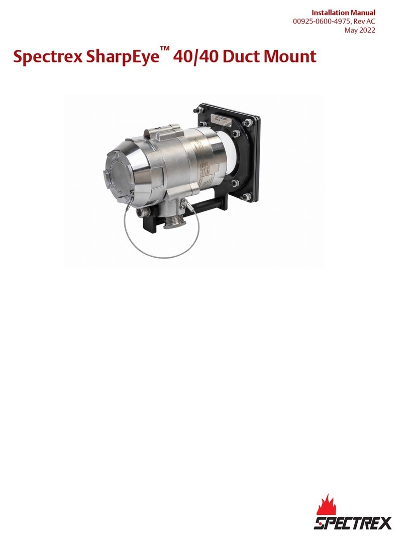
Spectrex
Spectrex SharpEye 40/40 Duct Mount installation manual

INIM Electronics
INIM Electronics PREVIDIA-CS Series instruction manual

Notifier
Notifier NBG-12LX quick start guide
Honeywell
Honeywell Notifier LCD2-80 instruction manual

Zeta Alarm Systems
Zeta Alarm Systems Premier Quatro QT/4P User manual, maintenance guide & log book
