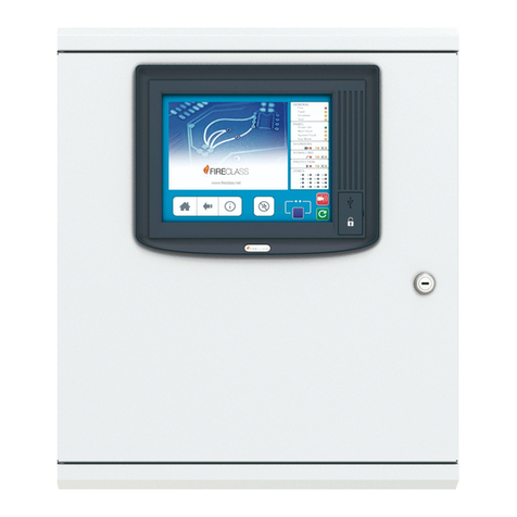
Johnson Controls IFC-1010 User manual

IFC-1010/2020 Technical Manual 448
Hardware Installation Section
Technical Bulletin
Issue Date 0500
© 2000 Johnson Controls, Inc. 1
Code No. LIT-448155 www.johsoncontrols.com
Safety Guidelines Page 5
•Installation Precautions 5
•Fire Alarm System Limitations 7
•FCC Warning 8
Introduction 9
•Location of Content Changes 9
•Supported Products 9
•Capabilities and Capacities 9
•Fire Alarm and Related Service Standards 11
Installation Overview 13
•Basic Equipment 13
•Related Documentation *13
Cabinet and Component Installation 15
•General 15
•Product Line Information 15
•Prior To Installation 15
•Left Mount 16
•Mounting the Backbox 16
•Door Assembly Instructions 17
•CAB-3 Series Backboxes 19
•Mounting the ICA-4L 21
•Component Placement 27
Installing the IFC-1010/2020
*Indicates those sections where changes have occurred since the last printing.

2Hardware Installation—Installing the IFC-1010/2020
•Optional Chassis Mounting Page 34
•Other Components 34
•Display Interface Connection *36
Power Supplies 41
•AC Primary Power Input 41
•MPS-24A or MPS-24AE Main Power Supply *42
•Mounting the Main Power Supply *51
•MPS-TR Main Power Supply Monitor *52
•Connecting the Main Power Supply *55
•Optional Main Power Meter 59
•NR45-24 Remote Battery Charger 60
•Connecting the Primary Power Source 60
•CHG-120 Remote Battery Charger *61
•AVPS-24 or AVPS-24E Audio/Visual Power Supply *63
•APS-6R Auxiliary Power Supply *64
•Central Processing Unit (CPU-2020, CPU-2) 68
Signaling 71
•LIB Signaling Line Circuit 71
•Loop Interface Boards (LIB-200, LIB-200A, and LIB-400) *72
•LIB SLC Loop Wiring Requirements *75
•SLC Loop Shield Termination 82
•Isolator Module 82
•Monitor Modules *84
•Control Module *92
•Installation 99
•Smoke Detector Installation 101
•XP Series Transponder 105
*Indicates those sections where changes have occurred since the last printing.*Indicates those sections where changes have occurred since the last printing.

Hardware Installation—Installing the IFC-1010/2020 3
Serial Communications Page 107
•Optional Serial Interface Boards *107
•CRT-2 Terminal 111
•Remote Printers *113
•Annunciator Modules *117
Standard-Specific Requirements 123
•System Components *123
•NFPA 72-1999 Auxiliary Fire Alarm Systems *126
•Generating Event-Pending Signals at a Remote Location 127
•Supervising an Uninterruptable Power Supply 128
•NFPA 72-1999 Proprietary Fire Alarm Systems *129
•Fire Alarm and Trouble Signal Transmission *131
•Applying/ Removing Power to the Fire Alarm System 132
Application and Clarification Notes *133
*Indicates those sections where changes have occurred since the last printing.

4Hardware Installation—Installing the IFC-1010/2020

Hardware Installation—Installing the IFC-1010/2020 5
Safety Guidelines
Adherence to the following will aid in problem-free installation with
long-term reliability:
!
WARNING: Several different sources of power can be
connected to this Fire Alarm Control Panel
(FACP). Disconnect all sources of power before
servicing. Control unit and associated equipment
may be damaged by removing and/or inserting
cards, modules, or interconnecting cables while the
unit is energized. Do not attempt to install, service,
or operate this unit until this manual is read and
understood.
!
CAUTION: System Reacceptance Test after Software Changes:
To ensure proper system operation, this product must
be tested in accordance with the National Fire
Protection Agency (NFPA) NFPA 72-1997
Chapter 7 after any programming operation or change
in site-specific software. Reacceptance testing is
required after any change, addition or deletion of
system components, or after any modification, repair,
or adjustment to system hardware or wiring.
•All components, circuits, system operations, or software functions
known to be affected by a change must be 100% tested. In addition, to
ensure that other operations are not inadvertently affected, at least 10%
of initiating devices that are not directly affected by the change, up to a
maximum of 50 devices, must also be tested and proper system
operation verified.
•This system meets NFPA requirements for operation at 0-49ºC and at a
relative humidity of 85% RH (non-condensing) @ 30ºC. However, the
useful life of the system’s standby batteries and the electronic
components may be adversely affected by extreme temperature ranges
and humidity. Therefore, it is recommended that this system and its
peripherals be installed in an environment with a nominal room
temperature of 60-80ºF. N30
Installation
Precautions

6Hardware Installation—Installing the IFC-1010/2020
•Verify that wire sizes are adequate for all initiating and indicating
device loops. N25 Most devices cannot tolerate more than a 10% I.R.
drop from the specified device voltage.
•Like all solid-state electronic devices, this system may operate
erratically or can be damaged when subjected to lightning induced
transients. Although no system is completely immune from lightning
transients and interferences, proper grounding will reduce
susceptibility. Overhead or outside aerial wiring is not recommended,
due to an increased susceptibility to near lightning strikes. Consult
technical support if any problems are anticipated or encountered.
•Disconnect AC power and batteries prior to removing or inserting
circuit boards. Failure to do so can damage circuits.
•Remove all electronic assemblies prior to any drilling, filing,
reaming, or punching of the enclosure. When possible, make all cable
entries from the sides or rear. Before making modifications, verify that
they will not interfere with battery, transformer, and printed circuit
board location.
•Do not tighten screw terminals more than 9 lb.in. Overtightening
may damage threads, resulting in reduced terminal contact pressure
and difficulty with screw terminal removal.
•This system contains static-sensitive components. Always ground
yourself with a proper wrist strap before handling any circuits so that
static charges are removed from the body. Use static suppressive
packaging to protect electronic assemblies removed from the unit.
•Follow the instructions in the installation, operating, and programming
manuals. These instructions must be followed to avoid damage to the
control panel and associated equipment. FACP operation and
reliability depend upon proper installation.

Hardware Installation—Installing the IFC-1010/2020 7
While installing a fire alarm system may make lower insurance rates
possible, it is not a substitute for fire insurance.
•An automatic fire alarm system, typically made up of smoke
detectors, heat detectors, manual pull stations, audible warning
devices, and a fire alarm control with remote notification capability
can provide early warning of a developing fire. Such a system,
however, does not assure protection against property damage or loss of
life resulting from a fire.
•Any fire alarm system may fail for a variety of reasons:
•Smoke detectors may not sense fire where smoke cannot reach the
detectors such as in chimneys, in walls, or roofs, or on the other side of
closed doors. Smoke detectors also may not sense a fire on another
level or floor of a building. A second floor detector, for example, may
not sense a first floor or basement fire. Furthermore, all types of smoke
detectors - both ionization and photoelectric types, have sensing
limitations. No type of smoke detector can sense every kind of fire
caused by carelessness and safety hazards like smoking in bed, violent
explosions, escaping gas, improper storage of flammable materials,
overloaded electrical circuits, children playing with matches, or arson.
IMPORTANT: Smoke detectors must be installed in the same
room as the control panel and other control units
and in rooms used by the system for the connection
of alarm transmission wiring, communications,
signaling, and/or power. If detectors are not so
located, a developing fire may damage the alarm
system, crippling its ability to report a fire. N1
•Audible warning devices such as bells may not alert people if these
devices are located on the other side of closed or partly open doors or
are located on another floor of a building.
•A fire alarm system will not operate without any electrical power. If
AC power fails, the system will operate from standby batteries only for
a specified time.
•Rate-of-Rise heat detectors may be subject to reduced sensitivity
over time. For this reason, the rate-of-rise feature of each detector
should be tested at least once per year by a qualified fire protection
specialist.
•Equipment used in the system may not be technically compatible
with the control. It is essential to use only equipment listed for service
with your control panel.
Fire Alarm
System
Limitations

8Hardware Installation—Installing the IFC-1010/2020
•Telephone lines needed to transmit alarm signals from a premise to a
central monitoring station may be out of service or temporarily
disabled.
The most common cause of fire alarm malfunctions, however, is
inadequate maintenance. All devices and system wiring should be tested
and maintained by professional fire alarm installers following written
procedures supplied with each device. System inspection and testing
should be scheduled monthly or as required by national and/or local fire
codes. Adequate written records of all inspections should be kept.
!
WARNING: This equipment generates, uses, and can radiate radio
frequency energy if not installed and used in
accordance with the instruction manual, may cause
interference to radio communications. It has been
tested and found to comply with the limits for Class A
computing device pursuant to Subpart B of Part limits
for Class A computing device pursuant to Subpart B
of Part 15 of FCC Rules, which is designed to provide
reasonable protection against such interference when
operated in a commercial environment. Operation of
this equipment in a residential area is likely to cause
interference, in which case the user will be required to
correct the interference at his own expense.
Le Present apparell numerique n’emet pas de bruits radioelectriques
depassant les limites applicables aux appareils numeriques de la classe A
prescrites dans le Reglement sur le brouillage radioelectrique edicte par le
ministere des Communications du Canada.
FCC Warning
Canadian
Requirements

Hardware Installation—Installing the IFC-1010/2020 9
Introduction
The product that this document supports is UL (Underwriters
Laboratories) Multiple Listed, which requires that the content of the
documentation inherited from the manufacturer remain intact. Minor
changes clarify information such as vendor-specific product names and
literature names and numbers. More significant changes to the original
technical content, such as additions or corrections, are identified with
Note Numbers Nx. For the Note Number content, refer to the Application
and Clarification Notes section at the end of this document.
This document may contain references to some features that are not
supported before Metasys® Release 9.01. If you are using earlier firmware
releases, please ignore references to the following products:
•NAM-232
•LIB-200A
•LIB-400
•SIB-2048A
Also, the AVPS-24 and AVPS-24E have been replaced by the APS-6R.
The IFC-1010/2020 is an Intelligent Analog Addressable Combination
Fire Alarm/Security Control Panel capable of supporting the following:
Photoelectric, ionization, and thermal (heat) detectors.
Pull Stations and modules that monitor any conventional normally open
contact type devices (four wire smoke detectors, heat detectors, pull
stations, supervisory switches, water flow switches) or any normally
closed contact type device, such as a door contact that may be used in
security applications.
Modules that can supervise and switch power to notification appliances or
serve as Form-C control relays.
Notification appliance power is provided by the main power supply.
Additional notification appliance power may be provided by optional
power supplies.
Location of
Content
Changes
Supported
Products
Capabilities
and Capacities
Intelligent
Detectors
Addressable
Initiating
Devices
Addressable
Notification
Devices
Notification
Appliance Power

10 Hardware Installation—Installing the IFC-1010/2020
Prerecorded or live voice alarm messages can be dispatched through an
audio message generator. A fire fighters master telephone unit allows
communication between the control panel and fire fighters telephones
installed throughout the system.
Audio power is provided by several sizes of audio amplifiers for use in
voice alarm applications.
An IFC-1010/2020 system can support remotely mounted video display
units, printers, and serial annunciators.
IFC-2020 maximum addressable device capacity (ten LIB-200 modules):
990 Intelligent photoelectric, ionization, and thermal (heat) detectors.
+ 990 Addressable pull stations, monitor modules, control modules, and XP Transponder
circuits
= 1980 Addressable Devices system wide.
IFC-1010 maximum addressable device capacity (four LIB-200 modules):
396 Intelligent photoelectric, ionization, and thermal (heat) detectors.
+ 396 Addressable pull stations, monitor modules, control modules, and XP Transponder
circuits
= 792 Addressable Devices system wide.
The following are general terms and their associated specific part numbers
in this manual:
•PRN PRN-4
•CRT CRT-2
Voice
Evacuation
Functions
Audio Amplifier
Power
Peripherals
IFC-2020
Maximum
Addressable
Device Capacity
(ten LIB-200
modules)
IFC-1010
Maximum
Addressable
Device Capacity
(four LIB-200
modules)

Hardware Installation—Installing the IFC-1010/2020 11
It is imperative the installer understand the requirements of the Authority
Having Jurisdiction (AHJ) and review the following documents for
applicability:
•NFPA 72 National Fire Alarm Code 1993
•NFPA 90A Air Conditioning and Ventilating Systems - 1993
•NFPA 92A Smoke Control Systems - 1988
•NFPA 92B Smoke Management Systems in Malls, Atria,
Large Areas - 1991
•UL 916 Energy Management Systems
•UL 1076 Proprietary Burglar Alarm Units and Systems
•UL 1610 Central Station Burglar Alarm Units
•CAN/ULC - S527 - M87 Standard for Control Units for Fire Alarm
Systems
•EIA-232E Serial Interface Standard
•EIA-485 Serial Interface Standard
•NEC Article 300 Wiring Methods
•NEC Article 760 Fire Protective Signaling Systems
•UL 38 Manually Actuated Signaling Boxes
•UL 217 Smoke Detectors, Single and Multiple Station
•UL 228 Door Closers-Holders for Fire Protective Signaling Systems
•UL 268 Smoke Detectors for Fire Protective Signaling Systems
•UL 268A Smoke Detectors for Duct Applications
•UL 346 Waterflow Indicators for Fire Protective Signaling Systems
•UL 464 Audible Signaling Appliances
•UL 521 Heat Detectors for Fire Protective Signaling Systems
•UL 864 Standard for Control Units for Fire Protective Signaling
Systems
•UL 1481 Power Supplies for Fire Protective Signaling Systems
•UL 1638 Visual Signaling Appliances
•CAN/ULC - S524 - M91 Standard for Installation of Fire Alarm
Systems
•Local and state building codes
Fire Alarm and
Related Service
Standards

12 Hardware Installation—Installing the IFC-1010/2020

Hardware Installation—Installing the IFC-1010/2020 13
Installation Overview
The basic equipment package for the Johnson Controls IFC-2020 is the
BE-2020 and the basic equipment package for the Johnson Controls
IFC-1010 is the BE-1010. The following list may be used to identify
various components in a received BE-2020 and/or BE-1010 shipment.
Refer to Circuit/Device Ratings and Connections Technical Bulletin
(LIT-448160) for an optional equipment listing.
•cables
- MPS to ICB Power Cable (71030 or 75378)
- CPU/MPS Supervisory Cable (71031)
•BP-3 Battery Dress Panel
•CPU-2020(BE-2020) or CPU-2 (BE-1010) Central Processor Unit
•DIA-1010 or DIA-2020 Display Interface Assembly
- CPU to DIB cable (75226) N11
•ICA-4L Interconnect Chassis Assemblies
To obtain a complete understanding of specific features within the
IFC-1010/2020 or to become familiar with functions in general, make use
of the documentation noted in Table 1 or use the VeriFire™ Windows®
based offline programming and test utility, which reduces installation
programming time.
Table 1: Related Documentation
Document FAN or LIT Number
IFC-1010/2020 Technical Manual FAN 448
500 Series Intelligent Modules Technical Bulletin LIT-408100
LCD-80 Liquid Crystal Display Technical Bulletin LIT-445151
Device Compatibility Technical Bulletin LIT-445180
NIB-96 Network Interface Board Technical Bulletin LIT-445101
LDM Lamp Driver Modules Technical Bulletin LIT-445161
Installing the Fire Fighters Command Center Technical
Bulletin
LIT-448165
XP5 Series Transponders Technical Bulletin LIT-445230
Basic
Equipment
Related
Documentation

14 Hardware Installation—Installing the IFC-1010/2020

Hardware Installation—Installing the IFC-1010/2020 15
Cabinet and Component
Installation
The cabinet assembly consists of two basic components; the backbox
(SBB) and door (DR). All cabinets for the IFC-1010/2020 are fabricated
from 16-gauge steel.
Cabinet parts are painted gray or red with navy blue windows.
Provided with the key-locked door are a pin-type hinge, window,
two keys, and the necessary hardware to mount the door to the backbox.
The backbox has been engineered to provide ease-of-entry, with knockouts
positioned at numerous points to simplify conduit installation.
The hinges are field-selectable for either left or right mounting. The door
opens 180 degrees.
Cabinets are available in sizes A through D. N2
A trim ring (TR) option is available for semi-flush mounting
(TR-A3, TR-B3, TR-C3, TR-D3).
A wire channel (WC-2) option provides a pair of wire trays to neatly route
wire between tiers in the cabinet. Order one pair per cabinet tier. N9
The doors may be mounted in either a left or right opening configuration;
aiding in installation and service when two control panels are mounted in a
confined area or side-by-side (as shown in Figure 1). In this manner the
doors may be opened barn door style, creating an open workspace. Note
that in this type of installation it is necessary to leave enough space
between cabinets to insert a key into the locks on the door frames.
General
Product Line
Information
Prior to
Installation

16 Hardware Installation—Installing the IFC-1010/2020
On a left mounted door, the Display Interface Assembly (DIA) dress panel
cannot be opened when the door is at less than a 120 degree angle to the
cabinet. If you are using the left mounting option, be sure that the door can
open at least 120 degrees. This is especially important if the cabinet is to
be mounted in a closed area, such as a closet or utility room.
irdoor
Left
Mounted Door
Right
Mounted Door
Figure 1: Mounting Cabinet Doors
Note: The two hinges and the two alignment tabs should be attached to
the backbox before any equipment is mounted in the backbox. N4
The cabinet may be either surface mounted or semi-flush mounted (refer to
Figure 2). Mount the cabinet in a clean, dry, vibration-free area, using the
four holes provided in the back surface of the backbox. Locate the cabinet
so that the top edge is 66 inches above the surface of the finished floor.
This procedure places the center of the control panel keypad 60 inches
above the finished floor.
Cabinet
Mounting
Holes
backmnt
Figure 2: Cabinet Backbox Mount
Left Mount
Mounting the
Backbox

Hardware Installation—Installing the IFC-1010/2020 17
!
CAUTION: Unless you are familiar with the placement of
components within this backbox, use only the
knockout locations provided for conduit entry. N5
Hinges can be either left or right mounted. The illustrations and text depict
a left-mount example. For right mounting, simply substitute right for left
in the instructions.
1. Insert door hinges (A) into the top and bottom slots of the side to be
hinged (in this case the left side). Secure the hinges to the studs in the
backbox with the nuts provided. Note that the small hole on the outer
tab faces outward.
2. Thread stud (B) into the bottom hinge first. Thread from the bottom
up. Place the grounding star washer on the stud. Place the door’s
lower corner onto this stud. Placing the door on the lower stud first
provides a place for the door to rest while completing the assembly.
3. Align the door on the backbox, so that the door sits directly under the
top hinge. Thread remaining stud (B) into the top hinge and through
the hole in the top of the door. The door should now swing freely.
doorasy1
Top Left
Corner
Small Hole
Faces Outward
A
B
Figure 3: Door Assembly–Top Left Corner
Door Assembly
Instructions

18 Hardware Installation—Installing the IFC-1010/2020
doorasy2
Star Washer
Bottom
Left Corner
B
A
Figure 4: Door Assembly–Bottom Left Corner
4. Install the door alignment tabs (C) in the unused slots on the backbox
(top and bottom) as shown in Figure 5. (In this example the door was
mounted on the left, leaving the unused slots on the right). Secure
alignment tab (C) to top PEM stud with nut provided. These tabs align
the door correctly with the backbox.
doorasy3
C
Figure 5: Door Assembly–Alignment Tab
Note: The installation is the same for the top and the bottom right corner
of the backbox.
5. Punch out the knockout for the door lock on the side opposite the
hinge and install the lock mechanism as shown in Figure 6.

Hardware Installation—Installing the IFC-1010/2020 19
drlock
Open
Locked
Install
Lock Here
The lock mechanism as viewed in a
left-hinged mounting application.
The lock world be placed in the
right side of the door
(as shown below).
Figure 6: Mounting the Lock
The CAB-A3 is the cabinet and door assembly for one mounting tier. N9
An optional TR-A3 trim ring is available for use with the A-size cabinet
(24.125 in. width by 20.125 in. height). The following replacement parts
are available:
•DR-A3 door
•SBB-A3 backbox
24.125
20.125
24.00
19.502.250
4.0 16.00
11.281
1.625
0.3125
diameter 0.3125
diameter
20.00
2.060
8.625
2.562
5.218
caba3
Figure 7: CAB-A3 N32
CAB-3 Series
Backboxes
CAB-A3

20 Hardware Installation—Installing the IFC-1010/2020
The CAB-B3 is the cabinet and door assembly for two mounting tiers. N9
An optional TR-B3 trim ring is available for use with the B-size cabinet
(24.125 in. width by 28.625 in. height). The following replacement parts
are available: DR-B3 door and SBB-B3 backbox.
24.125
28.625
24.00
19.502.250
4.0 16.00
19.781
1.625
28.50
2.060
8.625
8.625
2.562
5.218
cabb3
0.3125
diameter
0.3125
diameter
Figure 8: CAB-B3 N32
The CAB-C3 is the cabinet and door assembly for two mounting tiers. N9
An optional TR-C3 trim ring is available for use with the C-size cabinet
(24.125 in. width by 37.250 in. height). The following replacement parts
are available: DR-C3 door and SBB-C3 backbox.
24.125
37.250
24.00
4 .0 16.00
28.404
37.125
2.060
8.625
8.625
8.625
1.625 5.218
cabc3
19.50
2.250
0.3125
diameter
0.3125
diameter
Figure 9: CAB-C3 N32
CAB-B3
CAB-C3
Other manuals for IFC-1010
1
This manual suits for next models
1
Table of contents
Other Johnson Controls Fire Alarm manuals
Popular Fire Alarm manuals by other brands

Greenheck
Greenheck Combination Fire Smoke Dampers FSD-M211 Specifications

Siemens
Siemens FDM275-O Technical manual

Notifier
Notifier INERTIA-2464/64 Technical/Programming Manual

Edwards
Edwards 2400 Series Product/Technical Bulletin

Cooper Notification
Cooper Notification ET70-24MCCH Series installation instructions

Eurofyre
Eurofyre ProFyre C8 User & Maintenance Guide + Log Book