EE Lighting AFL-180LED-50K User manual

Energy Efficient Lighting Ltd. | www.eelighting.ca | Tel: 1-855-415-8878 EEL18W36
INSTALLATION INSTRUCTIONS for LED Architectural Flood Light
AFL-180LED-50K/40K AFL-90LED-50K/40K
Li
ght
in
g
WARNING
RISK OF ELECTRIC SHOCK.
Make sure power supply is OFF before installing or maintaining fixture. No user serviceable parts inside.
Never perform maintenance or cleaning while fixture is energized. Disconnect power and allow fixture to cool before maintaining.
MOUNTING
WIRING
1.Wire input end of the LED driver to supply wires according to wiring section.
Wire connections must be insulated and waterproof.
2.Connect the BLACK/BROWN lead to LINE (+) supply lead.
3.Connect the WHITE/BLUE lead to NEUTRAL/COMMON (-) supply lead.
4.Connect the GREEN lead to GROUND supply lead.
5.If any, connect PURPLE/BLUE to 0-10V SIGNAL supply lead and
GREY/WHITE to 0-10V NEUTRAL/REFERENCE supply lead.
IMPORTANT
READ CAREFULLY BEFORE INSTALLING THE FIXTURE. KEEP THESE INSTRUCTIONS FOR FUTURE REFERENCE.
This product MUST be installed in accordance with the applicable installation code by a person familiar with the construction and operation of the product.
Proper grounding is required for safety. This product shall be mounted above 4 feet (1.2meter) high and at least 18” (46 centimeter) below any overhang or other
User should prepare necessary accessories and spare parts (not provided) including junction box and screws.
CAUTION
RISK OF
ELECTRIC SHOCK
· DISCONNECT POWER BEFORE INSULATING
OR SERVICING
· ALL ELECTRICAL WORK SHOULD BE
COMPLETED BY QUALIFIED PERSONNEL
AND MEET NATIONAL (NEC), REGIONAL AND
LOCAL ELECTRICAL CODES.
WIRING DIAGRAM
ELECTRICAL
SYSTEM
0-10V DIMMING
SYSTEM (IF ANY)
BLACK/BROWN = HOT/LINE
WHITE/BLUE- NEUTRAL/COMMON
GREEN/YELLOW = GROUND
PURPLE/BLUE=0-10V SIGNAL
GREY/WHITE = NEUTRAL/REFERENCE
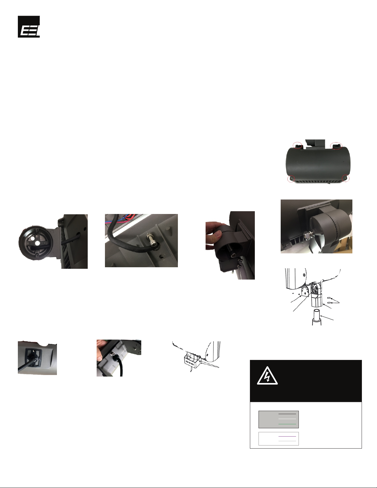
Slip Fitter
structure; this fixture SHALL NOT BE recessed.
1. Separate the slip fitter into pieces by loosening the screw, bolts and nuts. Run the input cord through the
gasket and the upper half of slip fitter (shown in Fig 2). Assemble slip fitter and gasket onto housing using 2 bolts
and washers (shown in Fig 3)
2. Run the wire through the lower half of the slip fitter and assemble it onto the upper half using a bolt,
nuts and washers. (shown in Fig 4 and Fig 5)
3. Install the cover plate back to the slip-fitter using screws. Gasket should be applied to seal it properly.
4. Slip lower half of the slip fitter over tenon and securely tighten two allen head set screws. (shown in Fig 6)
5. The slip fitter is designed to be installed on a 2-3/8” o.d. heavy wall pipe or tenon.
Fig 2. Fig 3.
Fig 5.
Fig 4.
Trunnion
1. Run the input cord through the gasket and the cable gland, then tighten
the cable gland firmly. (shown in Fig 7)
2, Assemble the trunnion mount bracket onto the fixture using 2 bolts, nuts
and washers (shown in Fig 8)
The trunnion mount bracket offers five different positions. There are three position holes in
the outer yoke and five positioning holes in the inner yoke.
To adjust it, loosen the positioning screws and trunnion bolts, then rotate trunnion to the
desired angle. Reinsert positioning screws and tighten them. (shown in Fig 9)
Fig 7.
Fig 6.
Fig 8.
REASSEMBLY
Use screw to tighten and close the fixture.
Make sure all gaskets must be seated properly and all bolts and screws are inserted and tightened firmly.
Fig 9.
Fig 1.
This product is available in SLIP FITTER and TRUNNION as mounting options.
Follow the specific bracket installation instruction accordingly.
Open the fixture by unscrewing the 4 screws shown in Fig.1
Note: Slip fitter is required when using wall mount adaptor or round pole adaptor.
Energy Efficient Lighting Ltd. | www.eelighting.ca | Tel: 1-855-415-8878 EEL18W36
INSTRUCTIONS D'INSTALLATION Pour Le Projecteur Architectural À DEL
Li
ght
in
g
MONTAGE
Ce produit est offert avec un MONTAGE À RACCORD LISSE et un MONTAGE À TOURILLON,
et son modèle standard comporte un support pour montage à raccord lisse. Suivre les instructions d'installation spécifiques pour le bon type de montage.
Montage À Raccord Lisse
IMPORTANT
LIRE ATTENTIVEMENT AVANT D'INSTALLER LE LUMINAIRE. CONSERVER CES INSTRUCTIONS À DES FINS DE RÉFÉRENCES.
Ce produit DOIT être installé conformément au code d'installation applicable par une personne familière avec le
La construction et l'exploitation du produit. Les appareils doivent être câblés conformément au Code national de l'électricité et à tous les codes locaux applicables.
Mise à la masse appropriée. Est nécessaire pour la sécurité.
ATTENTION
RISQUE DE DÉCHARGE ÉLECTRIQUE.
S'assurer que l'alimentation principale est HORS CIRCUIT avant d'installer ou d'entretenir le luminaire. Ne jamais effectuer l'entretien
ou le nettoyage alors que le luminaire est sous tension. Couper l'alimentation et laisser l'appareil refroidir avant l'entretien.
AFL-180LED-50K/40K AFL-90LED-50K/40K
RÉASSEMBLAGE
Utiliser les vis pour fermer et fixer le luminaire.
S'assurer que tous les joints d'étanchéité soient bien placés, et que tous les boulons
FILAGE
1.Filer l'entrée du circuit d'entraînement de DEL pour amener les fils
conformément à la section sur le filage. Les connexions des fils doivent être isolés et étanches.
2.Connecter le fil NOIR/BRUN au fil d'alimentation LIGNE (+).
3.Connecter le fil BLANC/BLEU au fil d'alimentation NEUTRE/COMMUN (-).
4.Connecter le fil VERT au fil de MISE À LA TERRE.
5.Le cas échéant, connecter le fil MAUVE/BLEU au fil de SIGNAL 0-10 V,
et le fil GRIS/BLANC sur le fil de NEUTRE/RÉFÉRENCE 0-10 V.
ATTENTION
RISQUE DE
DÉCHARGE ÉLECTRIQUE
·
OU L'ENTRETIEN
COUPER LE COURANT AVANT L'ISOLATION
·
EFFECTUÉ PAR DU PERSONNEL QUALIFIÉ ET
RÉPONDRE AUX CODES D'ÉLECTRICITÉ
RÉGIONAUX ET LOCAUX (NEC).
TOUT LE TRAVAIL ÉLECTRIQUE DOIT ÊTRE
DIAGRAMME GÉNÉRAL DE CÂBLAGE
ELECTRICAL
SYSTEM
0-10V DIMMING
SYSTEM (IF ANY)
NOIR/BRUN = CHAUDE/LIGNE
BLANC/BLEU- NEUTRE/COMMUN
VERT/JAUNE = MISE À LA TERRE
VIOLET/BLEU=0-10V SIGNAL
GRIS/BLANC= NEUTRAL/REFERENCE
et les vis sont insérées soient serrés solidement.
Une mise à la terre adéquate est requise à des fins de sécurité. Ce produit doit être installé à plus de 1,2 m (4 pi) de hauteur et à au moins 46 cm (18 po) au-
dessous de tout porte-à-faux ou de toute autre structure; ce luminaire NE DOIT PAS être encastré.
Dévisser les 4 vis comme il est indiqué à la figure 1 pour ouvrir le luminaire.
1. Séparer le domino en deux en desserrant la vis, les boulons et les écrous. Acheminer le cordon d'entrée à
travers le joint et la moitié supérieure du domino (indiqué à la figure 2). Assembler le domino et le joint dans le
boîtier à l'aide de 2 boulons et les rondelles (indiqué à la figure 3).
2. Faire passer le fil dans la moitié inférieure du domino et l'assembler sur la moitié supérieure à l'aide d'un
boulon, des écrous et des rondelles (indiqué aux figures 4 et 5).
3. Remettre le couvercle en place sur le domino à l'aide des vis. Le joint doit être apposer pour le sceller
correctement.
4. Faire glisser la partie inférieure du domino sur le tenon et serrer fermement les deux vis à six pans creux
(indiqué à la figure 6).
5. Le domino est conçu pour être installé sur un tuyau ou un tenon à paroi épaisse de 60,32 mm (2 3/8 po). Fig 5.
Fig 1.
Fig 2. Fig 3. Fig 4.
Fig 6.
Plaque de couverture
Boulon de verrouillage
Tenon
Montage À Raccord Lisse
Vis de Pression
Trunnion
1. Faire passer le cordon d'entrée à travers le joint et le presse-étoupe, puis serrer fermement
le presse-étoupe (indiqué à la figure 6).
2. Assembler le support de montage du tourillon sur le luminaire en utilisant 2 boulons, les
écrous et les rondelles (indiqué à la figure 7).
Le support de montage du tourillon comporte cinq positions différentes. Il y a trois trous de
position dans la fourche extérieure et cinq trous de position dans la fourche intérieure.
Pour le régler, il suffit de dévisser les vis de positionnement et les boulons de tourillon, puis
faire pivoter le tourillon à l'angle souhaité. Réinsérer les vis de positionnement et les serrer
(indiqué à la figure 8).
Fig 7. Fig 8. Fig 9.
Boulons pivot
This manual suits for next models
3
Table of contents
Languages:
Other EE Lighting Floodlight manuals


