D 12 E 09
11 0 255
12
000 200
201 220
221 255
CHANNEL FUNCTIONVALUE
7
8
0 9
١~Hz٢٠
10 255
0 255
9
231 235
236 240
241 245
246 250
251 255
WHITE ٧: ٦٥٠٠K
WHITE ٨: ٧٢٠٠K
WHITE ٩: ٨٠٠٠K
WHITE ١٠: ٨٥٠٠K
WHITE ١١: ١٠٠٠٠K
6
DIMMER SP EED
LINEAR DIMMER
NON LINEAR DIMMER 1£fastest£
10 29
30 69
70 129
130 189
190 255
10
NON LINEAR DIMMER 2
NON LINEAR DIMMER 3
NON LINEAR DIMMER 4£slowest£
NO FUNCTION
AUTO
NO FUNCTION
STROBE
AUTO SPEED ADJUSTMENT
When using CH8,AUTO01-AUTO10, this function activated
0 9 PRESET DIMMER SPEED FROM DISPLAY MENU
ZOOM
NO FUNCTION
ZOOM RESET
NO FUNCTION
141 150
151 160
161 170
171 180
181 190
191 200
201 210
211 220
221 230
PR.01
231 255
91 100
101
110
111 120
121 130
٦ AUTO
٧ AUTO
٨ AUTO
٩ AUTO
131 140 AUTO ١٠
0 40
41 50
51 60
61 70
71 80
81 90
AUTO 1
AUTO 2
٣ AUTO
٤ AUTO
٥ AUTO
PR.02
PR.03
PR.04
PR.05
PR.06
PR.07
PR.08
PR.09
PR.10
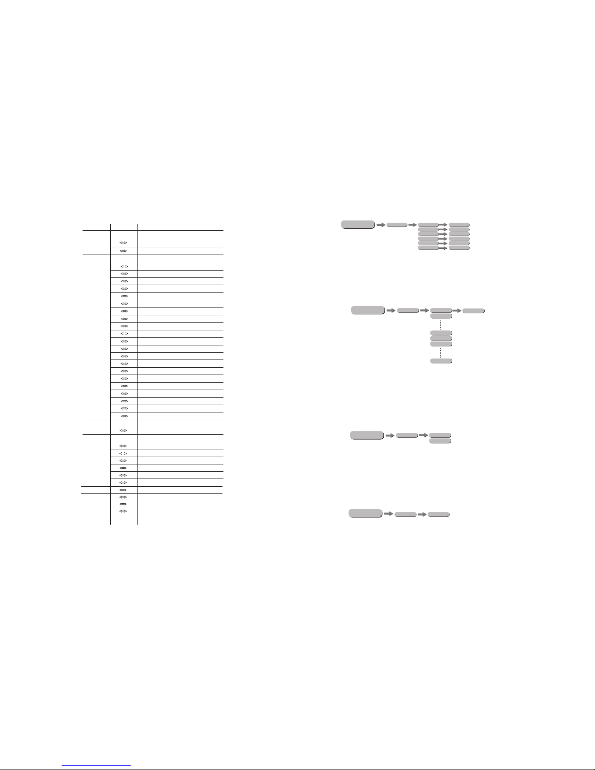
MENU
SET
UPLD
REST
OFF
COLR
DIM3
DIM1
DIM2
DIM4
DIMX
RGBW
UC
OFF
PASS
PASS
SEND OK
REST O K
BLAK
SAVE
DERR
POS2
POS1
ZOOM BASE
KEY ON
OFF
ON
OFF
SLCK
¡[SET]...this menu allows the user to adjust key operation settings for this fixture.
[KEY]...select [ON] for automatic lock-out. Password to re-enter the display is <UP>
+ <DOWN> + <UP> + <DOWN>.
¡ Select UPLD to upload the custom programs from the current MASTER unit to the [ ]
SLAVE units.
¡ In order to reset custom modes to default values select REST .[ ]
¡ COLR is for activate/unactivate the color calibration functions. When RGBW is [ ] [ ]
selected, on RGB = 255,255,255, the color is displayed as calibrated
in CAL2 -- RGBW. When COLR is set OFF , on RGB = 255,255,255, the [ ] [ ]
RGBvalues are not adjusted and the output is most powerful.When [UC] is
selected, the RGB output are adjusted to a standard preset universal color which
balances fixtures from different generations.
¡ Select [DIM1], [DIM2], [DIM3] or [DIM4] for different dimming speeds. ([DIM4]is the
slowest dimming speed)
¡DERR hoose Save in order to save the last DMX data incase of DMX signal error.[ ] C [ ]
Choose Black in order to blackout in case of DMX signal error. [ ]
¡[SLCK] is used to lock the settings menu. When [SLCK] is set to [ON] then user must
insert passcode (UP+DOWN+UP+DOWN) in order to access the settings menu.
¡ ZOOM Calibrate the position of POS1&POS2.Set position as 0 for smallest zoom [ ]
position. selecf BASE for defaulf zoom position (zoom=0)
3.27 SPECIAL SETTINGS