EECI ADC-4U15 Use and care manual
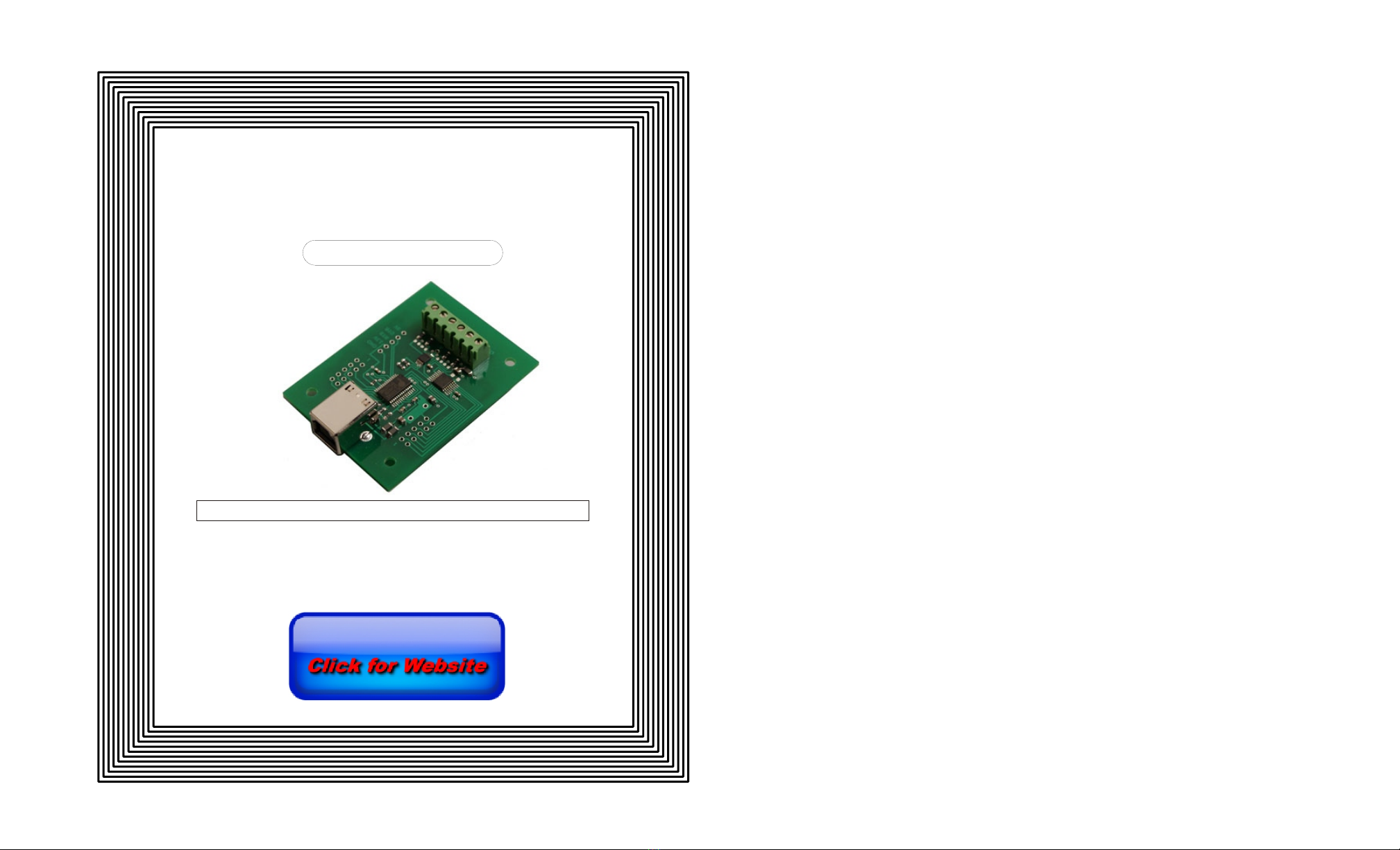
TABLE OF CONTENTS
Specifications.......................................... page 1
Connection Diagram and Warranty......... page 2
Technical Support................................... page 2
Terminal Block Connections.................... page 2
Set-Up and Testing................................. page 3 & 4
Device Manager...................................... page 4
Trouble-Shooting and Sample Rate........ page 5
Input & Relay Expansion Ports............... page 5
The ADC-4U15 User Interface................ page 6
Auto Start-Up.......................................... page 6
The ADC-4U15 Data Logger................... page 7
Programming Examples......................... page 7
Voltage Reference for the analog inputs. page 8
Single Ended Analog Inputs.................... page 8
Analog Scaling and Differential Inputs.... page 9
Input Amplification and Conditioning..... page 11
Voltage Inputs and Sensor Interfacing.....page 10 & 11
Mounting..................................................page 11
SPECIFICATIONS
Power Supply....................... 5 volts DC - powered from USB port (USB version only)
Operating Temp. Range...... -40° C to +85° C
Serial Data Protocol............. 75 to 6,000,000 baud - auto detect (defaults to 115,200 baud)
Full duplex operation (data bits, parity, stop bits will auto detect)
Maximum Sampling Rate...... 100 samples per second or better
Analog Inputs....................... 4 single-ended inputs (15 bit resolution) - no missing codes
or 2 fully differential inputs (16 bit resolution) - no missing codes
(15 bit resolution will divide your measurement range into 32,768 different increments)
(16 bit resolution will divide your measurement range into 65,536 different increments)
Input Impedance................. Common mode better than 6 mega ohm (see page 11 and 12)
Voltage Input Range............ Selectable at: 0 to 256 millivolt, 0 to 512 millivolt, 0 to 1.024 volt, 0 to 2.048 volts,
0 to 4.096 volts and 0 to 6.144 volts (with 5 V max)*
*the voltage resolution per increment can be determined by dividing one of the
above reference voltages by 32,768.
Expansion Capability............ expandable to control up to 144 relays/inputs (or combinations) using
EX-8M, EXM-8, EXM-16 or EXM-32 Relay I/O Expansion Modules
Interface.............................. USB (also available in WiFi version (ADC4-15WIFI), Ethernet version
(ADC4-15FENET) RS-232 version (ADC4-15RS232) or
RS-485 version (ADC4-15RS485))
Software Compatibility......... Windows XP, Vista, Windows Server, Windows 7, 8.1, Windows 10 and Windows 11
Weight................................. .5 ounce
Size...................................... 1.875 inches by 2.5 inches
Please see page 12 for additional specifications.
Page 1
TECHNICAL REFERENCE
ADC-4U15
ANALOG TO DIGITAL
CONVERTER
Click for more info: www.eeci.com/adc-4u15p.htm
(937) 349-6000
(800) 842-7714
(937) 349-6000
PHONE...................
ORDERS................
TECH SUPPORT...
E-mail.....................
www.eeci.com
(Step 2) Connect your ADC-4U15 Analog to Digital Converter to any available USB port on your computer using a
CC-USBB cable (1 to 15 foot). A high percentage of systems will be up to date and you will not see any activity or a
pop-up message (allow up to 30 seconds for any system message). If your USB Com driver is out of date, you may
receive a message that your system is being updated or a new driver is being installed. Allow the update to occur
before you move to the next step. If you do not see activity or receive a system message, proceed to step 3.
(Step 3) Insert the installation CD or USB flash drive and wait for the security message (with a USB flash drive, you
may need to browse to the drive icon from your My Computer link). OK or click the startup.exe file to start the installer
dialog.
(Step 4) Check your USB Com driver by clicking on the "Open Device Manager" button in the installer dialog window
and expanding the "Ports (COM & LPT)" category (expand the category by clicking on the + or arrow, see Device
Manager on page 5 or go directly to Device Manager from Control Panel). If you see a "Prolific USB-to-Serial Comm
Port" entry, this is your USB Com
driver* and the com port assigned is
to the right of the entry. Right click
on the entry and select
"Properties"and click the "Driver"
tab. Your USB Com driver must be
Prolific version 3.4.62.293 or higher
(dated 10/17/2013 or later). If your
USB Com driver is not up to date,
right click on the entry and select
"Update Driver Software". If your
USB Com driver is up to date then
please note the Com port number
assigned and jump to step 5.
*verify that this is the com port
assigned to the ADC-4U15 by
unplugging the ADC-4U15 from
your USB port and watching the
entry in device manager. The entry
should disappear and then reappear
when you plug the ADC-4U15 back
in.
If you do not have an Internet
connection or are having problems
with the USB Com driver installation, disconnect the ADC-4U15 USB cable from your computer and install the USB
Com driver from your CD by clicking on the "Install USB Com Driver" button. Please note that you may have to remove
any out of date Prolific Com drivers on your system before the current driver will install correctly. It is important that you
use the remove feature on your CD (not the remove feature in Device Manager). The remove feature is shown after
clicking the "Install USB Com Driver" button from the installer dialog window (allow up to 30 seconds for the installer to
load and appear).
(Step 5) After you have verified or installed the up to date USB Com driver, reconnect (if not already connected*)
your ADC-4U15 Analog to Digital Converter to the same USB port and install the ADC-4U15 device driver** by clicking
the "Install EECI Device Driver" button from the installer dialog window (if you have auto start disabled, you may
browse to the Windows Driver folder and double click on setup.exe). A desktop icon for the ADC-4U15 will be created.
When installing the ADC-4U15 device driver on a Windows XP or Vista computer, double click on setup.exe in the XP-
Vista folder. *if you reconnect your ADC-4U15 to a different USB port, a different com port may be assigned.
**Please note that the Microsoft .Net Framework must be installed on your system. The .Net Framework is already
Page 3
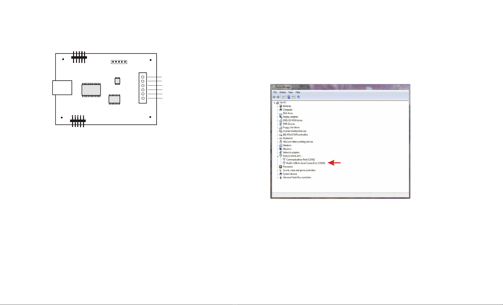
CONNECTION DIAGRAM
A D C - 4 U 1 5 A N A L O G TO
D I G I T A L C O N V E R T E R
DESCRIPTION
The ADC-4U15 Analog to Digital converters connect to any available USB port on your Windows desktop or laptop
PC (including some tablets and phones). Four analog inputs channels are provided for conversion to 15 bit digital
format. The converters may be set to two channel fully differential mode with 16 bit resolution if required. Three
optional expansion ports are available for connection of up to 144 relays, 144 status inputs or combinations of relays
and inputs.
24 HOUR TECHNICAL SUPPORT
Technical support for our products is available by calling (937) 349-6000. If a technical adviser is not available, please
leave your name, phone number and a time that you can be reached. Your call will be returned as soon as possible
and within 8 hours. Calls received during normal business hours are usually returned within minutes.
WARRANTY AND CARE OF THE ADC-4U15
The ADC-4U15 Analog to Digital Converters are warranted against factory defects for a period of 90 days from the
date of purchase. The ADC-4U15 has proven to be extremely reliable in actual operation during field tests. We
recommend that the ADC-4U15 and associated hardware be installed in a suitable enclosure (4 mounting holes are
provided on the circuit board) and that reasonable precautions be taken to protect the circuit from static discharge,
electrical storm transients and over-voltage to the inputs.
SET-UP AND TESTING
Upon receiving your ADC-4U15, you should connect and test the operation of the hardware to verify proper
operation. Please set-up and test the ADC-4U15 as follows (Windows XP*, Vista, Windows Server, Windows 7, 8.1,
Windows 10 or Windows 11) *service pack 3
(Step 1) Connect to the Internet. This permits any security or software updates to occur during installation. If you do
not have an Internet connection, you may skip this step.
Page 2
USB
Expansion Port A
Expansion Port B
AUX Header
analog input #1
analog input #2
analog ground (ref -)*
analog input #3
analog input #4
analog ground (ref -)*
*the two analog ground
terminals are tied together
and are used to connect
all four inputs
Single-ended Analog
Connections
(see page 9 for
differential connections)

HOW TO OPEN DEVICE MANAGER
Windows XP, VISTA or Windows 7: Click the Start Button (lower left of screen), then Control Panel (right side). With
the view set to classic view, small or large icons, click (or double click) the Device Manager icon. With Windows XP
you will need to click the System icon (in Control Panel) then the Hardware Tab, then the Device Manager button.
You may also use the supplied CD to open Device Manager by clicking the "Open Device Manager" button.
Windows 8.1, 10, 11 and Windows Server: Move your mouse cursor to the lower right side of your screen and click
on Settings (or use search). Click on Control Panel near the top and click on the Device Manager icon.
TROUBLE-SHOOTING THE ADC-4U15
(1) Verify that your USB com driver is installed by going to Device Manager and checking for the Prolific USB to
Serial Comm Port entry. Right click on the entry, then Properties, select the Driver tab and verify that the driver is
dated 8/15/2014 or later. If the driver is out of date, connect to the Internet and click the Update Driver button. Please
note that an out of date driver may allow the ADC-4U15 to partially function and/or with erratic operation.
(2) Verify that the Prolific USB to Serial Comm Port entry is the com port used by your ADC-4U15. You may do this by
watching the entry in Device Manager and unplugging your ADC-4U15 from your computer USB port. The entry
should disappear and then re-appear when you plug the ADC-4U15 back in to your computer USB port.
(3) Try replacing the USB cable and/or using a different USB port.
(4) Verify that the ADC-4U15 device driver is correctly installed and loaded. Click the blue 4 icon in your system
tray (bottom right) and check for the correct com port setting (should show the correct com port open). If the window
below the COM indicator shows "COM Not Found!" then a com port issue is the problem (check for another program
that may be using the com port). You may right click the taskbar at the bottom of your screen, then Task Manager to
view running applications.
.
(5) Remove the ADC-4U15 USB cable from your computer, wait 5 seconds and plug back in. Open the ADC-4U15
User Interface by clicking on the blue icon in your system tray and double click on the blue EECI logo to reset
the com port. You should see a reset message followed by a COM open indication. Click Setup and uncheck "Allow
External Commands". If this corrects the issue that you are experiencing then an external application is the problem.
(6) If erratic operation is experienced, check for loose connections at the terminal block (tug on each wire going into
the terminal block), check for short circuits caused by metal contact to the ADC circuit areas or other connected
hardware. It is normal for floating (unconnected) inputs to generate random numbers due to the high impedance.
(7) The input voltage to any of the analog inputs must not exceed the reference voltage (nor should the input go
negative with respect to the reference when not in differential mode) or erratic data may be generated on one or more
of the analog channels.
Please contact EECI Support at (937) 349-6000 if you require additional assistance or have questions.
SAMPLE RATE OF ANALOG INPUTS
All four analog inputs are updated at the same rate which you set under Setup in the ADC-4U15 User Interface. The
default setting is every 250ms with an effective sample rate of 16 samples per second (or each channel sampled four
times per second). A setting of 1000 will sample all four inputs once per second or a setting of 2500 every 2.5
seconds, etc. Use caution when making changes to this setting as a time setting too low will waste processor
resources. A setting below 10ms will degrade system performance and will not allow for any change of the analog
level due to the filter cap and decoupling resistor on the analog input (which average the signal level to reduce noise).
EXPANSION PORTS
The ADC-4U15 provides three expansion ports for additional I/O operations using the same COM port. The
expansion ports may used to connect up to 144 relays (8 per expansion port) or to connect up to 144 inputs (or
combinations of relays and inputs) using EX-8M and/or EXM-16 expansion modules. The relay output ports on the
Page 5
installed if you have Windows 7 or higher. If the .Net Framework is not installed on your computer, the installation
program will attempt to download and install the .Net Framework from the Microsoft Update website through your
internet connection. This may take 5 minutes or longer. In order for the .Net Framework to install correctly, your
computer must be up to date with Windows Update. This is especially important with Windows XP* and Vista. You may
update your computer by clicking on the start button, All Programs, Windows Update and clicking on "Check for
updates". *for XP, Service Pack 3 must be installed.
(Step 6) After the ADC-4U15 device driver is installed, the ADC-4U15 com port should be detected and a pop-up will
prompt you for the com port to be used with your ADC-4U15 A to D Converter (correct com port should be shown).You
may edit the com port if incorrect. The ADC-4U15 User Interface will now open and the label just under the COM port
indicator should show that Com port open. Please Note: When the ADC-4U15 inputs are floating (no connection) the
inputs may show random or changing values from noise picked up by the high impedance inputs. Click the "Install Help
Files" button to install important trouble-shooting and reference information before you close the installer.
(Step 7) Test your analog inputs by applying a test voltage to each input. The test voltage must be within the selected
reference voltage and of the correct polarity (the default reference voltage is 4 volts, providing a voltage input range of 0
to 4.096 volts DC). You may use the analog test circuit shown below to provide the test voltage. When using a 9 volt
smoke detector battery, use a multimeter to check for the correct voltage since the voltage can go well over the
reference voltage if the potentiometer is turned beyond 10K. The input in the ADC-4U15 User Interface should
increment from 0 to 32,767 (in 1 unit increments) as the potentiometer is turned from 0 volts to 4.1 volts.
Differential inputs may be tested using the same analog test circuit (below) except you will connect the test voltage to
inputs 1 and 2 (differential channel 1) or inputs 3 and 4 (differential channel 2). When the ADC-4U15 is set to differential
mode, the ADC-4U15 will display a range from -32,768 to +32,767 in 65,536 increments (16 bit) as the input voltage
swings from -4.1 volts to +4.1 volts. The negative side of the signal is generated by reversing the polarity of the test
signal (or reversing the battery polarity). The inputs are changed to differential mode by going to the setup window in the
ADC-4U15 User Interface.
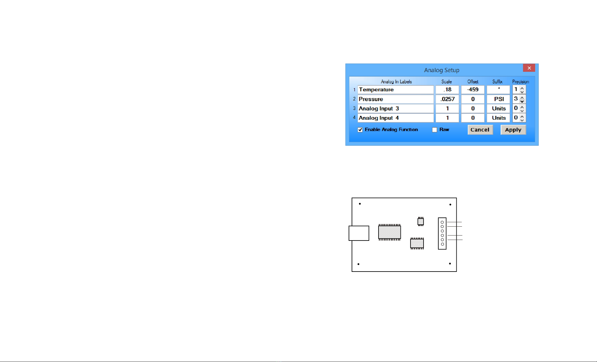
After testing is complete, you may label your analog inputs, set scale and offsets, set precision and add a suffix (such as
°, PSI, mA, etc) by going to the setup window in the ADC-4U15 User Interface and clicking the Analog Setup button. The
ADC-4U15 Data Logger may be started by checking the Enable box. The data log entry interval may be set to minutes
or seconds (click the M or S button) and entering the desired time interval. The settings will not go into effect until the
Apply button is clicked.
Click the "Tray" button to place the User Interface in "driver only" mode. You will see a blue 4 icon in your system tray by
the clock (bottom right of screen as shown below).
Click the blue 4 icon to re-open the ADC-4U15 User
Interface. Click the "Unload Device Driver" to remove the
ADC-4U15 device driver.
Please note that by default, the ADC-4U15 device driver
is only loaded on demand to conserve system resources.
To re-start the ADC-4U15 device driver, double click the
red and blue ADC-4U15 desktop icon or under Applications.
You may install the ADC-4U15 device driver permanently by checking the "Driver Only" check box under Setup in the
ADC-4U15 User Interface. You will then always see the ADC-4U15 system icon in your system tray along with the other
system devices (such as your speaker, printer or display adapter).
If operation of the analog inputs are normal, then testing is now complete and your ADC-4U15 may be placed in service.
If problems are encountered during testing, proceed to the trouble-shooting procedures shown on the following page.
Page 4
(Reference -)
To Analog Input (+)
20K Ohm
(20 turn)
Course Adjust
Analog Input Test Circuit
using potentiometers
To Analog Ground
9 Volt
Battery
(+) (-)
500 Ohm
(20 turn) Fine Adjust

*you may need to expand the arrow in your system tray to see all the icons (the tray is the row of icons on the lower
right of your screen, next to your clock).
UPDATES FOR THE ADC-4U15 DEVICE DRIVER/USER INTERFACE
Click the "Check for Updates" button under Setup in the ADC-4U15 User Interface or contact EECI support. There is
no charge for the updates.
THE ADC-4U15 DATA LOGGER
The ADC-4U15 User Interface provides a data logger function that will save analog input readings to a file at
preset time intervals. Scale and offset values may be factored into the recorded data event along with an input label
by entering the desired values at the setup screen by clicking the Analog Setup button. The ADC-4U15 data logger
may be used stand alone if an external application is not used. The file output format may be set to plain text, CSV or
text delimited formats and may be imported into database or spreadsheet applications if required. The data log
interval may be set to seconds or minutes by clicking the button to the right of the setting. A suffix may be added to
the logged value (such as PSI, Volts, °, etc.). Extended ASCII characters may be added by holding down the alt key
and entering the ASCII code on your keyboard keypad. Example: to display a degree symbol, hold down the alt key
and enter 248 on your keypad. The precision setting allows you to log your data in integer only, tenth, hundredth,
thousandth or auto select.
PROGRAMMING EXAMPLES
VISUAL BASIC EXAMPLE (Microsoft Visual Studio)
'To use these example, copy the code module (supplied on your CD) to a sub called readInputs(). From the toolbox,
drag (4) labels and a timer control to your form. Insert the following code into the timer sub. The (4) ADC-4U15
analog inputs are displayed in labels 1 through 4.
Private Sub Timer1_Tick(sender As Object, e As EventArgs) Handles Timer1.Tick
readInputs() 'collect analog inputs
For W = 1 To 4
MyLabelArray(W).Text = inputByte(W)
Next W
End Sub
VISUAL C# EXAMPLE (Microsoft Visual Studio)
private void timer1_Tick(object sender, EventArgs e)
{
ReadInputs();
for (int i = 1; i < 5; i ++)
{
MyLabelArray[i].Text = inputByte[i].ToString();
}
}
The entire source code program examples and the complete project code are provided on your installation CD along
with additional source code examples in other programming languages. The programs are intended to demonstrate
the fundamentals needed for development of your own software. The program examples may be copied to your
program and used as a subroutine if desired.
These examples will run in all versions of Visual Studio including Visual Studio Express. The installation CD will have
examples in all the programming languages used with Microsoft Visual Studio including Visual Basic, Visual C#,
Visual C++ and ASP .Net. Additional source code examples are available in several other variations which may be
more suitable for alternate programming languages. Please contact EECI technical support for more information.
Page 7
EX-8M and EXM-16 are identical to those used on all EECI products and accept the same relay cards and other
accessories. A variety of relay cards with various contact configurations are available for connection to the expansion
modules. A partial list of relay cards includes the RD-8, RD-8M, RG-8, RH-8, RI-8, RJ-8, RL-8, RN-8, RN-8M, RP-8
and RJ-8. The RYD-8 relay driver card may be used to control larger power relays, contactors, solenoids, valves or
other devices. A Digital to Analog converter may be used to output an analog voltage. For additional information
please visit t the EECI web site (at www.eeci.com).
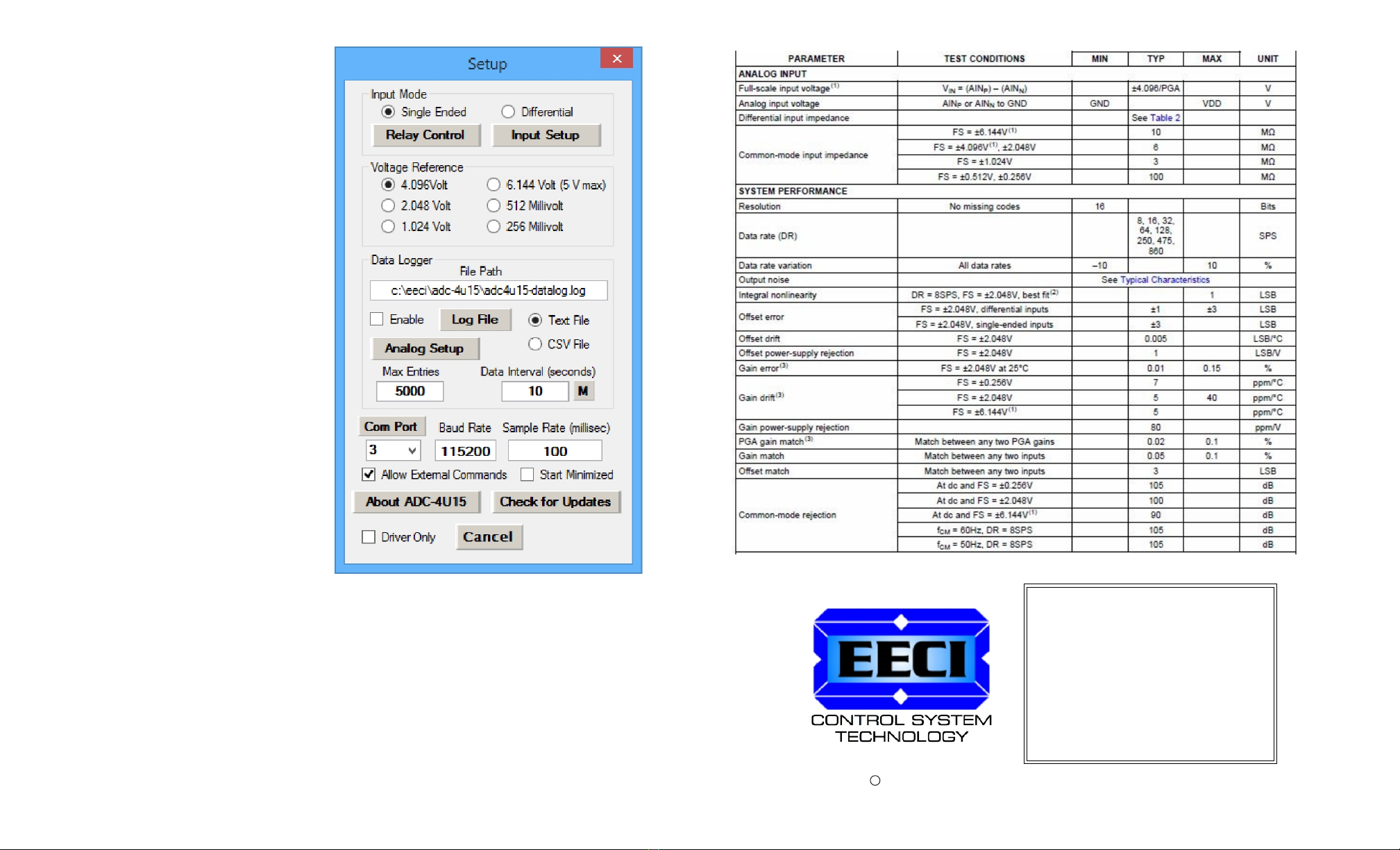
THE ADC-4U15 USER INTERFACE
The ADC-4U15 User Interface allows you to set all of
the basic operating characteristics of the hardware
and permits the ADC-4U15 to send and receive data
from other Windows applications or programs that you
create. Please see page 12 for the Setup window.
When the device driver is started for the first time you
are prompted for the com port that is to be used with
the ADC-4U15. This com port number is saved in the
settings file "adc4U15-set.ini" which is created in the
folder c:\eeci\adc-4U15. The interface will then start
using the com port assigned. The com port indicator
should have a "COM Open" message as shown to the
left with the correct com port shown. The com port
may be changed by clicking the Setup button and
changing the com number in the Com Port window
and then clicking Apply. Available com ports are
updated by clicking the "Com Port" button under
Setup.
Clicking the Setup button allows you to label the
analog inputs for each of the 4 channels. The com
port, baud rate and sampling rate settings are
changed below. Checking the box for differential input
will allow differential inputs to be connected to the
terminal block on the ADC-4U15 (display will change
to two channel mode). The boxes for reference input allow you to set the desired voltage input range. Un-checking
the Allow External Commands box will prevent other Windows applications from sending or receiving data from the
ADC-4U15. The data logger may be enabled by checking the box in the data logger section and entering the desired
time interval and file type information. See page 12 for additional information.
The ADC-4U15 User Interface may be started in driver only mode by checking the Start Minimized box under Setup.
Any changes made to Setup will not take effect until you click the Apply button. Clicking the Apply button saves the
new settings to the adc4U15-set.ini file so that if the device driver is unloaded, it will restart with all the new settings.
Click the Tray button (driver only mode) to close the window after the ADC-4U15 User Interface is set-up for your
application. A blue 4 icon will appear in your system tray (click to re-open the user interface). The ADC-4U15 User
Interface may be left open when used as a stand alone data logger or if an external application is not used. The ADC-
4U15 User Interface may be completely shut down (and driver unloaded) by clicking "Unload Device Driver" at the
bottom of the user interface. Once shut down, you will need to double click the ADC-4U15 desktop icon to re-start the
ADC-4U15 device driver (or clicking the ADC-4U15 icon under All Programs in the EECI folder).The Help button will
provide additional assistance if you installed the Tech Reference from the ADC-4U15 installation CD.
AUTO START-UP FOR THE ADC-4U15 DEVICE DRIVER
By default, the ADC-4U15 device driver is only loaded on demand to conserve system resources. You may install the
ADC-4U15 device driver permanently by checking the "Driver Only" check box under Setup in the ADC-4U15 User
Interface. You will then always see the ADC-4U15 system icon in your system tray* along with the other system
devices (such as your speaker, printer or display adapter). Click the blue 4 icon in your system tray to open the
ADC-4U15 User Interface. If the ADC-4U15 device driver is not installed permanently, you will need to double click
the ADC-4U15 desktop icon to load the ADC-4U15 device driver each time your system starts.
Page 6
VOLTAGE REFERENCE INPUT
The ADC-4U15 allows for several different reference voltage configurations. The reference voltage determines the
voltage input range for all (4) analog input channels or (2) channels in differential mode. The following configurations
are selectable from the ADC-4U15 Setup. Option 1 is the default setting (this allows exactly 8 increments per mv).
Option 1: 4.096 volt - allows a (0 to 4.1) volt input range ((4) channel single ended) (= 0 to 4,096mv)
allows a (-4.1 to +4.1) volt input range ((2) channel fully differential) - 8 increments per mv
Option 2: 5 volt - allows a (0 to 5 volt)* input range or (-5 to +5) in differential mode (= 0 to 6,144mv)
(4) channel single ended or (2) channel fully differential - 5.3333 increments per mv
Option 3: 2.048 volt - allows a (0 to 2) volt input range or (-2 to +2) in differential mode (= 0 to 2,048mv)
(4) channel single ended or (2) channel fully differential - 16 increments per mv
Option 4: 1.024 volt - allows a (0 to 1) volt input range or (-1 to +1) volts in differential mode (= 0 to 1,024mv)
(4) channel single ended or (2) channel fully differential - 32 increments per mv
Option 5: .512 volt - allows a (0 to .5) volt input range or (-.5 to +.5) volts in differential mode (= 0 to 512mv)
(4) channel single ended or (2) channel fully differential - 64 increments per mv
Option 6: .256 volt - allows a (0 to .25) volt input range or (-.25 to +.25) volts in differential mode (= 0 to 256mv)
(4) channel single ended or (2) channel fully differential - 128 increments per mv
*the 0 to 5 volt option is based on a 0 to 6.144 volt range with only the 0 to 5 volt portion usable (see page 12).
SINGLE ENDED ANALOG VOLTAGE INPUTS
Voltages up to hundreds of volts may be divided down to the 5 volt range by using a simple resistance divider as
shown on the following page (the signal source must be capable of driving a 1 ma load). To determine the value
transmitted by the ADC for a specific voltage applied to the divider circuit use the following formula: (VI divided by
DF) times 51 = TV (where TV = transmitted value sent by the ADC, VI = voltage input to divider, DF = divider factor)
DF = full scale voltage divided by 5 volts. EXAMPLE: 100 volts full scale divided by 5 = 20 = DF. A 60 volt input to the
divider divided by 20 multiplied by 51 = 153 = TV, the value transmitted by the ADC (8 bit).
The voltage input source may be located up to several hundred feet from the ADC. The wire which connects the ADC
to the signal source should be a twisted pair to reduce possible input noise (22 or 24 gauge communication cable or
CAT5 typical). Shielded cable may be used to further protect against EMI or lightning noise (the shield should be left
disconnected at the source and connected to an earth ground/equipment ground at the ADC).
Lower millivolt signal levels (such as the output signals from a watt transducer, pressure transducer, load cell, etc.)
with typical full scale voltages of only 20 to 100 millivolts will require the addition of the VA-1, VA-2, VA-4 or VA-8
instrumentation amplifier. The VA-1 connects to any of the analog inputs and will convert a millivolt signal input to a 0
to 5 volt output for input into the ADC. Signal levels this low will may require shielded cable to reduce noise. An
adjustment on the VA-1 will set the input scale. The shield should be left disconnected at the source and grounded to
an earth ground at the VA-1. Applications requiring isolated analog inputs require the VI-8I linear opto isolated
amplifier.
NOTE: When the analog inputs are left floating, (no connection) the ADC will transmit fluctuating numbers as a
result of noise present at the inputs. We recommend that any unused inputs be connected to GND (reference (-)) to
prevent possible errors on other channels (differential inputs should have both inputs shorted together).
FILTERING INPUT NOISE: A .1 uf filter capacitor is installed on the ADC card (one for each channel) which
significantly reduces errors and fluctuation as a result of input noise. A 2.7 mf or 10 mf tantalum capacitor may added
for additional filtering (input response time will be slower).
Shown on the following pages in figures A, B & C are methods for reading contact closure, potentiometer movement
& light levels.
Page 8
INPUT SCALING AND OFFSETS
Analog inputs may be scaled and offsets added by opening the user interface and clicking Setup and then Analog
Setup. This allows you to directly display temperature, pressure, position, etc. by adjusting the raw analog data
coming from the sensor to the actual units (such as degrees, PSI, mm, GPM, RPM, etc,). The Precision setting allows
the units to be displayed in integer, tenth, hundreds, etc. Use the Suffix box to change the display from the default
Units to the required specifier. You may check the "Raw" checkbox to disable all formatting.
DIFFERENTIAL ANALOG INPUTS
The ADC-4U15 may be set to accept (2) fully differential inputs in place of the (4) single ended inputs. The differential
voltage input range is determined by the reference setting as shown on the previous page. The differential input signal
connects to terminals 1 and 2 for differential channel 1 and terminals 3 and 4 for differential channel 2. The GND
terminal connections are not used.
CONNECTION OF LOW LEVEL DIFFERENTIAL SIGNALS TO THE VA-1: If low level differential inputs are
required, the VA-1 may be used to convert a differential signal into a 0 to 5 volt signal for connection to the ADC. The
VA series amplifiers have a reference input (for connection to the ADC reference) which is used to generate a 2.5 volt
offset (adjustable). The gain adjustment on the VA series amplifiers may be adjusted to allow for differential signals as
low as (+) and (-) 5 millivolts or as high as (+) and (-) 5 volts. Using the VA-1 will allow the use of all 4 single ended
inputs on the ADC-4U15 since the low level differential input to the VA-1 is converted to a single ended signal for
connection to the ADC-4U15.
Page 9
USB
1
2
3
4
Differential Analog Terminal
Block Connections
differential input #1 + (Terminal 1)
differential input #1 -(Terminal 2)
differential input #2 + (Terminal 3)
differential input #2 -(Terminal 4)

HIGH VOLTAGE INTERFACING
CAUTION: When working with high voltages, the potential for fire, explosion, electrocution, eye injury or blindness
and life threatening injuries or death exists. If you are not familiar with the precautions needed when working with
high voltages, do not attempt to connect high voltage up to these circuits. To prevent the danger of a high voltage
feeding back to the ADC and the fire/injury/electrocution hazard caused by an open or short circuit, 10 volt 2 watt
zener diodes and a 1/4 amp fuse should be connected as shown in figure E. Wire used to interconnect a high voltage
input must be rated for use with the higher voltage. When connecting the ADC to high voltage AC equipment the
method shown in figure D above is recommended.
The following method is used to divide a high voltage down to the 5 volt range needed for input into the ADC. This
method involves the use of two resistors (R1 and R2) which together add up to Rt (total resistance). The total
resistance is determined by using the Ohms Law to compute the resistance needed for a 1 milliamp current flow
through the resistors. EXAMPLE: If your full scale voltage is 100 volts (R = E divided by I) 100 volts divided by .001
amp = 100,000 ohms (100K ohm). To determine the proper ratio, divide 5 volts by the full scale voltage. 5 divided by
100 volts = .05. Multiple this ratio by the total resistance to determine the value of R2. R1 is then equal to the
difference between the total resistance and R2. EXAMPLE: ratio .05 times total resistance 100,000 ohms = 5,000
ohms (the value of R2). Total resistance 100,000 ohms less R2 5,000 ohms = 95,000 ohms (the value of R1). To
determine the power rating needed for the resistor, use the following formula: P = I squared times R. EXAMPLE: .001
squared = .000001 times R1 95,000 ohms = .095 watts. A 1/8 or 1/4 watt resistor would be sufficient.
Page 10
Fuse or Limiting Resistor (330 ohm 1 watt)
1 Amp Diode (50 volt)
AC Primary Voltage
120, 277, 480 etc.
(-)
6 or 12 Volt
Secondary
100 mf
35 volt
24 ga Communication Cable
To Analog
Input
To Analog
Input
(+)
(-)
1/4 Amp Fuse
Diode
(if AC)
(+)
High Voltage
AC/D C Input
(-)
Ground for
Safety
R1
R2
(1 ma maximum current
through resistors)
(+)
R1
R2
100 mf
35 volt
(if AC)
+
FIGURE C
FIGURE D
Switch or Relay
Contacts etc.
(Reference +)
To Analog Input
(+)
10 K ohm
(Reference -/Analog Ground)
DIGITAL INPUT
(0=OFF)
(255=ON)
FIGURE A
(Reference +)
(Reference -/Analog Ground)
To Analog
Input
POTENTIOMETER
MOVEMENT SENSING
FIGURE B
Ref (-)/Analog Ground
To Analog Input
Ref (+)
27K Ohm
Cadmium Sulfide
Photo Cell
+
10 mf Tantalum Capacitor
USING AN ANALOG INPUT
FOR ON/OFF STATUS MEASURING LIGHT LEVELS
FIGURE E
10K OHM
TYPICAL
IMPORTANT: The full scale voltage used should be the highest possible voltage that could be present at the high
voltage input.
AC voltages may be applied to the high voltage input if a diode is connected in series and a filter capacitor (100 mf,
35 volt typical) is connected between the ADC analog input and the ADC reference (-). AC voltages over 24 volts or
great enough to create an electrical shock hazard or fire should be connected to the ADC analog input using a step-
down transformer to reduce the high voltage down to the 5 volt range as shown in figure D. A diode and filter
capacitor must be connected on the secondary side of the transformer (a common low current power transformer
may be used).
VOLTAGE INPUT AMPLIFICATION AND SIGNAL CONDITIONING
The ADC-4U15 defaults to a 0 to 4 volt input range (setup allows input ranges as low as 0 to .25 volts). When the
input voltage range is required to be lower, (such as with a watt transducer or load cell) an external instrumentation
amplifier must be used to amplify the input signal to the 0 to 4 volt input range of the ADC.
Several general purpose instrumentation amplifiers are available to amplify lower signal levels to the 0 to 4 volt range
required by the ADC (for use with 8, 10 and 12 bit inputs). The VA-1 is a single channel amplifier for connection to
the ADC-4U15, ADC-8U or ADC-12U. The VA-2, VA-4 and VA-8 amplifiers are two, four and eight channel versions of
the VA-1. The VA-1, VA-2, VA-4 and VA-8 all provide 15 turn potentiometer(s) for gain adjustment (amplification
level). The amplification level is adjusted for a 0 to 100 millivolt input at the factory. The amplification level may
adjusted for signal inputs as low as 0 to 5 millivolts or as high as 0 to 5 volts. Lower signal levels (such as the output
signal from a watt transducer, pressure transducer, load cell, etc.) with typical full scale voltages of only 20 to 100
millivolts will require the addition of the VA-1 instrumentation amplifier when connecting to the ADC. Signal levels this
low may require shielded twisted pair wire. The shield should be left disconnected at the source and grounded to an
earth electrical ground at the VA-1.
CONNECTING SENSORS TO THE ADC-4U15
A large variety of sensors, transducers, load cells and other devices that provide an analog output may be connected
to the ADC-4U15. Most types of sensors may be located up to 1,000 feet from the ADC-4U15. Pull up resistors may
be installed on the underside of the ADC-4U15 for 2 wire sensors that receive power from the USB port. The cable
used to connect sensors to the ADC-4U15 should be twisted pair or shielded twisted pair to suppress environmental
noise. Low cost CAT 5 cable works well when multiple sensors are in the same location.
MOUNTING
The ADC-4U15 Analog to Digital card may be mounted in an enclosure (part # EN-C or EN-D) or on a metal mounting
panel using the MT-1 stand-off mounting hardware as shown below. The ADC-4U15 will attach to the 4 stand-off
spacers using 4-40 machine screws (4 mounting holes are provided on the ADC-4U15). Contact technical support for
more information on mounting panels and various mounting layouts.
Page 11
ADC-4U15
+
-
+
-
Twisted Pair
Pressure
Transducer
Power
-
+
ADC-4U15
+
-
+
-
Twisted Pair
2 wire
temperature
sensor
ADC-4U15
SIDE
VIEW
1/2" Stand-Off
1/4" 4-40 Machine Bolt
1/4" 4-40 Machine Bolt
MP-C
Mounting Panel
with MT-1
Stand-Off Kit
10 Volt 5 Watt
Zener Diodes
The additional safety components
are not needed at lower safe levels
(such as 24 volts or less)
RAW ANALOG DATA
The ADC-4U15 will present the raw analog data as a
number between 0 and 32767* when in 15 bit single
ended mode and a number between -32768 and
+32767* when in 16 bit differential mode.
*the usable range with the ADC-4U15 reference
voltage set to 6.144 will be 0 to 26665 in 15 bit single
ended mode and -26666 to +26665 in differential mode
since the portion of the ranges from (5 volts to 6.144)
and from (-6.144 to -5 volts) are not usable.
HIGH PRECISION INSTRUMENT AMP
The built-in high precision instrument amplifier utilizes
6 predefined precision voltage references that have
been selected to provide an exact voltage
measurement per increment as follows:
256 mv .0078125 mv increments (128 per mv)
512 mv .015625 mv increments (64 per mv)
1.024 v .03125 mv increments (32 per mv)
2.048 v .0625 mv increments (16 per mv)
4.096 v .125 mv increments (8 per mv)
6.144 v .1875 mv increments (16 per 3 mv)
DIFFERENTIAL INPUT IMPEDANCE
at 6.144 volts: 22 Meg ohm
at 4.096 volts: 15 Meg ohm
at 2.048 volts: 4.9 Meg ohm
at 1.024 volts: 2.4 Meg ohm
at 512 mv: 710 Kilo ohm
at 256 mv: 710 Kilo ohm
NOTE: Once a change is made, the Apply Button will
appear. Changes will not be applied until you click the
Apply button. The changes are saved to the
ADC-4U15.ini file.
Relay and Input labels may be changed by clicking the Relay Control or Input Setup buttons. Click the Analog Setup
button to make changes to the analog labels, suffix, scale, offset or precision. These also apply to logged data.
The voltage input range may be set by selecting 1 of the 6 possible gain levels using the built in instrument amp.
Start the data logger by checking the Enable box. The logger will roll-over or stop based on the setting in the Max
Entries box. The Data Interval may be set to minutes or seconds and will log the data based on the setting in the box.
Click the Com Port button to refresh the available Com Ports. Enter or use the pull-down arrow to set the Com Port.
The Sample Rate is the interval between samples (in the example above, the setting is 100 milliseconds or 10
samples per second).
Check the Start Minimized box to start the ADC-4U15 device driver in "driver only" mode. Blue 4 icon will show in
your system tray.
Page 12
ELECTRONIC ENERGY CONTROL, INC.
14960 Maple Ridge Rd
Milford Center OH 43045-9016
USA
(937) 349-6000
(800) 842-7714
(937) 349-6000
http://www.eeci.com
PHONE*.................
ORDERS................
TECH SUPPORT...
E-mail*....................
Web*........................
*International & Domestic
Copyright 2014 - 2022 Electronic Energy Control, Inc. All Rights Reserved
c
®
Table of contents
Other EECI Media Converter manuals


Popular Media Converter manuals by other brands


Irlbacher Eleltronik
Irlbacher Eleltronik Intercom Splitter Assembly instruction

Eurotops
Eurotops 46291 manual

RC Electronics
RC Electronics Finch Jeti manual

PiXORD
PiXORD PMC600 user manual

Omnitron Systems Technology
Omnitron Systems Technology iConverter Gx AN user manual

B+B SmartWorx
B+B SmartWorx 422CEC Quick start guides