EECI CO-485USB Use and care manual

TABLE OF CONTENTS
Specifications, Description and Technical Support..... page 1
Connection Diagram................................................... page 2
Set-Up & Testing......................................................... page 3 & 4
Power Supply Shunts................................................. page 5
Trouble-Shooting......................................................... page 5
Connecting to the AR-16 Relay Interface.................... page 6 & 8
Connecting to the ADC-4, ADC-16 and STA-16.......... page 7
Warranty...................................................................... page 9
SPECIFICATIONS
Power Supply....................... Selectable
(Option1) 5VDC (powered from USB port)
(Option2) 6 to 24VDC wall adapter (provides isolation)
(Option3) 5VDC external supply (provides isolation)
Channels.............................. 1 channel, Full Duplex, 4 wire (2 twisted pairs)
Expansion Capability............ EX-8M Expansion card (adds 8 relays, 8 inputs or combinations)
(requires Windows XP service pack 3 up to Windows 8.1 versions)
Computer Interface.............. USB only (Windows ME, 2000, Server 2003 or later (32 and 64 bit versions)
includes Vista, Windows 7, Windows 8.1, Windows 10 and Windows Server
Weight................................. 1.5 ounces
Size...................................... 2.375 inches by 3.1 inches
DESCRIPTION
The CO-485USB connects to any available USB port on a Windows computer or laptop and converts signal levels to
the RS-485 standard. The CO-485USB operates in full duplex mode (4 wire, 2 twisted pairs), transmitting and
receiving at the same time.
24 HOUR TECHNICAL SUPPORT
Technical support for our products is available by calling (349) 349-6000. If a technical adviser is not available, please
leave your name, phone number and a time that you can be reached. Your call will be returned as soon as possible
and within 8 hours. Calls received during normal business hours are usually returned within minutes.
Page 1
TECHNICAL REFERENCE
Click for more info: www.eeci.com/co-485usbp.htm
CO-485USB
USB to RS-485
CONVERTER
(937) 349-6000
(800) 842-7714
(937) 349-6000
PHONE...................
ORDERS................
TECH SUPPORT...
E-mail.....................
www.eeci.com
SET-UP AND TESTING
Upon receiving your CO-485USB, you should connect and test the operation of the hardware to verify proper operation.
Please set-up and test the CO-485USB as follows (Windows XP*, Vista, Windows Server 2008, 2012, Windows 7, 8 or
later required for EX-8M expansion) *service pack 3
(1) Connect your CO-485USB to your computer USB port using a CC-USBB cable (1 to 10 foot). A high percentage of
systems will already have a USB Com driver installed and this is indicated by a pop up balloon in the lower right side of
your screen. The balloon message may automatically assign a com port to your CO-485USB and the com port
assigned will be shown. If this occurs then make note of the com port for step 4 and go to step 2.
The balloon message may also indicate that a driver has been located on your system and is being installed and after
which a com port is assigned to the CO-485USB. If this occurs then make note of the com port for step 4 and proceed
to step 2.
The balloon message may request to search Windows Update for the correct driver. If you are connected to the
Internet, you may click yes and allow the USB com driver to be installed and after which a com port is assigned to the
CO-485USB. If this occurs, then make note of the com port for step 4 and go to step 2.
If you are using Windows XP, the "Found New Hardware Wizard" may pop up. If you have an Internet connection, allow
the wizard to connect to Windows Update and install the USB com driver, then go to step 2.
If none of the above actions occur or if an error message is shown, you may install the USB Com driver* from the
supplied CD by clicking the "Install USB Com Driver" button in the CD start window. After the USB com driver is
installed, disconnect your CO-485USB from the USB port, wait 5 seconds and plug back in. You may see a balloon
message with the com port assigned to the CO-485USB (if not, you will find the com port assigned in step 2).
*before installing a new USB com driver, go to Control Panel/Device Manager/Ports to check if a Prolific driver is shown
(expand the category by clicking on the + or arrow). If you see a "Prolific USB to Serial Comm Port (COM-)" entry, the
number to the right of COM is your com port. Right click on the entry, then properties, then the driver tab to check the
version. If you have an out of date version and an Internet connection, click the "Update Driver" button to install the
updated driver. Please note that it may be necessary to remove the outdated Prolific Com driver before the updated
driver will correctly install (the supplied CD driver installation feature has a remove option - click Install Com Driver).
(2) Check your USB Com driver by going to Control Panel/Device Manager/Ports (see detail on the next page for your
Windows version) or click the "Open Control Panel" button on the supplied CD startup window. Click the small triangle
(or +) to the left of Ports to expand the Ports category, right click the Prolific USB to Serial Comm Port, click properties
and open the driver tab. Your USB Com driver must be Prolific version 3.4.62.293 or higher (dated 10/17/2013 or later).
If your USB Com driver is up to date then please note the Com port number assigned and jump to step 3.
If your USB Com driver is not up to date, click the "Update Driver" button (under driver tab). If the driver does not
update, disconnect the CO-485USB USB cable from your computer and install the updated USB Com driver (located
on your CO-485USB CD from the startup window, in the USB Com driver folder or from Windows Update). Please see
detail*
Page 3
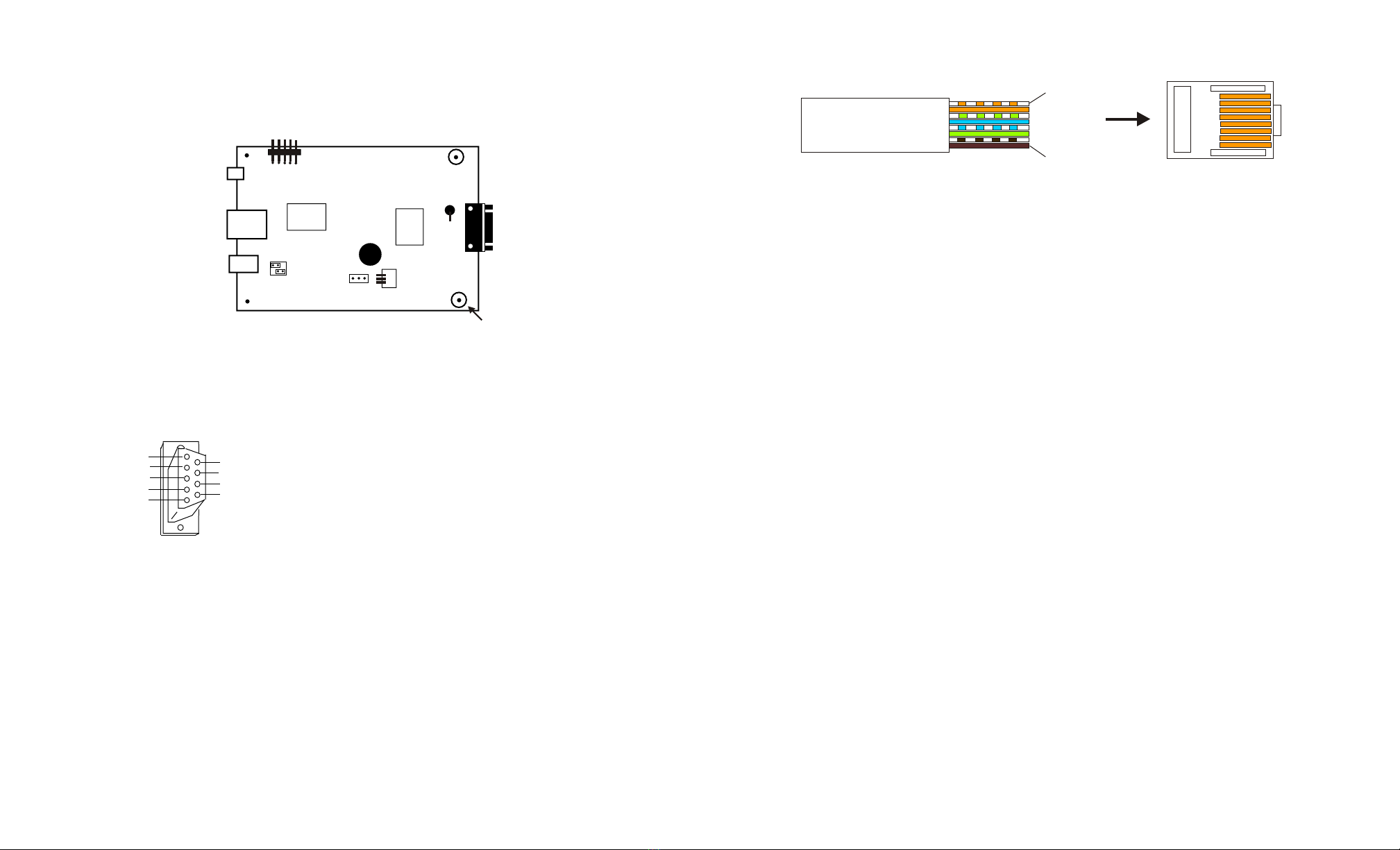
CONNECTION DIAGRAM
CO-485USB
USB to RS-485 Converter
* grounds cable shield and TransZorbs
IMPORTANT: Always discharge any static electricity from your body by touching the bare metal on the back of your
computer before handling your CO-485USB or attached hardware.
RS-485 DB-9 CONNECTOR PIN OUT
RS-485 RJ-45 PIN OUT
(EIA/TIA -568-B standard)
(1) WHT-ORG (R-) connect to (T-) on ADC-16 or STA-16
(2) ORG (R+) connect to (T+) on ADC-16 or STA-16
(3) WHT-GRN not used
(4) BLU (T+) connect to (R+) on AR-16, ADC-16 or STA-16
(5) WHT-BLU (T-) connect to (R-) on AR-16, ADC-16 or STA-16
(6) GRN not used
(7) WHI-BRN not used
(8) BRN not used
If the CO-485USB was ordered with a shielded RJ-45, the Equipment Ground/ Shield connection is the RJ-45 case.
Page 2
RS-485
DB-9 socket
or RJ-45
USB
EXT Power
EXT Power
Select
USB Power
Type B USB
to computer
Aux. Out (+)
Transmitter (+)
Equipment Ground
Receiver (+)
Aux. In (+)
Aux. Out (-)
Transmitter (-)
Receiver (-)
Aux. In (-)
(1)
(2)
(3)
(4)
(5)
(6)
(7)
(8)
(9)
PLUG
REAR VIEW
(solder side)
DB-9 PIN
(1)
(2)
(3)
(4)
(5)
(6)
(7)
(8)
(9)
CONNECT TO
Not used
(Red of Red/Black pair), to R+ *
Connect to shield *
(White of White/Black pair), to T+ *
Not used
Not used
(Black of Red/Black pair), to R- *
(Black of White/Black pair), to T- *
Not used
*Belden 9302 instrumentation cable recommended
(2 pair twisted with shield 22awg)
CAT 5 cable
WHT-ORG
ORG
WHT-GRN
BLU
WHI-BLU
GRN
WHI-BRN
BRN
RJ-45 Plug
(key tab latch underneath)
Latch
Pin 1
Pin 8
Expansion
Header
5V
Power LED
EOL
Resistor
Ground Lug*
Ground Lug*

POWER SUPPLY OPTIONS
(Option1) 5VDC (powered from USB port).... set shunts as shown
(Option2) 6 to 24VDC wall adapter (provides isolation).... disconnect or set shunts as shown
(this option regulates the power to the CO-485USB at 5 volts using the on board 7805 regulator)
(Option3) 5VDC external supply (provides isolation).... disconnect or set shunts as shown
IMPORTANT: when using external power, the USB power shunts must be completely disconnected.
When using USB power, the EXT power shunts must be completely disconnected.
Using external power is recommended so that your computer and USB port are completely electrically isolated from
the RS-485 lines. Opto isolators on the CO-485USB provide the isolation by using a light beam and a photo
transistor to electrically disconnect your USB port from the RS-485 lines when you use an external power source.
Electrically isolating the computer and USB port from the RS-485 lines is strongly recommended for all commercial
use of the CO-485USB.
TROUBLE-SHOOTING THE CO-485USB
(1) Verify that your USB com driver is installed by going to Device Manager and checking for the Prolific USB to
Serial Comm Port entry. Right click on the entry, then Properties, select the Driver tab and verify that the driver is
dated 8/15/2014 or later. If the driver is out of date, connect to the Internet and click the Update Driver button. Please
note that an out of date driver may allow the CO-485USB to partially function and/or with erratic operation.
(2) Verify that the Prolific USB to Serial Comm Port entry is the com port used by your CO-485USB. You may do this
by watching the entry in Device Manager and unplugging your CO-485USB from your computer USB port. The entry
should disappear and then re-appear when you plug the CO-485USB back in to your computer USB port.
(3) Try replacing the USB cable and/or using a different USB port. Reset your USB com in your software. Hardware is
reset by unplugging from the USB port, waiting 30 seconds and then plugging the USB cable back in.
The RS-485 driver may be referred to as Transmitter or T+ or T-.
The RS-485 receiver may be referred to as R+ and R-.
IMPORTANT CAUTION: The RS-485 signal standard is very forgiving of incorrect wire connections.
The ADC-16 or STA-16 may appear to operate normally for a period of time (ranging from several hours to several
months) even with incorrect polarity of the receiver/driver pairs or crossed wires (such as driver to driver or receiver
to receiver or other combinations). DOUBLE CHECK ALL WIRE CONNECTIONS OF THE TWISTED PAIRS. The
computer RS-485 driver (+) must connect to the ADC-16 receiver (+). The computer RS-485 driver (-) must connect
to the ADC-16 receiver (-). The ADC-16 driver (+) must connect to the computer receiver (+) and the ADC-16 driver (-
) must connect to the computer receiver (-). All end of line resistors must be in place (100 ohm resister is installed on
the ADC-16 or STA-16 at the factory). Failure to correctly connect the receiver/driver pairs and/or failure to correctly
install the end of line resistor(s) will result in data errors and/or failure of the RS-485 receiver/driver ICs.
*Peel back cable at least 10" to verify twisting of cable pairs when using Beldon 9302 cable. The two black
conductors can become cross paired which can not be detected by a continuity test. Cross paired wiring will cause
intermittent data errors.
Page 5
HOW TO OPEN DEVICE MANAGER
Windows XP, VISTA or Windows 7
Click the Start Button (lower left of screen), then Control Panel (right side). With the view set to classic view, small or
large icons, click (or double click) the Device Manager icon. With Windows XP you will need to click the System icon
(in Control Panel) then the Hardware Tab then the Device Manager button. You may also use the supplied CD to open
Device Manager by clicking the "Open Device Manager" button when the CD auto starts.
HOW TO OPEN DEVICE MANAGER
Windows 8, 8.1 and Windows Server 2012
Move your mouse cursor to the lower right side of your screen and click on Settings. Click on Control Panel near the
top and dlick on the Device Manager icon.
Page 4
USB Power EXT Power
Select
USB Power
EXT Power
Select
USB Power
EXT Power
Select
5V
5V
EXT
Disconnect
Disconnect

Page 7
NOTE: The use of shielding on the RS-485 interconnect cable is strongly recommended to protect the
RS-485 receiver/driver ICs from damage which may be caused by electrical storm and lightning
transients. The shield of the cable should be connected to an earth ground or an equipment ground
(connected to your electric system ground via the third prong on the electric cord or connected to a ground rod).
RS-485 END OF LINE RESISTOR: the end of line resistor which is installed on the AR-16 may be in the range of 54
ohms to 120 ohms. The default value for use with a single AR-16 is 100 ohms. If the twisted pair cable run to the AR-
16 is in a high noise electrical environment it is best to use a lower value (but no lower then 54 ohms). The
disadvantage to using a lower value is that the RS-485 receiver/driver ICs will run hotter.
When multiple AR-16 cards are connected to the RS-485 twisted pair, the last AR-16 should have the end of line
resistor installed (clip the end of line resistor on all the other AR-16 cards (see pages 8 and 9).
Page 6
T-T+R-R+ - +
TERMINAL BLOCK CONNECTIONS
RS-485 Transmitter (-) (connect to black of white/black pair)
RS-485 Transmitter (+) (connect to white wire)
RS-485 Receiver (-) (connect to black of red/black pair)
RS-485 Receiver(+) (connect to red wire)
Power supply input (use caution, reversed polarity may cause
Power supply input damage, 9 to 14 volts DC only)
(T-)
(T+)
(R-)
(R+)
(-)
(+)
RS-485 TERMINAL CONNECTIONS
ADC-4
ADC-8
ADC-16
STA-8
OR
STA-16
NOTE: RECEIVER/TRANSMITTER PAIRS SHOULD BE TWISTED
RED WIRE
(RS-485 +)
BLACK WIRE
(RS-485 -)
R+
R-
RS-485 OUTPUT
FROM COMPUTER
TWISTED PAIR WIRE
(up to 4,000 feet)
WHITE WIRE
(RS-485 +)
BLACK WIRE
(RS-485 -)
T+
T-
RS-485 INPUT
TO COMPUTER
TWISTED PAIR WIRE
(up to 4,000 feet)
- + - +
T-T+ R-R+
RS-485
DRIVER RS-485
RECEIVER
100 OHM END OF
LINE RESISTOR
NOTE: On cards equipped with a
resetting fuse, the fuse is the yellow
disc located near the terminal block.
When the fuse is tripped due to a
short or overload, the fuse may be
reset by correcting the short and
removing power for about a minute
(or the fuse will reset automatically
after the fuse cools). The Transzorb
is the black cylinder shaped part
located above the terminal block.
Use Belden # 9302
communication cable*
or shielded CAT 5
(CAT5 - Blue of pair 1)
(CAT5 - White of pair 1)
(CAT5 - White of pair 2) (CAT5 - Orange of pair 2)
LOCAL COMPUTER
RS-485
TRANSMITTER
(R-)
(R+)
1 R
AR-16
100 OHM
RESISTOR
NOTE: USE TWISTED PAIR WIRE FOR
INTERCONNECT (or twisted pair with shield)
CABLE RUN MUST BE 4,000 FEET OR LESS
(Use 1P-22GS twisted pair sensor cable with shield)
(T+)
(T-)
Important: Observe Polarity
RED WIRE
BLACK WIRE
RS-485 TERMINAL CONNECTIONS
for a single AR-16
(T+)
(T-)
NOTE: The use of shielding on the RS-485 interconnect cable is strongly recommended to protect the
RS-485 receiver/driver ICs from damage which may be caused by electrical storm and lightning
transients. The shield of the cable should be connected to an earth ground or an equipment ground
(connected to your electric system ground via the third prong on the electric cord or ground rod).
IMPORTANT CAUTION: The RS-485 signal standard is very forgiving of incorrect wire connections.
The ADC-16 may appear to operate normally for a period of time (ranging from several hours to several
months) even with incorrect polarity of the receiver/driver pairs or crossed wires (such as driver to driver
or receiver to receiver or other combinations). DOUBLE CHECK ALL WIRE CONNECTIONS OF THE
TWISTED PAIRS. The computer RS-485 driver (+) must connect to the ADC-16 receiver (+). The
computer RS-485 driver (-) must connect to the ADC-16 receiver (-). The ADC-16 driver (+) must
connect to the computer receiver (+) and the ADC-16 driver (-) must connect to the computer receiver (-).
All end of line resistors must be in place (120 ohm resister is installed on the ADC-16 or STA-16 at the
factory - see above). Failure to correctly connect the receiver/driver pairs and/or failure to correctly
install the end of line resistors will result in data errors and/or failure of the RS-485 receiver/driver ICs.
*Peel back cable at least 10" to verify twisting of cable pairs on Beldon 9302 cable. The two black conductors can
become cross paired which can not be detected by a continuity test. Cross paired wiring will cause intermittent data
errors.
RS-485 END OF LINE RESISTOR: the end of line resistor which is installed on the AR-16 may be in the range of 54
ohms to 120 ohms. The default value for use with a single AR-16 is 100 ohms. If the twisted pair cable run to the AR-
16 is in a high noise electrical environment it is best to use a lower value (but no lower then 54 ohms). The
disadvantage to using a lower value is that the RS-485 receiver/driver ICs will run hotter.
When multiple AR-16 cards are connected to the RS-485 twisted pair, the last AR-16 should have the end of line
resistor installed (clip the end of line resistor on all the other AR-16 cards (see pages 8 and 9).
When using a split cable run and (2) end of line resistors (see page 8), the total end of line resistance must not be
lower than 54 ohms (use (2) 120 ohm resistors).
NOTE: The AR-16 relay select lines normally default to relays 1 thru 16. When additional AR-16 Relay Interface
cards are placed on the same RS-485 line, the relay select line (pin 19) must be jumpered to control the desired
relays. The line should be cut where the track narrows at the feed thru hole (above pin 19) on the two 24 pin
74LS154 ICs on the top of the card. Pin 19 on each 74LS154 should connect to the desired select line on the lowest
74LS154 (pins 3 thru 17, pin 12 is ground, pins 1 and 2 are default). Each of the upper two 74LS154 ICs control 8
relays.
WARRANTY AND CARE OF THE CO-485USB
The CO-485USB USB to RS-485 Converter is warranted against factory defects for a period of 90 days from the date
of purchase. The CO-485USB has proven to be extremely reliable in actual operation during field tests. We
recommend that the CO-485USB and associated hardware be installed in a suitable enclosure (4 mounting holes are
provided on the circuit board).
Page 9
Page 8
LOCAL COMPUTER
RS-485
TRANSMITTER
(R-)
(R+)
1 R
(R-)
(R+)
(R-)
(R+)
AR-16
AR-16
100
OHM*
AR-16
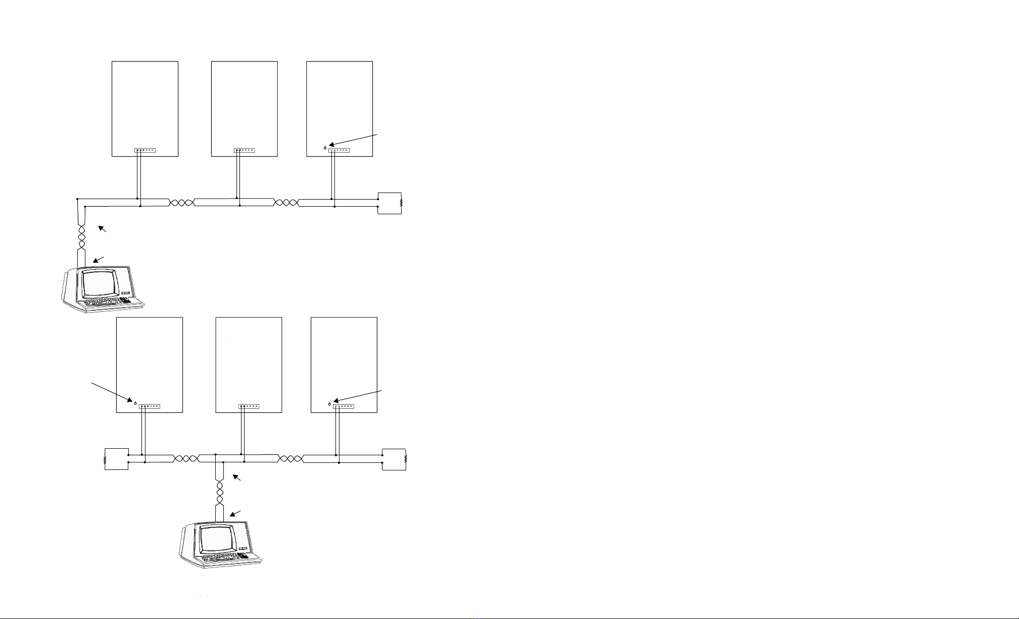
*THIS RESISTOR SHOULD
BE INSTALLED IN THE LAST AR-16
(SHOWN ABOVE)
NO RESISTOR
(cut if present)
END OF LINE
100 OHM Resistor
should be here
NOTE: USE TWISTED PAIR WIRE FOR
INTERCONNECT (or twisted pair with shield)
CABLE RUN MUST BE 4,000 FEET OR LESS
Use 1P-22GS twisted pair sensor cable with shield)
(T+)
(T-)
Important: Observe Polarity
Up to (8) AR-16 Relay Interface
cards may be connected to a
single RS-485 line, providing
control for up to 128 relays.
RED WIRE
BLACK WIRE
RS-485 CONNECTIONS FOR THE AR-16
NO RESISTOR
(cut if present)
LOCAL COMPUTER
RS-485
TRANSMITTER
1 R
AR-16
120
OHM *
120
OHM *
120 OHM
RESISTOR
*THIS RESISTOR SHOULD
BE INSTALLED IN THE LAST AR-16
(SHOWN ABOVE)
*THIS RESISTOR SHOULD
BE INSTALLED IN THE LAST AR-16
(SEE ABOVE)
120 OHM Resistor
should be here
(T+)
(T-)
Important: Observe Polarity
NO RESISTOR
(cut if present)
(R-)
(R+)
(R-)
(R+)
(R-)
(R+)
AR-16
AR-16
Single Pair cable run with single end of line resister
Split cable run with splice
in middle using 2 end of
line resistors

PHONE*.................
ORDERS................
TECH SUPPORT...
E-mail*....................
web*........................
*International & Domestic
(937) 349-6000
(800) 842-7714
(937) 349-6000
https://www.eeci.com
ELECTRONIC ENERGY CONTROL, INC.
14960 Maple Ridge Rd
Milford Center OH 43045-9016
USA
Copyright 2016 - 2021 Electronic Energy Control, Inc. All Rights Reserved
c
®
Other EECI Media Converter manuals


Popular Media Converter manuals by other brands


RGBlink
RGBlink Q4L user manual

MADRIX
MADRIX ORION Technical Manual & Quick Start Guide

Honeywell
Honeywell N568X Integration manual

Omnitron Systems Technology
Omnitron Systems Technology Plug-in Module iConverter 2FXM quick start guide

evertz
evertz 2405OE instruction manual

ADL
ADL GT40 alpha Questions and answers