PAQ
B-232
・All specifications are subject to change without notice.
Example :
PAQ65D48-3325/PV; Represent positive logic, OVP/OCP Auto-restart
MODEL
ITEMS/UNITS CH
PAQ65D48-2518 PAQ65D48-3318 PAQ65D48-3325 PAQ65D48-5033
12121212
Input Voltage Range V 36 - 76 VDC
Efficiency (Typ) (*2) %86.0 87.0 90.0
Current (Typ) (*2) A 0.82 0.97 1.10 1.36
Output
Nominal Voltage VDC 2.5 1.8 3.3 1.8 3.3 2.5 5 3.3
Minimum Current A 0
Maximum Current A 15 17 15 17 15 17 13 16
Maximum Current Combination A Io1+Io2 = 18A
Total Allowable Power (*1) W Po1+Po2 = 37.5 Po1+Po2 = 49.5 Po1+Po2 = 65
Voltage Setting Accuracy (*2) % ± 2
Maximum Line Regulation (*5) mV ±6.6 ±10 ±6.6
Maximum Load Regulation (*6) mV ±16.5 ±25 ±16.5
Temperature Coefficient 0.02%/℃
Maximum Ripple & Noise (*4)
mVp-p
75 100 75 100 75 100
Voltage Adjustable Range (*3) ±10%
Function
Over Current Protection
(Io1+Io2) (*7)(*8)(*10) 105 ~160%
Current limiting with inverter shutdown (Option available : Refer to option table)
Over Voltage Protection (*7)(*8) 120 ~140%
Inverter shutdown (Option available : Refer to option table)
Remote ON/OFF Control (*8) Negative logic (Option available : Refer to option table)
Parallel Operation ------------
Series Operation ------------
Environment
Operating Temperature ℃-40 to +85
Storage Temperature ℃-40 to +100
Operating Humidity %RH 5 ~ 95 (No dewdrop)
Storage Humidity %RH 5 ~ 95 (No dewdrop)
Vibration At no operating, 10 - 55Hz (sweep for 1 min.)
Amplitude 0.825mm constant (maximum 49.0 m/s²) X,Y,Z 1 hour each
Shock 196.1 m/s² (In package)
Cooling (*8)(*9) Convection cooling / forced air cooling with derating
Isolation Withstand Voltage Input - Output : 1.5kVDC for 1 min.
Isolation Resistance More than 100Mohm at 25℃and 70 %RH, Input - Output : 500 VDC
Standards
Safety Standards Approved by UL60950-1, CSA 22.2 No.60950-1, EN60950
Mechanical
Weight (Typ) g 40
Size (W x H x D) mm 36.8 x 8.9 x 57.9 ( Refer to outline drawing)
PAQ65D48 PAQ65D48 Specifications
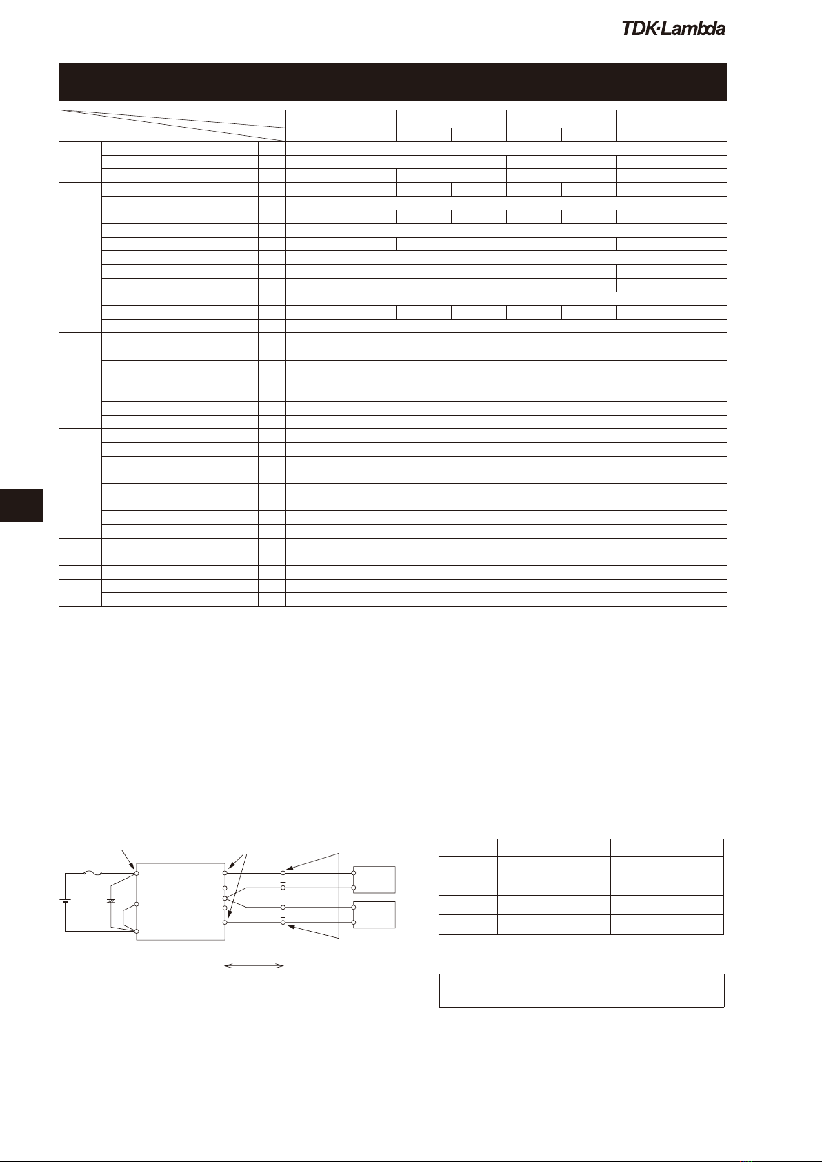
■ Basic Connection ■ Option Table
PAQ65D
(*1) Use external fuse (fast blow type) for each unit.
(*2) Recommended input capacitor C1
-20℃to +85℃: 33µF electrolytic type capacitor.
-40℃to +85℃: 33µF ceramic capacitor or equivalent such
as 5 parallel 6.8µF ceramic type capacitor.
(*3) 22µF ceramic capacitor
Option : ON/OFF Logic OVP/OCP
Standard Negative Shut-down
/P Positive Shut-down
/V Negative
Auto-restart
/PV Positive
Auto-restart
(*1) Maximum allowable combination output power for both channel; also maximum output current for each channel and combination output current for
both channel should not exceeded.
(*2) At 48 VDC, ambient temperature = +25℃and air velocity = 2m/S; 5033: Io1 = Io2 = 7.5A; 3325, 3318, 2518: Io1 = Io2 = 8.5A.
(*3) Additional external components have to be connected; Both outputs are trim independantly; Refer to application notes.
(*4) Measured at Ta = 25℃, Vin = 48VDC and with external components connected;
refer to basical connection drawing. For all temperature range, please refer to the application notes.
(*5) 36 ~ 76 VDC with respect to nominal input line 48V; constant load; ambient temperature = +25℃.
(*6) No load ~ full load with respect to 50% of maximun load; other output: no load; constant input voltage; ambient temperature =+25℃.
(*7) CNT reset or manual reset. Auto-restart option available.
(*8) Refer to application notes.
(*9) Refer to output derating curve.
(*10) Percentage is with respect to maximum combination current which is 18A.
Option for “/C”
(/C, /CP, /CV, /CPV)
Each output voltage can be varied
simultaneously and by the same
proportion by one trimmer.
MeasurementpointforVin
+Vin
Fuse 5A (*1)
C1
(*2)
+
Vin
36〜76VDC
CNT
-Vin
Vo2
Trim2
Gnd
Trim1
Vo1
L=50mm
C3 22uF(*3)
C222uF(*3) +
-
-
+Load
Load
MeasurementpointforVo,
line&loadregulation
Measurementpointforoutputripple&noise
Bandwidthforscope:20MHz