EEG iCap CC1260 User manual

EEG CC1260
iCap™ Interface Card
Product Manual
EEG Enterprises, Inc.
586 Main Street
Farmingdale, New York 11735
TEL: (516) 293-7472 FAX: (516) 293-7417
Copyright © EEG Enterprises, Inc. 2018
All rights reserved.

CC1260 iCap™ Interface Card
Contents
1 Introduction 3
1.1 Product Description . . . . . . . . . . . . . . . . . . . . . . . 3
2 Rear Module 3
3 CC1260 Operation 5
3.1 Front Panel . . . . . . . . . . . . . . . . . . . . . . . . . . . . 5
3.2 DashBoard Menus . . . . . . . . . . . . . . . . . . . . . . . . 5
3.2.1 System . . . . . . . . . . . . . . . . . . . . . . . . . . . 8
3.2.2 Audio . . . . . . . . . . . . . . . . . . . . . . . . . . . . 10
3.3 Web Configuration . . . . . . . . . . . . . . . . . . . . . . . . 12
4 Connecting to Remote Encoders 13
A General-Purpose I/O 14
B Serial Port Connector 15
C Video/Connector Specifications 16
Copyright © EEG Enterprises, Inc. 2018 1

CC1260 iCap™ Interface Card
Copyright 2018, EEG Enterprises, Inc. All rights reserved. The
contents of this manual may not be transmitted or reproduced in
any form without the written permission of EEG.
The revision date for this manual is June 5, 2018.
2 Copyright © EEG Enterprises, Inc. 2018

CC1260 iCap™ Interface Card
1 Introduction
1.1 Product Description
The CC1260 iCap™ Interface Card provides access to EEG’s iCap™ net-
work for legacy caption encoders. The CC1260 works just like any other
iCap™ encoder from a captioner’s point of view, but it outputs caption
data via TCP/IP and RS-232 to non-iCap™ encoders, rather than directly
encoding closed captions into SDI.
2 Rear Module
3

CC1260 iCap™ Interface Card
MASTER IN Master video input. Accepts SMPTE 259M
SD–SDI, SMPTE 292M HD–SDI, or SMPTE
424M 3G–Level-A SDI.
AUX IN Reserved.
MASTER OUT Reserved.
AUX OUT Reserved.
GP IN A and GP IN B Two Molex 87831-0841 connectors, each
containing 4 GPI inputs. See Appendix A for
more information regarding GPIO usage.
GP OUT Molex 87831-0841 connector containing 4
GPI outputs. See Appendix A for more in-
formation regarding GPIO usage.
SERIAL Connector for cable containing two DB–9
(RS-232) serial ports labeled P1 and P2.
P2 will output all caption data entered via
iCap™.
LAN 1000-Base Ethernet port for connection to
LAN. After configuring your CC1260’s net-
work settings in DashBoard (see below),
you can view the Web Configuration site for
your card by navigating to its local IP ad-
dress in your web browser.
4
CC1260 iCap™ Interface Card
3 CC1260 Operation
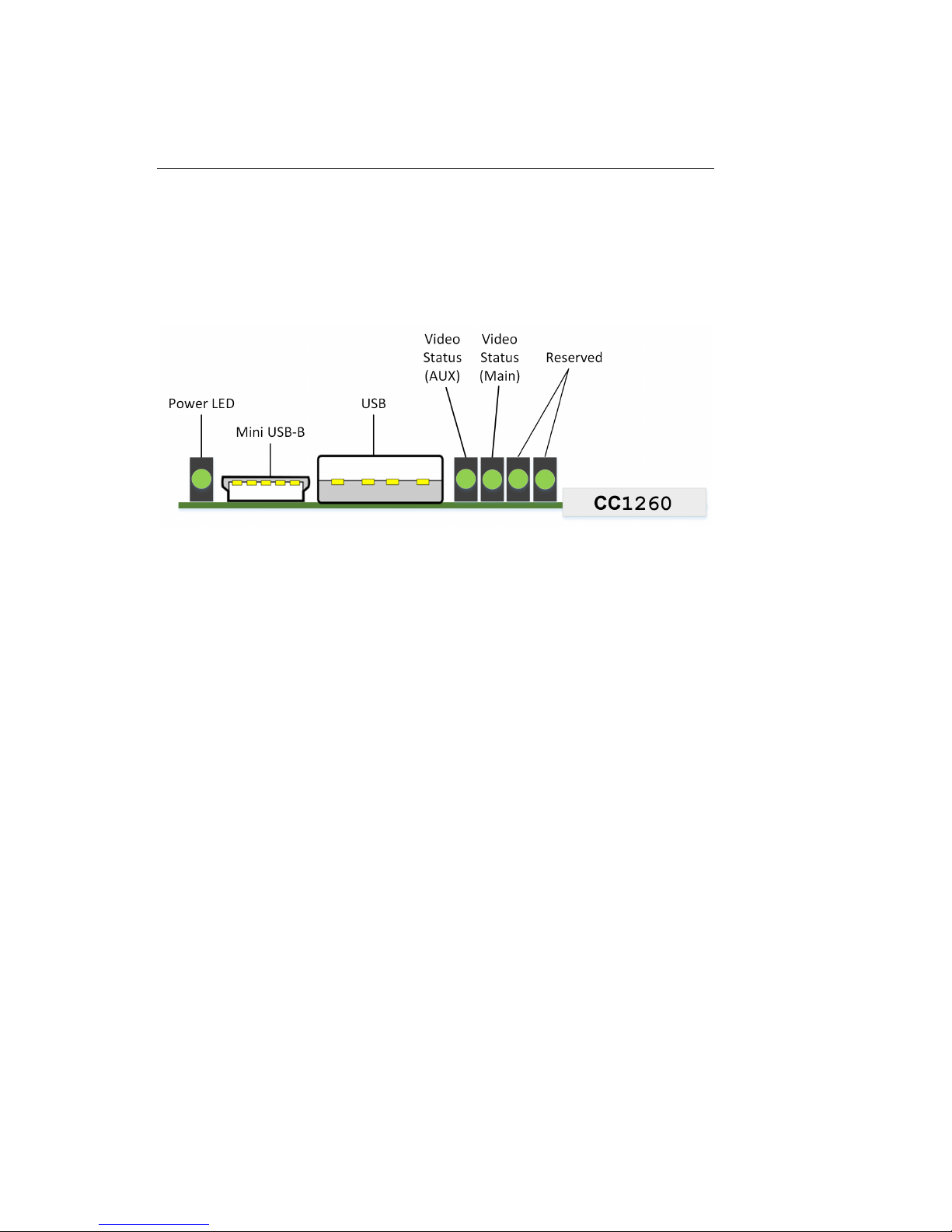
3.1 Front Panel
The front of the CC1260 card is depicted in the following diagram:
Power LED The power LED will be green when the
card is receiving power from the frame.
USB Connectors Reserved for future use.
Video Status (AUX) Reserved for future use.
Video Status (Main) This LED will be red when there is no
video present on the main input. When
HD or 3G video is present, it will be
green, and when SD video is present, it
will be orange.
3.2 DashBoard Menus
The DashBoard software is used to configure settings, networking, and
perform additional basic configuration for the frame card. It can be
downloaded from Ross Video: https://www.rossvideo.com
Once you have successfully installed the DashBoard tool, open the pro-
gram to find information about the CC1260 and to configure your card.
5
CC1260 iCap™ Interface Card
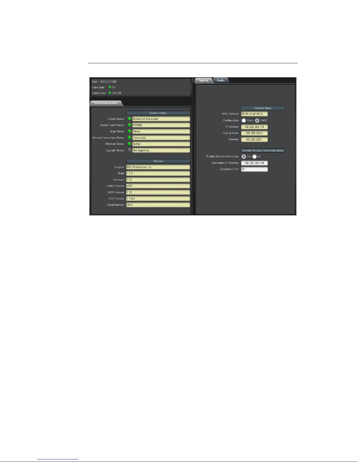
There are two main sections in the DashBoard interface: the Status in-
formation on the left side and the Setup menu on the right side. At the
bottom of the interface, you will find the Upload button, which can be
used to upgrade your CC1260’s DashBoard interface firmware, and the
Reboot button, which can be used to reboot your CC1260.
The upper section on the left shows the card state and the connection
status, each of which has an indicator light and description of the card’s
status. There is a more detailed tab labeled Status Information below
the two basic indicators that provides information about the card’s ver-
sion and its current setup configurations.
In the System Status section, Master Input Format displays the video
type detected on the master video input, including format information
for 3G or HD video. iCap Status indicates whether the card is connected
to an iCap™ server and, if so, whether a captioner is actively connected.
Remote Connection Status indicates whether the card is connected to a
remote encoder via Telnet. The Upgrade Status field displays informa-
tion about whether the encoder is currently loading an upgrade.
6

CC1260 iCap™ Interface Card
The lower section entitled Product displays identifying information about
the hardware and software versions of the card. This section displays
the supplier, the build number, the firmware number, and the ASW ver-
sion to identify the software installed and the serial number of the card.
The setup section in the right half of the interface is broken up into
two tabs: System and Audio.
7
CC1260 iCap™ Interface Card
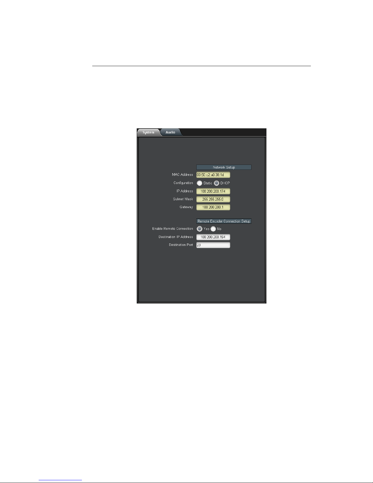
3.2.1 System
The System tab contains network configuration and remote connection
setup fields.
MAC Address Displays the encoder’s MAC address.
Configuration Selects between static and DHCP network
settings.
IP Address Selects the IP address the unit will be as-
signed on your LAN (read-only in DHCP
mode).
Subnet Mask Selects the bit mask used; this should
match the mask used on your LAN (read-
only in DHCP mode).
Gateway Selects the address of the device that the
unit will use to communicate outside of
your LAN (read-only in DHCP mode).
8

CC1260 iCap™ Interface Card
Enable Remote Con-
nection
When set to Yes, the card will attempt to
connect to a remote encoder at the IP and
port specified below, for the purpose of for-
warding incoming iCap™ caption data and
commands.
Destination IP Address IP address of the encoder to which a remote
connection should be established.
Destination Port TCP/IP port to which a remote connec-
tion should be established, at the above-
specified IP address.
9

CC1260 iCap™ Interface Card
3.2.2 Audio
The Audio menu allows configuration and monitoring of audio for iCap™.
Audio Group Selects the SDI embedded audio channel group
that the iCap™mix is sourced from. Up to 4
channel groups can be carried on an SDI sig-
nal, though most commonly Group 1 carries the
primary audio program.
10

CC1260 iCap™ Interface Card
Audio Mix Selects whether the iCap™ mix is being cre-
ated from a Stereo or Surround channel group,
or a single Mono channel. Choose “Stereo” to
select a mix of the left and right channels (1 &
2 or 3 & 4 within the selected Audio Group, ac-
cording to the Stereo Pair setting); “Surround”
to select a mix of the left, right, and center
channels (1, 2 & 3 within the selected Audio
Group); or “Mono” to select one specific chan-
nel.
Stereo Pair Selects whether the iCap™ stereo mix is being
created from channels 1 & 2 or channels 3 & 4
within the selected Audio Group.
Mono Channel Selects an individual channel from which to ob-
tain iCap™ audio when Audio Mix is set to
“Mono”.
Input Level Adjust-
ment (dB)
Adjusts the audio input level without adjusting
the output level of your source. The built–in
digital input trim can boost or cut the audio in-
put level by as much as 12 dB.
Peak Level (%) Dynamically displays the peak signal level at
the audio input. For optimal sound quality, the
peak level should reach at least 60% across the
screen.
11

CC1260 iCap™ Interface Card
3.3 Web Configuration
The Web Configuration interface enables you to access configurations
for your CC1260 applications from any computer on your local network.
Several web applications are installed at the factory: a Startup Setting
editor, a web-based serial-emulation Terminal for entering Smart En-
coder commands, system date/time configuration, and configuration of
iCap™ settings.
Once you have configured your CC1260’s network settings in DashBoard
and connected it to your LAN via the port on the rear module, you can
open up a web browser on any PC on the same local network. Navi-
gate to the IP address that you configured in DashBoard; for example,
type 192.168.1.15 into the address bar of the browser if that is the ad-
dress you entered into DashBoard. If you cannot navigate to the page
in your web browser, check with your network administrator that the IP
Address and Subnet Mask you entered in DashBoard are valid parame-
ters for your network, since individual settings vary.
Once the page has loaded, you will see a list on the left panel of the
different web applications installed on your encoder. Click any of these
links to navigate to the page for that application.
12

CC1260 iCap™ Interface Card
4 Connecting to Remote Encoders
The CC1260 iCap™ Interface Card allows broadcasters and caption ser-
vice providers to enter closed captions into an encoder that does not
directly support EEG’s iCap™ system, while still leveraging many of the
advantages of iCap™. Captioners can connect to the CC1260 using the
same workflow they use with other iCap™-enabled products, while ad-
ministrators can monitor job status and other information via familiar
iCap™ administrative tools.
The CC1260 can clone iCap™ caption data and commands over both
TCP/IP and RS-232. The IP address and port of a remote encoder that’s
accessible over TCP/IP can be entered into the DashBoard interface, as
described in section 3.2.1 above. Serial port P2 simultaneously defaults
to cloning all incoming iCap™ data via RS-232; see the Serial Ports page
in the CC1260 web interface for connection parameters, including baud
rate and parity.
13

CC1260 iCap™ Interface Card
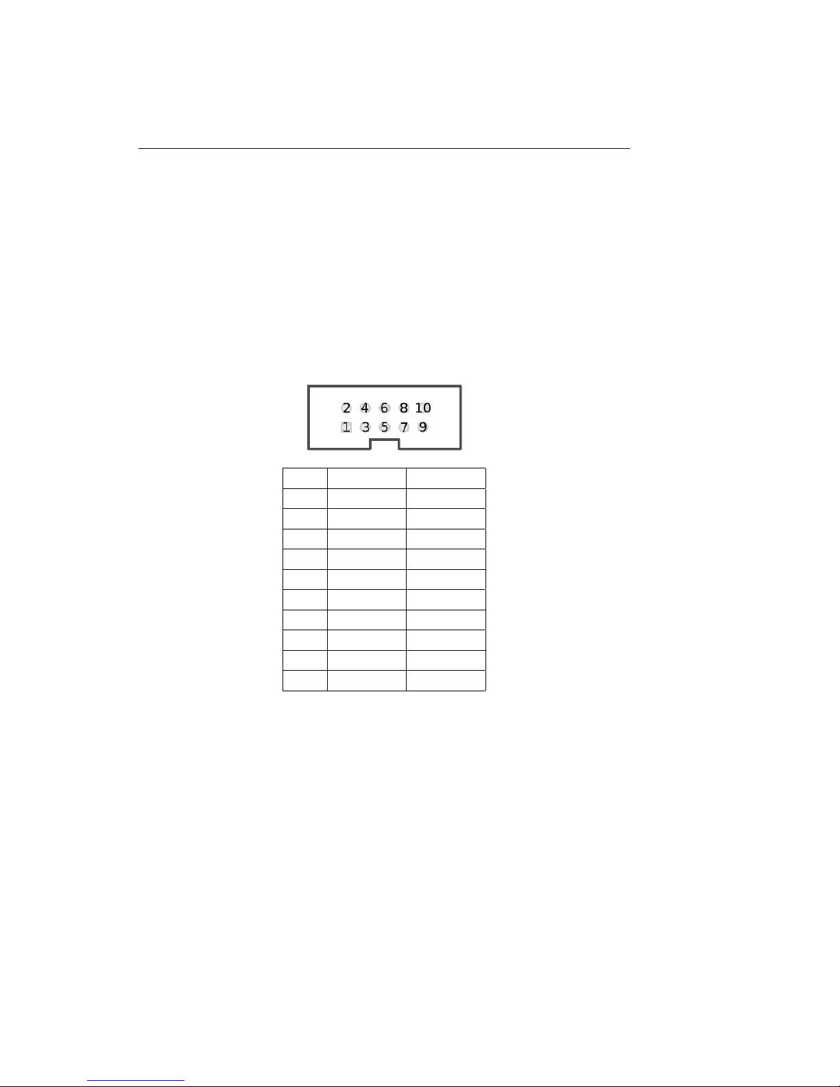
A General-Purpose I/O
Each of the 2 GPIO input banks, Bank A and Bank B, has the following
pinout:
7 8
5 6
3 4
1 2
Bank A provides GPI inputs 1-4:
Input Pins
4 (D) 7, 8
3 (C) 5, 6
2 (B) 3, 4
1 (A) 1, 2
Bank B provides GPI inputs 5-8:
Input Pins
8 (H) 7, 8
7 (G) 5, 6
6 (F) 3, 4
5 (E) 1, 2
A GPI input is activated when closed (connected to ground), and inactive
when open (left floating). The even-numbered pin in a given GPI pair is
its ground. For example, GPI input 1 can be activated by connecting pins
1 and 2 of Bank A, thereby grounding pin 1. If pin 1 were left floating,
GPI input A would be inactive.
A GPI output’s pins form a switch that is on when closed and off when
open. For example, pins 3 and 4 of the GPI output bank form a switch
that is closed when GPI output 2 is active, and open when it is inactive.
14
CC1260 iCap™ Interface Card
B Serial Port Connector
The single-width and double-width rear modules both contain a single
IDC-10 connector, providing the interface for serial ports P1 and P2. P1
can be configured as RS-232, RS-422 (Sony), or RS-422 (EEG), via the
DashBoard interface. P2 operates as RS-232 only. The following image
and table describe the pin mapping from the IDC-10 connector to the
two DB9 connectors that can be used to communicate with ports P1 and
P2:
IDC DB9, P1 DB9, P2
1 5
2 8
3 3
4 2
5 7
6 5
7 8
8 3
9 2
10 7
In RS-232 mode, these ports can be connected directly to a standard PC
serial port with a 9–pin, 3–wire straight serial cable. A ’null modem’ ca-
ble MAY NOT be used for this purpose as it will reverse the connections
of pins 2 and 3.
15

CC1260 iCap™ Interface Card
C Video/Connector Specifications
SDI Video Inputs
Number of Active Inputs 1
Connector BNC per IEC 169–8
Format 2.97 Gb/s SMPTE 424M, 1.485 Gb/s SMPTE
292M, or SMPTE 259M 270 Mb/s
Input Level / Impedance 800 mV p–p ±10% / 75 Ohm
Equalization Automatic up to 100m @ 1.5Gb/s with Belden
1694 or equivalent
Data Input/Output Characteristics
Data Ports 2 DB–9 (one RS-232, one configurable between
RS-232 and RS-422)
Serial Data Format 7 data bits, odd parity, 1 stop bit, 1200 baud
default
GPIO Three 8-pin Molex 87831-0841 connectors: two
containing 4 GPI inputs each, one containing 4
GPI outputs
Electrical
Power 115/230V AC 50/60Hz
Power Consumption 6 W
Physical
Dimensions 12.75” long x 3” wide x 1” tall
Weight < 1 lb.
16
Table of contents
Popular Motherboard manuals by other brands

High Altitude Science
High Altitude Science Eagle Flight Computer manual

Freescale Semiconductor
Freescale Semiconductor PE Micro Cyclone Pro user manual

Nexcom
Nexcom ICES 675 user manual

Asus
Asus ROG STRIX HELIOS user manual

Gigabyte
Gigabyte IM-H410G user manual

EPH Controls
EPH Controls R47 operating instructions


