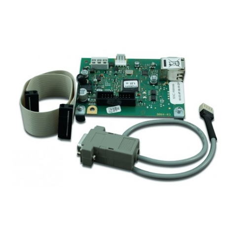
EES MFW Series User manual

M
MF
FW
W-
-Z
ZD
D-
-B
BA
A-
-U
UK
K-
-0
00
06
6
A system from the
MFW product family
Modular 2 wire telecontrol system
Telecontrol over electrically isolated cables

M
MF
FW
W-
-Z
ZD
D-
-B
BA
A-
-U
UK
K-
-0
00
06
6
P
Pa
ag
ge
e
2
2
o
of
f
2
24
4
A system from the MFW product family
Table of contents
1Applicability ....................................................................................................................................... 3
2 General notes......................................................................................................................................... 3
2.1 Symbols used .............................................................................................................................. 3
2.2 Terminology used ........................................................................................................................ 3
2.3 Safety instructions ....................................................................................................................... 4
2.4 Correct and proper usage ........................................................................................................... 5
3 Functional description ............................................................................................................................ 5
3.1 The MFW telecontrol family......................................................................................................... 5
3.2 2 wire line transmission medium .................................................................................................6
3.3 Inputs and outputs ....................................................................................................................... 6
3.3.1 Digital inputs......................................................................................................................... 6
3.3.2 Relay outputs ....................................................................................................................... 7
3.3.3 Analog inputs and outputs.................................................................................................... 8
3.4 Interfaces ..................................................................................................................................... 8
3.4.1 SDP interface ....................................................................................................................... 8
3.4.2 Protocol interface ................................................................................................................. 8
3.5 Connections and indicator lamps ................................................................................................ 9
4Assembly and commissioning ........................................................................................................ 11
5. Configuration via DIP switch ........................................................................................................ 12
5.1 General principles...................................................................................................................... 12
5.2 Master module........................................................................................................................... 12
5.3 Substation module..................................................................................................................... 13
6Parameterisation by PC.................................................................................................................. 14
6.1 Pulse width ................................................................................................................................ 14
6.2 Pulse output module.................................................................................................................. 14
6.3 Static binary inputs / saved statically.........................................................................................15
7Diagnostic functions........................................................................................................................ 16
7.1 “Operating condition” indicator light and signalling relay. ......................................................... 16
7.2 Error codes ................................................................................................................................ 16
7.3 Station fault as a binary message ............................................................................................. 17
7.4 Diagnostics via interface............................................................................................................ 18
7.4.1 Master module terminal commands ................................................................................... 18
7.4.2 Substation module terminal commands............................................................................. 20
8 Technical data...................................................................................................................................... 21
8.1 Terminal assignments ............................................................................................................... 22
8.2 Dimensional drawings ............................................................................................................... 23
9Accessories..................................................................................................................................... 24
© 2007
The copyright of these operating instructions belongs to the manufacturer. They contain technical data,
instructions and drawings for the function and handling of the devices and may not be reproduced in
part or in full or made accessible to third parties.

M
MF
FW
W-
-Z
ZD
D-
-B
BA
A-
-U
UK
K-
-0
00
06
6
P
Pa
ag
ge
e
3
3
o
of
f
2
24
4
A system from the MFW product family
1 Applicability
The description applies to the following MFW modules:
Item number Type as from software version
97BZA1DN0BX0 MF-ZDM12-1PRTU-DIA-0-BX-0 01523004.003.001
97BZA1BN0BX0 MF-ZDM12-1P512-DIA-0-BX-0 01b04003.003
97BZA1ENABX0 MF-ZDM12-1P101-DIA-A-BX-0 05428000.009.000
97BZA3MN0BX0 MF-ZDM12-3PPDP-DIA-0-BX-0 01712000.003.000
97BZAGAN0BB0 MF-ZDM12-G8DEX-DIA-0-BB-0 00b22003.003
97BZAGCN0BX0 MF-ZDM12-G8DAR-DIA-0-BX-0 00b22000.004
97HZA1BN0BX0 UF-ZDM12-1P512-DIA-0-BX-0 01c18000.006
97HZAGAN0BB0 UF-ZDM12-G8DEX-DIA-0-BB-0 00b22002.004
97HZAGAN0BE0 UF-ZDM12-G8DEX-DIA-0-BE-0 00b22002.004
97HZAGAN0BF0 UF-ZDM12-G8DEX-DIA-0-BF-0 00b22002.004
97HZAGAN0BJ0 UF-ZDM12-G8DEX-DIA-0-BJ-0 00b22002.004
97HZAGAN0BB0 UF-ZDM12-G8DEX-DIA-0-BB-3 00b22002.004
97HZAGCN0BX0 UF-ZDM12-G8DAR-DIA-0-BX-0 00b22001.005.000
2 General notes
2.1 Symbols used
The following symbols are used in this documentation:
Safety instruction
This symbol marks warnings, prohibitions and directions relating to hazards. It is essential that
they are observed and obeyed.
Additional note
This symbol indicates additional information and recommendations from the manufacturer.
Important section
This symbol indicates particularly important information.
Cross-reference
This symbol refers to diagrams and to other locations within the document or to other literature.
2.2 Terminology used
MFW
The MFW modular telecontrol network consists of a central station and up to 31 substations. Each
station requires at least one basic module. Up to 15 expansion modules can be connected to this.
Basic module
The basic modules represent the minimum core of a telecontrol station (central station or substation).
They contain at least the following function groups:
•internal modem
•optionally 8 digital inputs or outputs with status LED, or an additional serial interface for protocol
coupling
•SDP-interface for parameterisation, diagnostics and protocol coupling
•one or two CAN bus interfaces for connecting the expansion modules
•Operating status indicator and fault signalling contact
The basic modules are available in two versions – master module and substation module.

M
MF
FW
W-
-Z
ZD
D-
-B
BA
A-
-U
UK
K-
-0
00
06
6
P
Pa
ag
ge
e
4
4
o
of
f
2
24
4
A system from the MFW product family
Master module
In each central station one basic module of the master module version is used. The master module
coordinates the data exchange between the individual stations and has an image of all system inputs
and outputs. At the moment master modules are available with the following type names:
MF-... - standard telecontrol master
MD-...- telecontrol master with data logger function *
Substation module
The substation modules are used in the substations. At present, substation modules with the following
type names can be used:
UF-... - telecontrol substations
UD-... - standard version of the telecontrol substation with data logger function *
UL-... - low power version of the telecontrol substation with data logger function *
Expansion module
Each basic module can be fitted with up to a maximum of 15 expansion modules in order to increase
the I/O range. These are connected via the CAN bus interface.
I/O module
The majority of basic modules have 8 inputs or outputs. These are referred to as I/O modules. In the
same way, the expansion modules contain an I/O module consisting of 8 digital inputs, 8 transistor
outputs, 8 output relays, 4 analog inputs or 4 analog outputs.
Station address
To identify the stations in the MFW system, each substation module is given a station address (1 -31).
The master module is fixed to address 0. Station addresses must be unique.
Module number
Each I/O module is given a module number. The data is exchanged between modules with the same
module number. The physical arrangement of the modules within the system (the station address) is of
no significance at all here. The input module with number 5, for instance, transmits its data to all the
output modules whose number is 5.
* These modules are not available with 2 wire modem.
2.3 Safety instructions
These operating instructions must be carefully read and followed!
Risk of interference with electronic devices!
When operating the telecontrol system close to devices that are subject to interference, the
special regulations for these areas must be observed!
Risk of ignition from electromagnetic fields!
The MFW modules must not be operated in the neighbourhood of inflammable gases or
liquids (fuel depots, petrol stations, chemical works, gas containers etc.)!
Risk of damage!
The MFW modules must not be opened or subjected to improper modification!

M
MF
FW
W-
-Z
ZD
D-
-B
BA
A-
-U
UK
K-
-0
00
06
6
P
Pa
ag
ge
e
5
5
o
of
f
2
24
4
A system from the MFW product family
2.4 Correct and proper usage
The telecontrol system is intended exclusively for the applications described in these operating
instructions.
Any other usage can be hazardous and is forbidden. The manufacturer cannot be held liable for
the consequences of improper use of the MFW modules or for any application that does not
accord with the contents of these operating instructions.
3 Functional description
3.1 The MFW telecontrol family
The MFW telecontrol family features a flexible modular concept which can use practically all the media
available for data transmission purposes, such as GSM networks, landline dial-up lines, dedicated lines,
two-wire control lines, various radio data transmission ranges, optical fibres or LAN and WLAN. A
product of this extensive family is the two wire MFW telecontrol system. It is designed specially for the
integration of widely spread outdoor installations. The MFW can be operated as a fully independent,
cost-effective telecontrol system or as an extension to existing telecontrol interface modules.
In its minimum configuration, the telecontrol system consists of a central station and a substation. In
each station at least one basic module is needed. This includes the following function groups, display
and setting elements:
•internal 2 wire modem
•optionally 8 digital inputs or outputs with status LED, or an additional serial interface for protocol
coupling
•SDP-interface for parameterisation, diagnostics and protocol coupling
•one or two CAN bus interfaces for connecting the expansion modules
•Operating status indicator and fault signalling contact
Each basic module can be fitted with up to a maximum of 15 expansion modules in order to increase
the I/O scope. These are connected via the CAN bus interface. Further information about the expansion
modules can be found in the respective instruction manual.
Each I/O module is given a module number. The data is exchanged between modules with the same
module number. The physical arrangement of the modules within the system (the station address) is of
no significance at all here. The input module with number 5, for instance, transmits its data to all the
output modules whose number is 5.
The data exchange is controlled by the master. All substations are cyclically synchronised with the
master in the query principle. This concerns not only the current input and output values but also the
error information and configuration data. This means that the master is always informed about the
current module occupancy of each substation and transmits the values of one input module’s without
additional parameterisation to all substations, that have an associated output module.
Measuring and set values, messages, commands and pulses are transmitted. With digital I/O
modules, the inputs/outputs DE1- DE4 are switchable between static binary of pulse values. Analog
signals can be transmitted both as 0-10V voltage values or as 0-20mA current values. The recording of
the operating hours is possible with EM-G8DEX-0-B.-0 digital expansion modules.

M
MF
FW
W-
-Z
ZD
D-
-B
BA
A-
-U
UK
K-
-0
00
06
6
P
Pa
ag
ge
e
6
6
o
of
f
2
24
4
A system from the MFW product family
In the event of transmission faults, the system detects the faulty communication and reports it via LED
and relay contact both in the central station and in the respective substation. In addition, a binary
contact can be used to signal availability of all connected stations at any point of the telecontrol system,
if appropriate I/O modules are used. If a serial interface is used, this information can also be evaluated
via this interface. In case of a transmission fault the input and output values of a defective station are
frozen in the state of the last valid transmission. After the cause of the fault has been rectified, normal
operation is resumed automatically.
3.2 2 wire line transmission medium
Any standard signal cable is suitable as transmission medium. The two wire system can be configured
as a line, star or branch system. However the maximum loop resistance, that results from the sum of
the resistance of both individual wires, may not be exceeded. The interference immunity of the 2 wire
data transfer is very high. To avoid undesirable interference through induction of interference pulses
from wires laid parallel to each other, the distance between wire pairs should be selected to as large as
possible in multi-wire lines. The use of cables twisted in pairs is the best solution for this.
To match the MFW to each application (type and length of transmission cable and interference impact)
the transmission level of the input damping of the 2 wire modem can be adjusted by means of a DIP
switch ( “Configuration via DIP switch” section).
The system transmission rate (cycle time) depends on the system configuration and the frequency of
the almost simultaneously changing input states. The cycle time is approximately 1 second plus
approximately 250 ms per substation.
The MFW always transmits the current inputs status at the time of query. The minimum pulse
width/pause, that is required for the secure transmission of a status change, depends on the above
mentioned cycle time. Inputs and outputs 1 - 4 of the digital modules can be used for safe transfer of
short pulses. This ensures that the pulses are reliably transmitted even in the case of longer cycle
times.
The MFW data transfer is made via the telegrams with test information. The basic modules reliably
recognise faulty telegrams and reject them. Any faults delay transmission or interrupt the connection
but don’t lead to incorrect output values.
3.3 Inputs and outputs
3.3.1 Digital inputs
Digital inputs are made with the basic or expansion modules. Each module has 8 inputs which can be
switched via DIP switch or parameterisation via PC to one of the following 4 input types:
Static binary input
The current input status is recorded for each transmission. The status must be present longer than the
cycle time to be sure that the status change is transferred.
Binary input saved statically (only for substation basic modules)
Change to a digital input of the substation’s basic module is recorded and saved in a substation until the
master register’s and confirms the change. Only after this confirmation is it possible to record a new
status on the digital input. All status changes that appear in the meantime are not registered.

M
MF
FW
W-
-Z
ZD
D-
-B
BA
A-
-U
UK
K-
-0
00
06
6
P
Pa
ag
ge
e
7
7
o
of
f
2
24
4
A system from the MFW product family
Pulse input
Inputs E1...E4 can be configured for safe transfer of short pulses. Pulses or counter values are summed
up in the input module until the next station query and transferred as the counter states. Please make
sure that the assigned outputs are also configured as pulse outputs.
The counter values are compared between the MFW master and the substations in order to
monitor the values and to protect against incorrect pulse outputs, for instance when a
communication partner restarts. For this reason, the difference between a pair of sequentially
transmitted counter values must not be > 255.
Hour meter
The inputs E1 and E2 of the “EM-G8DEX-” digital expansion modules can be used as an hour meter. To
do so the inputs have to be configured simultaneously as hour meter and counter value processing
ones. Hour meters are treated the same as all other counter values in MFW. The significance of the
hour meter can be configured ( Operating instructions of the expansion modules ).
The hour meters can only be configured on the “EM-G8DEX-...” expansion module starting from
Software version 01404001.021.000 and not on the basic module.
3.3.2 Relay outputs
The “-ZDM12-G8DAR-DIA-0-BX-0” basic modules have 8 relay outputs. It is possible to change the
outputs A1 ... A4 between “static binary output” or “pulse output” using the DIP switch. The outputs A5
... A8 are used as static binary outputs.
Alternatively the “UF-ZDM12-G8DAR-DIA-0-BX-0” substation modules can be used as pulse output
ones. In this case all 8 output relays are switched to pulse output via software parameterisation.
The output frequency (pulse width /pause) can be matched to the input of the subsequent processing
system via parameterisation. ( “Parameterisation by PC” section)
Please make sure that the pulse frequency on the input module may not be permanently
greater than the output frequency of the output module.
For higher pulses frequencies it makes sense from a durability point of view to use expansion
modules with transistor outputs (EM-G8DAL-0-BB-0) for outputting.

M
MF
FW
W-
-Z
ZD
D-
-B
BA
A-
-U
UK
K-
-0
00
06
6
P
Pa
ag
ge
e
8
8
o
of
f
2
24
4
A system from the MFW product family
3.3.3 Analog inputs and outputs
The expansion modules EM-G4AE0-0-BX-0 and EM-G4AA0-0-BX-0 can be used for transferring
0 ... 10 V or 0 ... 20 mA analog values by connecting them to the basic module using a CAN bus.
Detailed information about the analog expansion modules can be found in the respective operating
instructions.
3.4 Interfaces
There is a 9 pin sub-D socket integrated on the bottom of the basic modules for the SDP interface.
For basic modules with protocol interfaces there is an 9-pin sub D socket integrated in the top of the
module for protocol coupling.
3.4.1 SDP interface
The SDP interface on the bottom of the modules has three functions:
Service - Parameterisation of the module with help of the terminal program e.g. Hyper
terminal in Windows
Diagnostics - Using a terminal program for simple diagnosis and error localisation of the
telecontrol system
Protocol interface - ASCII coupling protocol (AKP)
(Can only be used for modules with IEC 60870-5-101/104 interface)
The ASCII coupling protocol is a simple, open EES protocol for exchanging data between the MFW and
an automation system. We would be pleased to provide you with our separate interface description for
more information on this protocol.
To use the SDP interface as a service or diagnostic one, the hyper terminal program used has to be set
to the following values depending on the MFW module used:
On all other basic modules
•9600 Baud
•8 bits
•1 start bit
•1 stop bit
•no parity
•no flow control
Master module with IEC interface
•115 200 Baud
•8 bits
•1 start bit
•1 stop bit
•no parity
•no flow control
3.4.2 Protocol interface
One of the following standard protocols can be realised via the optional protocol interface in the top of
the module depending on the type:
•IEC 60870-5-101
•Modbus RTU
•Profibus DP
•3964R/RK512
The functional description and parameterisation of the interface can be found in the separate interface
description.

M
MF
FW
W-
-Z
ZD
D-
-B
BA
A-
-U
UK
K-
-0
00
06
6
P
Pa
ag
ge
e
9
9
o
of
f
2
24
4
A system from the MFW product family
3.5 Connections and indicator lamps
Figure 1: Master module with IEC interface
6 Indicator light “Operating condition”
Permanent light- No error
Off - no supply voltage or module defect
flashing - Error ( “Diagnostic functions”section)
1 Protocol interface
(only for modules with serial protocol interface)
2 SDP interface
3 Socket for the prepared Ethernet interface
(only for master module with IEC interface)
4 CAN bus interface
(for connecting the expansion modules)
5 Connecting socket for the DCF77 active antenna
(only for master module with IEC interface)
7 Status LEDs
LED1 TX for data traffic on the two wire (telegram transmission)
LED2 RX for data traffic on the two wire (telegram receiving)
<=> “External module” LED flashes if an expansion module is connected.
<~> LED “DCF77 module”
Flashing once per second - DCF77 reception
Irregular flashing - bad DCF77 reception
Off - no DCF77 reception or no DCF77 receiver connected
8 COM-LED for the serial interface flashes when data is sent to or received by the interface.

M
MF
FW
W-
-Z
ZD
D-
-B
BA
A-
-U
UK
K-
-0
00
06
6
P
Pa
ag
ge
e
1
10
0
o
of
f
2
24
4
A system from the MFW product family
2 SDP interface
4 CAN bus interfaces (for connecting the expansion
modules)
6 Indicator light “Operating condition”
Permanent light- No error
Off - no supply voltage or module defect
flashing - Error
(”Diagnostic functions”section)
Figure 2: Basic module with digital inputs or outputs
7 Status LEDs
<=> “External module” LED flashes if an expansion module is connected.
<~> LED “2 wire” – Signalling of transmitted and received telegrams on the 2 wires
8 LED matrix for status indicator of the substation (only on the master module)
LED off - Station is not configured on the master
( “Configuration via DIP switch”section)
Flashing light - optical signal indicating data exchange with the substation
Permanent light- Station malfunctioning or not accessible
9 Status indicator of “digital inputs or outputs”
Operating mode Input status acknowledged by the
master Led
1 Permanent light
Static binary input or
output 0 Off
Pulse On (for the pulse duration)Pulse input or output
Pause
no influence
Off
0 yes Off
1 no Flashing (900 ms on and 100 ms off)
1 yes Permanent light
Binary input saved
statically
0 no Flashing (900 ms off and 100 ms on)
Table 1: Status indicator of the inputs and outputs of the basic module via red status LEDs

M
MF
FW
W-
-Z
ZD
D-
-B
BA
A-
-U
UK
K-
-0
00
06
6
P
Pa
ag
ge
e
1
11
1
o
of
f
2
24
4
A system from the MFW product family
4 Assembly and commissioning
1. Unpack all the transmission system's modules, and check them for transport damage. Report
any transport damage immediately to the responsible carrier. Please check that the delivery is
complete as per the delivery note.
2. Select mounting locations for the individual stations.
The delivery may contain master module, substation and expansion modules. The
system bus cable for connecting to the basic modules is supplied with the
expansion modules.
3. Configuring the modules “Configuration via DIP switch” section.
4. Engage the basic module and any expansion modules that may be required on the mounting
rail.
5. Connect the 2 wire line and the input and output leads as per the terminal assignment.
The length of the input and output leads should not exceed a maximum of 3 m.
6. If expansion modules are used then connect them to the
basic module with the system bus cable supplied via the
RJ45 sockets in the bottom of the modules. Loop the bus
connection for use with several expansion modules.
Please use the right RJ45 socket for master
modules with IEC interface (see illustration). The
left socket is prepared for use as an Ethernet
connection.
7. Connect the power supply to the basic module. The power supply of the expansion modules is
made via the system bus cable.
The length of the power supply leads should not exceed 10 m.
8. Switch on the power supply. The station is ready for operation once the green LED on the basic
module lights permanently. Please refer to the “Error codes” section if this LED flashes.

M
MF
FW
W-
-Z
ZD
D-
-B
BA
A-
-U
UK
K-
-0
00
06
6
P
Pa
ag
ge
e
1
12
2
o
of
f
2
24
4
A system from the MFW product family
5. Configuration via DIP switch
5.1 General principles
Data within the telecontrol system is exchanged on the basis of module numbers. A module number is
assigned to every basic or expansion module that contains an I/O module. The data is exchanged
between modules with the same module number. The physical arrangement of the modules within the
system (the station address) is of no significance at all here. The no. 5 input module, for example,
transfers its data to all output modules with module no. 5. Several output modules with the same
module no. may be present. An input module number, however, can only be used once within one
system.
The most important settings can be made with the aid of DIP
switches. These can include station address of the substation
(0 – 31), number of substations connected to the master,
module number (0 ... 254), digital I/O operating mode and
current and voltage with analog signals etc. The DIP switches
A and B are located on the bottom of the basic modules.
M
o
dule
numbers
251 ... 254
are reserved for the
output of station errors in the factory
setting.
Figure 3: Bottom of the basic modules
5.2 Master module
The station address is always 0. The following settings are required:
Meaning Values DIP switches
Module number of the I/O
module
0 – 250 A1 –A8
Diagnostic interface switchover ON - diagnostic interface
OFF - protocol interface
A9
Number of substations 1 – 31 B1 – B5
Number of pulse inputs or
outputs
0, 1, 2 or 4
(All other inputs and outputs
are handled as static I/Os by
MFW.)
B6 B7
Pulse input or
output
OFF OFF none
ON OFF E/A1
OFF ON E/A1 and E/A2
ON ON E/A1 – E/A4
2 wire reception level Standard /-20 dB B8
2 wire transmission level Standard / high B9
Table 2: DIP switch of the master module
The DIP switch A9 only functions for modules with switchable interface.

M
MF
FW
W-
-Z
ZD
D-
-B
BA
A-
-U
UK
K-
-0
00
06
6
P
Pa
ag
ge
e
1
13
3
o
of
f
2
24
4
A system from the MFW product family
The setting of the module numbers and the number of connected substations are binary coded.
For example:
A1 A2 A3 A4 A5 A6 A7 A8Meaning
20= 1 21= 2 22= 4 23= 8 24= 16 25= 32 26= 64 27= 128
Module number 2 OFF ON OFF OFF OFF OFF OFF OFF
Module number 7 ON ON ON OFF OFF OFF OFF OFF
Module number 254 OFF ON ON ON ON ON ON ON
B1 B2 B3 B4 B5Meaning
20= 1 21= 2 22= 4 23= 8 24= 16
2 stations OFF ON OFF OFF OFF
7 stations ON ON ON OFF OFF
31 stations ON ON ON ON ON
5.3 Substation module
The following settings must be made
Meaning Values DIP switches
Module number of the I/O
module
0 – 250 A1 –A8
not used A9
Station address 1 – 31 B1 – B5
Number of pulse inputs or
outputs
0, 1, 2 or 4
(All other inputs and outputs
are handled as static I/Os by
MFW.)
B6 B7
Pulse input or
output
OFF OFF none
ON OFF E/A1
OFF ON E/A1 and E/A2
ON ON E/A1 – E/A4
2 wire reception level Standard /-20 dB B8
2 wire transmission level Standard / high B9
Table 3: DIP switch of the basic module
The setting of the module numbers and the station addresses are binary coded.
For example:
A1 A2 A3 A4 A5 A6 A7 A8Meaning
20= 1 21= 2 22= 4 23= 8 24= 16 25= 32 26= 64 27= 128
Module number 2 OFF ON OFF OFF OFF OFF OFF OFF
Module number 7 ON ON ON OFF OFF OFF OFF OFF
Module number 254 OFF ON ON ON ON ON ON ON
B1 B2 B3 B4 B5Meaning
20= 1 21= 2 22= 4 23= 8 24= 16
Station 2 OFF ON OFF OFF OFF
Station 7 ON ON ON OFF OFF
Station 31 ON ON ON ON ON

M
MF
FW
W-
-Z
ZD
D-
-B
BA
A-
-U
UK
K-
-0
00
06
6
P
Pa
ag
ge
e
1
14
4
o
of
f
2
24
4
A system from the MFW product family
6 Parameterisation by PC
The following functions can be parameterised by hyper terminal. To do so the PC has to be fitted with a
1:1 connection cable (9 pin sub D socket/plug) connected to the SDP interface. The setting of the
interface parameters of the hyper terminal program depends on the MFW module type and is explained
in the “SDP interface”section.
The parameterisation commands are listed below. The commands have to be completed with
<ENTER>. This is not mentioned in the following versions, it is assumed.
6.1 Pulse width
If outputs A1 ... A4 of a “ZDM12-G8DAR-DIA-0-BX-0” basic module are configured as pulse outputs via
DIP switches B6 and B7, then the pulse width/pause can be matched to the speed of the subsequent
processing system. Pulse width/pause can be set in 40 ms steps. The parameterised value is also valid
for all outputs of the basic module, which are set to pulse output via DIP switch.
The pulse width can only be set with the parameter “z” when the module is not used as a pulse
output module (Parameter „pipt” = 0).
Syntax
Read parameter: z
Write parameter: z<n>
n -1...256 pulse width = n x 40 ms
Example
Command z ;Query of the set value
Response 1 40 ms
Command z4 ;Pulse width = 4 x 40 ms
Response 4
Factory setting: n = 1 ; pulse width = 40 ms
Please note that during pulse width parameterisation it is not permitted to have permanently more
pulses input than output. This would lead to loss of pulses and may occur if the input frequency is
permanently higher than the output one.
6.2 Pulse output module
If all 8 output relays of a “UF-ZDM12-G8DAR-DIA-0-BX-0” basic module are used for pulse output (e.g.
pulses, which are recorded with an EM-G8DEX-0-BB-E input module or pulse commands for control via
a master with IEC 60870-5-101/104 interface), then these are set by software parameterisation. The
output frequency (pulse width/pause) is defined simultaneously by the parameter. The parameterisation
is always valid for all 8 output relays together.
If a module is used as pulse output one (Parameter „pipt” > 0) the position of DIP switches B6
and B7 is ignored and the parameter “z” is ineffective.

M
MF
FW
W-
-Z
ZD
D-
-B
BA
A-
-U
UK
K-
-0
00
06
6
P
Pa
ag
ge
e
1
15
5
o
of
f
2
24
4
A system from the MFW product family
Syntax
Read parameter: pipt
Write parameter: pipt<n>
n - 0 Use of the outputs according to the setting of DIP switches B6 and B7
1...256 Pulse output module (all outputs as pulse ones)
Pulse width = n x 40 ms
Example
Command pipt ;Query of the set value
Response 1 40 ms
Command pipt4 ;Pulse width = 4 x 40 ms
Response 4
Factory setting: n = 0 ; A1 ... A4 according to the setting of DIP switches B6 and B7
A5 ... A8 static binary output
6.3 Static binary inputs / saved statically
Each digital input of a “UF-ZDM12-G8DEX-...”, which is configured as a static binary input
(Æ“Substation configuration module”section), can be parameterised for the „Binary input saved
statically” operating mode ( Æ“Digital inputs”section). In the factory setting all 8 digital inputs are
parameterised as static binary inputs without saving.
Syntax
Read parameter: t26
Write parameter: r26,<Mask>[,<Refresh time>]
Mask - 8 digit 0/1 string
the 1st digit corresponds with input 8 and the 8th one with input 1
0 - static binary input
1 - binary input saved statically
Refresh time - (refresh time +1) x 10 = time in seconds, after which the saved status of the input is
re-transmitted in case of a query by the master. This continues until the master
acknowledges the receipt of the status change.
Value range 0…255
The refresh time is optional, and does not have to be entered. The previously set value remains if the
entry is not made.
Example
Command r26,00011111,5 ; Inputs 1 -5 binary input saved statically
Inputs 6 -8 static binary input
Refresh time = (5 +1) x 10 s = 60 s
Factory setting: 00000000,0 ; Use of the inputs according to the setting of
DIP switches B6 and B7
Refresh time = 10 s
As soon as one of the 8 digital inputs is configured per DIP switch as a „binary input saved
statically” an “EM-G8DEX-...” virtual module is automatically generated with the same module
number. That is why it is only possible to connect a maximum of another 14 expansion modules to
the basic module.
Parameterisation commands, which are only required for modules with a serial
interface can be found in the relevant interface descriptions.

M
MF
FW
W-
-Z
ZD
D-
-B
BA
A-
-U
UK
K-
-0
00
06
6
P
Pa
ag
ge
e
1
16
6
o
of
f
2
24
4
A system from the MFW product family
7 Diagnostic functions
A variety of diagnostic information is available to monitor and assess the system functions. These
include, for instance, individual station fields indicated via the LED matrix or signalling via relay
contacts, or more detailed information via the diagnostic interface.
7.1 “Operating condition” indicator light and signalling relay.
The “operating condition” indicator light provides information about the current error status:
•Permanent light= no error
•Flashing = fault
•Off = no power supply
The sequence of flashes is composed of:
No. of long flashes Æ1st error code digit
No. of short flashes Æ2nd error code digit
Pause
For example: long, short, short, short, pause = error code 13
When more than one error occurs at the same time, the one with the highest priority is always
the one that is indicated.
In addition to the “operating condition” indicator light, a relay with change-over contact indicates the
state of the station. (The status of the complete system is indicated on the master module).
Contact 14 / 15 closed - power failure or error ( Table of error codes
)
Contact 15 / 16 closed - no error
7.2 Error codes
No Error Comment
12 CAN bus error Communication with an expansion module is disrupted or the
expansion module is faulty.
13 Substation error An error has occurred in a substation.
15 Substation/ master is not
accessible
At least one substation does not respond to the master’s
queries. The error occurs on the substation if it is no longer
queried by the master or when it doesn’t recognise the
telegrams.
61 Serial interface error There are communication problems on the protocol interface.
This errors only occurs for basic modules with a
communication interface.
Table 4: Error codes

M
MF
FW
W-
-Z
ZD
D-
-B
BA
A-
-U
UK
K-
-0
00
06
6
P
Pa
ag
ge
e
1
17
7
o
of
f
2
24
4
A system from the MFW product family
7.3 Station fault as a binary message
In certain applications it makes sense to assign each substation with its own binary output for indicating
the operating condition. Module numbers 254 – 251 are reserved for this purpose. Errors are assigned
to the outputs as shown in the following table. Outputs that are set signal a malfunctioning station. The
output modules required for this can be inserted at any location within the telecontrol system. It is also
possible to insert more than one of these modules.
Module
number
Output
Error in
station
A1 Master
A2 Substation 1
A3 Substation 2
A4 Substation 3
A5 Substation 4
A6 Substation 5
A7 Substation 6
254
A8 Substation 7
A1 Substation 8
A2 Substation 9
A3 Substation 10
A4 Substation 11
A5 Substation 12
A6 Substation 13
A7 Substation 14
253
A8 Substation 15
Module
number
Output
Error in
station
A1 Substation 16
A2 Substation 17
A3 Substation 18
A4 Substation 19
A5 Substation 20
A6 Substation 21
A7 Substation 22
252
A8 Substation 23
A1 Substation 24
A2 Substation 25
A3 Substation 26
A4 Substation 27
A5 Substation 28
A6 Substation 29
A7 Substation 30
251
A8 Substation 31
Table 5: Allocation of the station error messages to the outputs

M
MF
FW
W-
-Z
ZD
D-
-B
BA
A-
-U
UK
K-
-0
00
06
6
P
Pa
ag
ge
e
1
18
8
o
of
f
2
24
4
A system from the MFW product family
7.4 Diagnostics via interface
The SDP interface can be used to obtain additional information about the condition of the system with
the aid of a terminal. The setting of the interface parameters of the hyper terminal program depends on
the MFW module type and is explained in the “SDP interface”section. The following sections list the
commands that can be used to ask for information. Upper and lower-case are ignored in the letters
composing the command. The commands have to be completed with <ENTER>.
7.4.1 Master module terminal commands
Command/synta
x
Function
f<No.> f - Output of the current error (error codes)
f<No.> - Output of the error text belonging to the error number <No.>
For example:
f<ENTER>
Æ
“Error: 12,13”
f12<ENTER>
Æ
“Error: CAN bus error”
f13<ENTER>
Æ
“Error: (1) substation error” ; Error in substation 1
The substation number is only displayed for MF-ZDM12-1P101-DIA-A-BX-0.
u<n> If a substation error is present it can be queried.
<n> is the number of the substation 1...31
The function returns the error code of the substation's current error. Only the most
significant error is ever reported.
For example: u1
Æ
Output of the error by substation 1
12= CAN bus error
v<n> Display of the connection quality
<n> is the number of the substation, 0...30 (address - 1)
The ratio of responses to inquiry telegrams for this substation is returned, expressed
as the figure per thousand (0...999).
The command v cannot be used on MF-ZDM12-1P101-DIA-A-BX-0.
<mnr> Output of the 5 data words of a module as a decimal value
<mnr> - Module number 0 ... 254
For example:
0, 254, 5, 0, 0, 0 ;Module number 0, 1st value = 254, 2nd value =5, 3rd-5th value =0
hl
hl<n>
Output of the overall history or the <n> most current entries. This command can only
be used on MF-ZDM12-1P101-DIA-A-BX-0.
For example:
hl5
Æ
Output of the last 5 history entries
hl
Æ
Output of the overall history
hl0
Æ
Stops the history output
s Outputs the DIP switch settings of the basic module as a 0/1 sequence
1 = ON, 0 = OFF
For example:
Switch= <10000000 >,<10000000 >
< SA1 – SA8>< SA9,SB1 – SB7> Switch at the bottom of the module, the positions
of switches SB8 and SB9 are not output.
i Output of the station address and basic module number
For example: Substations = 1 module number = 0

M
MF
FW
W-
-Z
ZD
D-
-B
BA
A-
-U
UK
K-
-0
00
06
6
P
Pa
ag
ge
e
1
19
9
o
of
f
2
24
4
A system from the MFW product family
m Output of the list of station modules. A line is used for every possible module.
For example:
M<L no.>,<status>,<serial number>,<MNR>,<MType>,<error>
<No.> 0...15 (position of the module in the configuration list)
<Status> 0 = free, 1 = occupied
<Serial number> Hardware serial number of the basic module
<MNR> Set module number
<MTyp> The module type DE, DA, AE, AA
<Error> “Error” or “OK”
l Output of the configuration list for the whole system
For example: L<station address>,<module number>,<module type>,<serial number>
n Output of the hardware serial number
t53
Output of the software version
For example: 01b16000.000.000
Table 7: Master module terminal commands
Data word Analog module Digital module
1 1st analog value Binary value as a decimal value
2 1nd analog value 1st counter value if present
3 3rd analog value 2nd counter value if present
4 4th analog value 3rd counter value if present
5 not used 4th counter value if present
Table 8: Internal illustration of the I/O status of the I/O modules in 5 data words.
Example 1:
On the digital input module with module number 0 the first input is set as a pulse one. The 5 data words
are output as follows:
0, 7, 5, 0, 0, 0
Module number 0
1. Binary value decimal = 7
Æ
”0000110” E1 = 0 (counter input)
E2 = 1
E3 = 1
E4 ... E8 = 0
2. Until now 5 counter values have been registered on input E1.
Example 2:
The first input is set as a current one and the second, third and fourth outputs as voltage ones on the
analog output module number 1. Analog values are saved as standardised ones in the range from 0 ...
10 000. The 5 data words are output as follows:
1, 1000, 5000, 1,10000, 0
Module number 1
1. Analog value = 1000
Æ
2 mA
2. Analog value = 5000
Æ
5 V
3. Analog value = 1
Æ
1 mV
4. Analog value = 10 000
Æ
10 V

M
MF
FW
W-
-Z
ZD
D-
-B
BA
A-
-U
UK
K-
-0
00
06
6
P
Pa
ag
ge
e
2
20
0
o
of
f
2
24
4
A system from the MFW product family
7.4.2 Substation module terminal commands
Command/synta
x
Function
f<No.> f - Output of the current error (error codes)
f<No.> - Output of the error text belonging to the error number <No.>
For example:
f<ENTER>
Æ
“Error: 12,15”
f12<ENTER>
Æ
“Error: CAN bus error”
f15<ENTER>
Æ
“Error: Master is not accessible”
i Output of the station address and basic module number
For example: Address = 1 module number = 0
m Output of the list of station modules. A line is used for every possible module.
For example:
M<L no.>,<status>,<serial number>,<MNR>,<MType>,<error>
<No.> 0...15 (position of the module in the configuration list)
<Status> 0 = free, 1 = occupied
<Serial number> Hardware serial number of the basic module
<MNR> Set module number
<MTyp> The module type DE, DA, AE, AA
<Error> “Error” or “OK”
s Outputs the DIP switch settings of the basic module as a 0/1 sequence
1 = ON, 0 = OFF
For example:
Switch= <10000000 >,<10000000 >
< SA1 – SA8>< SA9,SB1 – SB7> Switch at the bottom of the module, the positions
of switches SB8 and SB9 are not output.
n Output of the hardware serial number
t53
Output of the software version
For example: 01b16000.000.000
Table 9: Substation module terminal commands
This manual suits for next models
13
Table of contents
Popular Control Unit manuals by other brands

Zaber Technologies Inc.
Zaber Technologies Inc. X-LRQ-DEC Series user manual
mercor
mercor mcr 0204 User instruction manual

BLACK NOISE
BLACK NOISE COSMOS user manual

Honeywell
Honeywell ADEMCO 4190SN Installation and setup guide
Vega
Vega plicscom operating instructions

Brooks
Brooks PC125 Installation and operation manual
Crosby
Crosby OMNI-TRIM 900 Series Installation, Maintenance and Adjustment Instruction

Honeywell
Honeywell RV283P installation instructions
iseg
iseg NHS Series Technical documentation
JS Automation
JS Automation MPC3024A user manual
Richmat
Richmat HJC56 Ble manual
BSS Audio
BSS Audio BLU-CP Wiring instructions
