RadiSys EPC-26A/27 User manual

Page 1
11
1. Product Description
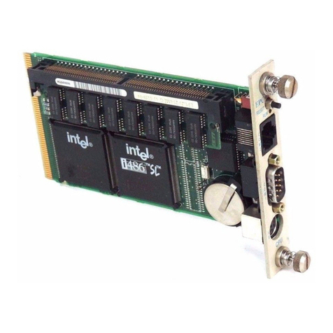
The EPC-26A/27 PC/AT-compatible CPU module is an EMC form factor EPC
based on the DX2 and DX4 Intel486 processor. The EPC-26A uses the 50
MHz Intel486 DX2 CPU, while the EPC-27 uses the 100 MHz IntelDX4.
The EPC-26A/27 uses the Pico-Power Redwood chip set, a two-chip set
packaged in a 176-pin TQFP.
This EPC meets stringent safety and low EMI standards (UL-1950). All front
panel accessible ports have filter networks for reduced EMI and increased
ESD protection.
The EPC-26A/27 processor modules contain the following features:
•The EPC-26A contains an Intel DX2 Enhanced processor (208-pin
SQFP package, 3.3V). The EPC-27 is an Intel DX4 processor.
•One 72-pin 3.3V SIMM socket for memory sizes of 4, 8, 16 or 32 MB
•PC/AT compatible keyboard interface, reset switch and run LED
•Standard PC-compatible peripherals
•Time-of-day clock with 256 bytes of battery-backed CMOS RAM and
user-replaceable battery
•One RS-232 9-pin DTE serial port (COM1) and one RJ45 serial port
(COM2)
•Flashable Phoenix BIOS
•EXM expansion interface
•Optional 2 or 4 MB Flash memory and 128 KB SRAM and watchdog
timer
If your EPC-26A/27 contains the optional Flash/SRAM configuration, you will
also receive a File/Utilities diskette containing formatting software and SRAM
drivers. The software is explained in detail in the XFORMAT Software User’s
Manual that accompanies the diskette.

________________________________________________________________
07-0266-00 June 1995
EPC®-26A/27
Hardware Reference
®
RadiSys Corporation
15025 S.W. Koll Parkway
Beaverton OR 97006
(503) 646-1800
FAX: (503) 646-1850

EPC-26A/27 Hardware Reference
Page ii
EPC and RadiSys are registered trademarks of RadiSys Corporation. IBM
and PC/AT are trademarks of International Business Machines Corporation.
Microsoft Windows and MS-DOS are registered trademarks of Microsoft
Corporation. Intel and Intel486 are trademarks of Intel Corporation.
June 1995
Copyright ©1995 by RadiSys Corporation
All rights reserved.

EPC-26A/27 Hardware Reference
Page iii
Hardware Warranty
RadiSys Corporation ("RadiSys") warrants the EPC system and component
modules to the original purchaser for two years from the product's shipping
date. If an EPC product fails to operate in compliance with its specification
during this period, RadiSys will, at its option, repair or replace the product at
no charge. The customer is, however, responsible for shipping the product;
RadiSys assumes no responsibility for the product until it is received. This
warranty does not cover repair of products that have been damaged by
abuse, accident, disaster, misuse, or incorrect installation.
RadiSys' limited warranty covers products only as delivered. User
modification, such as the addition of memory arrays or other devices, may
void the warranty, and if the product is damaged during installation of the
modifications, this warranty does not cover repair or replacement.
This warranty in no way warrants suitability of the product for any specific
application.
IN NO EVENT WILL RADISYS BE LIABLE FOR ANY DAMAGES,
INCLUDING LOST PROFITS, LOST SAVINGS, OR OTHER INCIDENTAL
OR CONSEQUENTIAL DAMAGES ARISING OUT OF THE USE OR
INABILITY TO USE THE PRODUCT EVEN IF RADISYS HAS BEEN
ADVISED OF THE POSSIBILITY OF SUCH DAMAGES, OR FOR ANY
CLAIM BY ANY PARTY OTHER THAN THE PURCHASER.
THE ABOVE WARRANTY IS IN LIEU OF ANY AND ALL OTHER WAR-
RANTIES, EXPRESSED OR IMPLIED OR STATUTORY, INCLUDING THE
WARRANTIES OF MERCHANTABILITY, FITNESS FOR A PARTICULAR
PURPOSE OR USE, TITLE AND NONINFRINGEMENT. Repair or
replacement as provided above shall be the Purchaser's sole and exclusive
remedy and RadiSys' exclusive liability for any breach of warranty.

EPC-26A/27 Hardware Reference
Page iv
NOTES

EPC-26A/27 Hardware Reference
Page v
Table of Contents
1. Product Description....................................................................................1
Specifications.............................................................................................2
2. BIOS Configuration......................................................................................3
Introduction.................................................................................................3
Installation..................................................................................................3
Insertion in an EXM Carrier........................................................................3
BIOS Setup Screens..................................................................................4
Main BIOS Setup Menu..............................................................................5
IDE Adapter Sub-Menus ....................................................................6
Boot Sequence Sub-Menu.................................................................8
About Drive Letter Assignment................................................9
Keyboard Features Menu...................................................................11
Advanced Menu .........................................................................................12
Integrated Peripherals Sub-Menu ......................................................14
Memory Shadow Sub-Menu...............................................................14
EXM Menu..................................................................................................16
EXM Menu Entries for EPC-26A/27...................................................17
EXM Menu Entries for Additional EXMs.............................................17
Exit Menu ...................................................................................................18
3. Theory of Operation....................................................................................21
Processor and Coprocessor ......................................................................21
Memory ......................................................................................................21
Memory Expansion.....................................................................................22
Memory Map.......................................................................................22
ROM and ROM Shadowing........................................................................23
Battery........................................................................................................23
Jumpers......................................................................................................24
Video Controllers........................................................................................25
Front Panel LED.........................................................................................25
Optional Flash/SRAM Memory...................................................................25
Watchdog Timer.........................................................................................26
Resetting the EPC......................................................................................27
4. Connectors..................................................................................................29
Serial Ports.................................................................................................29
Keyboard....................................................................................................30
EXM Expansion Connector........................................................................30

EPC-26A/27 Hardware Reference
Page vi
5. Troubleshooting & Error Messages .........................................................31
Troubleshooting.........................................................................................31
Common Error Messages..........................................................................32
6. Programming Interface..............................................................................39
Registers....................................................................................................39
Configuration Registers...........................................................40
Addressing Registers..............................................................40
Flash Data Access ..................................................................41
SRAM data access ............................................................................41
Battery Low Condition........................................................................41
SRAM Standard Memory Array.................................................................42
7. Support and Service...................................................................................45
In North America........................................................................................45
Technical Support..............................................................................45
Bulletin Board.....................................................................................45
Repair Services..................................................................................46
Warranty Repairs...............................................................................46
Non-Warranty Services......................................................................46
Arranging Service ..............................................................................47
Other Countries .........................................................................................48
Appendix A: Mechanical Dimensions .........................................................1
Appendix B: Chip Set & I/O Map...................................................................1
Appendix C: Interrupts and DMA Channels ................................................1
Interrupts....................................................................................................1
DMA Channels...........................................................................................2

EPC-26A/27 Hardware Reference
Page 2
11
Specifications
The following table lists the environmental and electrical specifications of the
EPC (with SIMM memory included).
Environmental
Temperature operating 0°to 60°C (* see below)
storage -40°to 85°C
Humidity operating 5 - 95% (non-condensing)
storage 5 - 95% (non-condensing)
Vibration operating .015" Peak to Peak 2.5g (max) 5-2000 Hz
storage .030" Peak to Peak 5g (max) 5-2000 Hz
Shock operating 30g 11 msec duration
storage 50g 11 msec duration
Electrical
Power maximum +5V @ 1.2 A
typical +5V @ 0.8 A
Table 1. EPC Environmental and Electrical Specifications.
* Upper temperature limit degrades 2°C per 1000 ft. elevation. Maximum
elevation 10,000 ft.
NOTE: The EPC-27 requires 200 ft/min airflow for 60°C operation. For
configurations with no airflow, the maximum operating temperature for the
EPC-27 is 43°C.
See Appendix A for mechanical dimensions.

Page 3
22
2. BIOS Configuration
Introduction
The EPC-26A/27 uses the Phoenix BIOS. This section details the various
menus and sub-menus that are used to configure the system. Your system
may be pre-configured and require very little intervention. This section is
written as though you are encountering each field in sequence and for the first
time.
Installation
Before installing the EPC, unpack and inspect it for shipping damage.
DO NOT REMOVE THE MODULE FROM ITS ANTI-STATIC BAG UNLESS
YOU ARE IN A STATIC-FREE ENVIRONMENT.THE EPC,LIKE MOST
OTHER ELECTRONIC DEVICES,IS SUSCEPTIBLE TO ESD DAMAGE.
ESD DAMAGE IS NOT ALWAYS IMMEDIATELY OBVIOUS,IN THAT IT
CAN CAUSE A PARTIAL BREAKDOWN IN SEMICONDUCTOR DEVICES
THAT MIGHT NOT IMMEDIATELY RESULT IN A FAILURE.
ENSURE THAT THE INSTALLATION PROCESS AS DESCRIBED HEREIN
IS ALSO PERFORMED IN A STATIC-FREE ENVIRONMENT.
Insertion in an EXM Carrier
Insertion of the EPC into an EXM carrier is straightforward. Remove a blank
EXM panel from the carrier (by unscrewing the thumbscrews) and insert the
EPC into the card guides. Firmly press the EPC front panel to ensure that the
module is properly seated in the subplane and secure it with the thumb-
screws.

EPC-26A/27 Hardware Reference
22
Page 4
MAKE SURE THAT POWER TO YOUR SYSTEM IS OFF.THE EPC IS
NOT DESIGNED TO BE INSERTED OR REMOVED FROM A LIVE
SYSTEM.
WHEN INSERTING THE EPC,AVOID TOUCHING THE CIRCUIT BOARD,
AND MAKE SURE THE ENVIRONMENT IS STATIC-FREE.
INSERT IT WITH ADEQUATE CONTINUOUS FORCE RATHER THAN
TAPPING OR HAMMERING ON IT.
BIOS Setup Screens
The EPC-26A/27's BIOS contains a setup function to display and alter the
system configuration. This information is maintained in the EPC-26A/27's
nonvolatile CMOS RAM and is used by the BIOS to initialize the hardware in
the EMC chassis.
The BIOS Setup can only be entered during the system reset process,
following a power-up, front panel reset, or equivalent. Press the F2 key when
prompted to enter Setup.
NOTE: The prompt to press the F2 key to enter the BIOS setup can optionally
be suppressed in the BIOS setup. However, you can still press the F2 key to
enter the BIOS setup screens, even if the prompt is suppressed.
Use the up and down cursor (arrow) keys to move from field to field. Use the
right and left arrows to move from menu to menu, as noted in the menu bar at
the top of the screen. If you use the arrow keys to leave a menu and then
return, your active field is always at the beginning of the menu. If you select a
sub-menu and then return to the main menu, you return to that sub-menu
heading.
Fields with a triangle to the left are actually sub-menu headings; press Enter
when the cursor rests on one of these headings to reach that sub-menu. For
most fields, position the cursor at the field and from the numeric keypad,
press the + and - keys to rotate through the available choices. Certain
numeric fields can also be entered via the keyboard. Once the entry has
been changed to appear as desired, use the up and down arrow to move to
the next field.

BIOS Configuration
22
Page 5
Main BIOS Setup Menu
The main BIOS setup menu is shown below:
PhoenixBIOS Setup - Copyright 1992-94 Phoenix Technologies Ltd.
Main Advanced EXM Exit
Item Specific Help
System Time: [16:17:18]
System Date: [03/02/95]
Diskette A: [1.44 MB, 3½"]
Diskette B: [Not Installed]
IDE Adapter 0 Master: (C: 235 Mb)
IDE Adapter 0 Slave: (None)
Video System: [EGA/VGA]
Boot Sequence: [A: then C:]
Numlock: [Auto]
System Memory: 640 KB
Extended Memory: 3072 KB
F1 Help Select Item -/+ Change Values F9 Setup Defaults
ESC Exit Select Menu Enter Select Sub-Menu F10 Previous Values
<Tab>, <Shift-Tab>, or
<Enter> selects field.
EPC-26A/27
Figure 2-1. Main Menu.
The fields in each menu and sub-menu are explained below. Additional help
information is available in the help area on the BIOS setup screen.
System Time:/System Date:
These values are changed by moving to each field and typing in the desired
entry. Use the tab key to move from hour to minute to second, or month to
day to year.
Diskette A:/Diskette B:
This field identifies the type of floppy disk drive installed as the A drive. If the
EPC-26A/27 has a floppy drive installed, the proper setting is usually for a
1.44 MB floppy disk drive. Other options include 360K, 720K, 1.2 MBytes,
and 2.88 Mbytes. If no drive is installed, the proper setting is NOT
INSTALLED.

EPC-26A/27 Hardware Reference
22
Page 6
IDE Adapter 0 Master/Slave Sub-Menus:
These fields are headings for menus that allow you to enter complete disk
drive information. Once the information is entered for the drive, the entry in
the Main Menu shows the drive selected. For more information, turn to the
section concerning the IDE Adapter Menus.
Boot Sequence Sub-Menu
The Boot Sequence Sub-Menu allows you to change the boot delay, boot
sequence, and disable several displays during the boot process, such as the
SETUP prompt, POST errors, floppy drive check, and summary screen. Once
you have set the boot sequence, your choice displays in this entry in the Main
menu. For more information, turn to the section concerning the Boot
Sequence Sub-Menu.
Keyboard Features (Numlock) Sub-Menu
Use this menu to enable or disable various keyboard features, including
enabling the Numlock key, enabling the key click, and setting the keyboard
auto-repeat rate and delay. The Numlock setting displays for this entry in the
Main Menu. For more information, turn to the section concerning the
Keyboard Features Sub-Menu.
There are two more lines on the Main BIOS Setup Screen: “System Memory”
and “Extended Memory.” These are display-only fields set by the BIOS. No
user interaction is required.
IDE Adapter Sub-Menus
There are two IDE adapter sub-menus: one for the master drive and one for
the slave drive. To use an EXM-HD or EXM-MX series mass storage unit, you
must configure a master adapter; the slave is optional, and not relevant to
most RadiSys hardware. To see the detailed characteristics of the device or
to change the device, choose the IDE Adapter 0 Master Sub-Menu to
configure the fixed disk. The following screen displays:

BIOS Configuration
22
Page 7
PhoenixBIOS Setup - Copyright 1992-94 Phoenix Technologies Ltd.
IDE Adapter 0 Master (C: 235 Mb)
Item Specific Help
Autotype Fixed Disk: [Press Enter]
Type: [User] 235 Mb
Cylinders: [723]
Heads: [ 13]
Sectors/Track: [ 51]
F1 Help Select Item -/+ Change Values F9 Setup Defaults
ESC Exit Select Menu Enter Select Sub-Menu F10 Previous Values
Write Precomp: [None]
Figure 2-2. IDE Adapter Sub-Menu.
Autotype Fixed Disk
Use this option when setting up new disks. This option allows the BIOS to
determine the proper settings of the disk based on information on the disk,
which is detected by the EPC-26A/27 BIOS for drives that comply with ANSI
specifications. Use the ENTER key to invoke this function.
Existing (formatted) disks must be set up using the same parameters that
were used originally when the disk was formatted. You must enter the specific
cylinder, head, sector information as listed on the label attached to the drive
at the factory. Use the “User” type described below.
Type
For the majority of users who are using a system that was pre-configured, you
probably have an IDE hard disk drive. Select “None” if you are not using an
IDE hard disk drive. In the case for which you have an IDE disk but cannot
employ the “Autotype” feature, then select “User” for the Type and enter the
correct drive values for cylinders, heads, and sectors/track from the label
attached by RadiSys at the factory.

EPC-26A/27 Hardware Reference
22
Page 8
Note that there are some restrictions when setting up devices on the EPC-
26A/27. If you plan to boot from a non-IDE device, such as the resident Flash
memory, set the master drive as None and use the BIOS extension. You
cannot boot from Flash and still have an IDE drive; the IDE drive must be
drive C: if it is to be used. Flash BIOS extensions are enabled and configured
in the Advanced Menu.
Once you have completed the setup for the IDE Master, you can choose the
IDE Adapter 0 Slave Sub-menu to configure your second drive. When
finished, press the ESC key to return to the Main Menu.
Boot Sequence Sub-Menu
The Boot Sequence Sub-Menu allows you to change the boot sequence
options. The following displays:
PhoenixBIOS Setup - Copyright 1992-94 Phoenix Technologies Ltd.
Boot Options
Item Specific Help
Boot Delay: [0]
Boot Sequence [A: then C:]
POST Errors: [Enabled]
F1 Help Select Item -/+ Change Values F9 Setup Defaults
ESC Exit Select Menu Enter Select Sub-Menu F10 Previous Values
Floppy Check: [Enabled]
Summary Screen: [Enabled]
SETUP Prompt: [Enabled]
Figure 2-3. Boot Sequence Sub-Menu.
Boot Delay:
Use this option to set the system to delay booting for a time period in seconds
that you set. This allows for long start up times on boot devices that spin up
slowly. The default is zero.

BIOS Configuration
22
Page 9
Boot Sequence:
Use this option to define how the system treats floppy drive A: when booting.
You can boot from a floppy in the A: drive or boot directly from the fixed disk
drive. To reduce the amount of time required to boot, set the boot sequence
to use the C: drive only. Note that the C: drive may be an IDE drive or Flash
memory. The options are as follows:
1. A: then C: Used to boot from the floppy disk drive, or if no floppy
is present in the A: drive, boot from the C: drive.
2. C: then A: Used to boot from the C: drive, whether Flash or IDE,
or if none is present, boot from the A: drive.
3. C: only Used to boot from the C: drive without searching for
an A: drive.
The default is A: then C:. The setting chosen here displays in the Boot
Sequence Sub-Menu prompt.
About Drive Letter Assignment
The BIOS determines the boot device algorithmically. First it determines
where the floppy drive fits into the sequence; however, for simplicity here,
assume no A: drive. The BIOS starts by determining if an IDE controller is
enabled. If so, this becomes the C: drive and is expected to be the boot
device.
The BIOS searches memory for enabled mass-storage devices, and builds a
device table. The first device it finds will be the C: drive, and thus the boot
device. The search is performed either prior to IDE installation or after,
depending on the selection in the Advanced Menu.
If an IDE drive is specified in the BIOS setup, it becomes the C: drive. Next,
the BIOS looks for BIOS extensions predefined offsets with C800h to
DFFFFh, up to the maximum of two drives.
There are many different boot options. One supported directly on the EPC-
26A/27 hardware and BIOS is booting from a Flash ROMdisk. For more
information on booting from a Flash ROMdisk, refer to setups in the
Advanced Menu and the XFORMAT Software User’s Manual.

EPC-26A/27 Hardware Reference
22
Page 10
Setup Prompt:
Use this option to enable or disable the message “Press F2 to enter Setup.”
Even if the message is disabled, you can still press F2 to enter the Setup
Menu. The default is to enable this prompt.
POST Errors:
Use this option to stop during the boot if the system encounters error
messages. Otherwise, the system will continue to attempt to boot despite any
startup error messages that display. The default is to enable this option.
Floppy Check:
Use this option to enable or disable the floppy drive search during the boot.
To speed up booting, you can disable the floppy check. It is still possible to
boot from the A: drive even with the floppy check disabled. The default is to
enable the floppy check.
Summary Screen:
Use this option to enable or disable a summary of the system configuration,
which displays before the operating system starts to load. To save time, you
can disable the summary screen. The default is to enable the summary
screen display.
When you have completed the Boot Options Menu, exit back to the Main
BIOS Setup Menu using the ESC key and complete the Keyboard Features
Sub-Menu.

BIOS Configuration
22
Page 11
Keyboard Features Menu
Use this sub-menu to enable or disable various keyboard features.
Figure 2-4. Keyboard Features Sub-Menu.
Numlock
Use this option to enable or disable the Numlock feature of the keyboard. This
enables the use of the keypad numbers. The default is to automatically
engage the Numlock key at boot-up.
Key Click
Use this option to enable or disable the key click feature on the keyboard. If
enabled, the keyboard produces an audible click each time a key is pressed.
Keyboard auto-repeat rate:
Use this option to set the auto-repeat rate if holding a key down on the
keyboard. The rates are from 2-30 per second.
PhoenixBIOS Setup - Copyright 1992-94 Phoenix Technologies Ltd.
Item Specific Help
Numlock [Auto]
Key Click: [Disabled]
Keyboard auto-repeat rate: [30/sec]
Keyboard auto-repeat delay [1/2 sec]
F1 Help Select Item -/+ Change Values F9 Setup Defaults
ESC Exit Select Menu Enter Select Sub-Menu F10 Previous Values
Keyboard Features

EPC-26A/27 Hardware Reference
22
Page 12
Keyboard auto-repeat delay:
Use this option to set the delay between when a key is pressed and when the
auto-repeat feature begins. Options are 1/4, 1/2, 3/4, and one second.
When you are finished with this menu, press ESC to exit back to the main
BIOS Setup Menu.
Advanced Menu
PhoenixBIOS Setup - Copyright 1992-94 Phoenix Technologies Ltd.
Main Advanced EXM Exit
Item Specific HelpRadiSys EPC-26A/27
Integrated Peripherals
L1 Cache: [Enabled]
F1 Help Select Item -/+ Change Values F9 Setup Defaults
ESC Exit Select Menu Enter Select Sub-Menu F10 Previous Values
Memory Shadow
Large Disk Access Mode: [DOS]
Built-in BIOS Extension Configuration
BIOS Extension Base Address
Flash ROMdisk [Not Installed]
Figure 2-5. Advanced Menu.
The Advanced Menu contains settings for integrated peripherals, memory
shadow, large disk access mode, and setting the Flash ROMdisk BIOS
extension base addresses.
Integrated Peripherals Sub-Menu
Use this option to select the Integrated peripherals sub-menu, in order to
configure the COM ports. This does not configure Ethernet, video, or Flash
memory. For more information, turn to the section concerning the Integrated
Peripherals Sub-Menu.

BIOS Configuration
22
Page 13
Memory Shadow Sub-Menu
The term “Memory Shadow” refers to the technique of copying information
from ROM into RAM and accessing it in this alternate memory location. For
more information, turn to the section concerning the Memory Shadow Sub-
Menu.
Large Disk Access Mode:
If using a drive larger than 528 Mbytes, set this to DOS if you are running
DOS, or set this to Other if using a different operating system.
Built-in BIOS Extension Configuration
BIOS Extension Base Address
Flash ROMdisk:
Use this option to enable Flash memory disks on the EPC-26A/27. This must
be selected for the Flash memory to appear as a drive. The base address you
select defines where the Flash ROMdisk BIOS extension is installed.
Options are the following:
DC000-DFFF0h
D8000-DBFF0h
D4000-D7FF0h
D0000-D3FF0h
CC000-CFFF0h
C8000-CBFFFh
Not Installed
Please note that you cannot have an IDE drive if the resident Flash memory is
the boot device. For more information, refer to “About Drive Letter
Assignment”.

EPC-26A/27 Hardware Reference
22
Page 14
Integrated Peripherals Sub-Menu
Use the options in this sub-menu to enable or disable the COM ports.
PhoenixBIOS Setup - Copyright 1992-94 Phoenix Technologies Ltd.
Integrated Peripherals
Item Specific Help
COM 1 [3F8, IRQ4]
COM 2 [2F8, IRQ3]
F1 Help Select Item -/+ Change Values F9 Setup Defaults
ESC Exit Select Menu Enter Select Sub-Menu F10 Previous Values
Figure 2-6. Integrated Peripherals Sub-Menu.
COM PORT/COM PORT
Use this option to enable or disable the COM1 and COM2 ports. The default
for COM1 is 3F8 and IRQ4; the default for COM2 is 2F8 and IRQ3.
When you are finished, press ESC to exit back to the Advanced Menu.
Memory Shadow Sub-Menu
The term “Memory Shadow” refers to the technique of copying information
from ROM into RAM and accessing it in this alternate memory location. The
Memory Shadow Sub-Menu is discussed below.
Table of contents
Other RadiSys Control Unit manuals
Popular Control Unit manuals by other brands

FRC
FRC RTU 1 operating instructions

Interpump Group
Interpump Group Pratissoli S723 operating instructions

Trinamic
Trinamic CoolStep StallGuard2 TMCM-1180 Hardware manual

Bad Cat
Bad Cat The Leash operating manual

BFT
BFT ALCOR N Installation and user manual

Nordson EFD
Nordson EFD 752V Series Maintenance & Parts Guide

Nice
Nice FGD-212 Instructions and warnings for installation and use

FrSky
FrSky D6FR instruction manual

Kobold
Kobold BVB-1101 operating instructions

DMP Electronics
DMP Electronics 277CAN installation guide

GEM
GEM 673 Installation, operating and maintenance instructions

Keysight Technologies
Keysight Technologies J7204A Operating and service manual