EEZ RV EezTire 518SC User manual

EEZ RV PRODUCTS
EezTire 518 SC SYSTEM
WIRELESS TIRE PRESSURE AND
TEMPERATURE MONITORING SYSTEM (TPMS)
Instruction Manual
Model No:51 SC
Handles Up To 26 Wheels
I

NEW 518 SC system is backward
compatible to all previous EEZ RZ TPMS
systems.
Please read this manual thoroughly and
Keep it with you.
It is your responsibility to understand
your system and maintain it.

TABLE OF
CONTENTS
SYSTEM COMPONENTS -ANTI-THEFT SENSORS
------------------------ 04
SYSTEM COMPONENTS -FLOW-THROUGH SENSORS
------------------- 04
MONITOR COMPONENTS
&
ICONS
------------------------------------- 05
TPMS MAIN FEATURES
------------------- - - - -------------- - - - ---------- 05
Reduce Driving Risks -------------- - - ------ - - - -------------- - ----------- 05
Improve Fuel Economy------------------------------------------------- 05
Prolong Lifetime ofTires ------------------ - - ---------------------------- 05
SYSTEM OVERVIEW
-------------- - - - ---------------------- - - - ---------- 06
GENERAL INFORMATION
----------------------------------------------- 06
PRODUCT FEATURES
--------------------------------------------------- 07
Monitor Features ------------------- - - - ----- - - - -------------- - - - ----- - - 07
Sensor Features-------------------------------------------------------· 08
Repeater/Booster Features(optional part) - - ------ - - - ---------------------- - - - 08
SYSTEM SETUP
-------------------------------------------------------- 08
START YOUR SET UP HERE
------------------------------------------- 08
Step1 :Setting Your Systems Alarm Parameters -------------------------------· 09
Step2:Choosing Pressure and Temperature Unit of Measure -------------------- 09
Step3:Choosing per Axle High and Low Parameters --------------------------- 1
0
PROGRAMMING SENSORS TO THE MONITOR
-------------------------- 10
Method 1: Tabletop ---------- - - - ----- - - - ------ - - - ----- - - - ----- - - - ------ - 10
Method 2: Air activation --- - - - ----- - - --------------- - - - ----- - ------------- 11
MONITOR DISPLAY IN OPERATING MODE
---------------------------- 11
MOTES and RECOMMENDATIONS-------------------------------------
11
Factory Defaults
----- - - - ------ - - - ------------- - -------- - - - ----- - - - ----- 12
RESTORE PARAMETERS to FACTORY DEFAULTS
-------------------- 12
MONITOR INSTALLATION
--------------------------------------------- 12
SENSOR INSTALLATION
----------------------------------------------- 14
DELETING A SINGLE SENSOR ID
------------------------------------- 15
DELETING ALL SENSORS ID
---------------------------------------- 15
------------- 02 -------------

OTHER FUNCTIONS
---------------------------------------------------- 16
OUT OF PARAMETER ALERTS
------- - - - ----- - - - ------ - - - ----- - - - ----- - - - 17
Monitor Alerts ---------------------- - - - ------ - - - ----- - - - ----- - - -------17
High-Pressure Alert - - - - - ----- - - - ----- - - - ------ - - - ----- - - - ----- - - - ------17
Low-Pressure Alert - - -------------- - - - ----- - - - -------------- - - - ----- - - - 17
High-Temperature Alert - - ----- - - - ------ - - ------ - - - ----- - - - --------------18
Fast Leakage Alert - - - - - ----- - - - ----- - - - ------ - - - ----- - - - ----- - - - ------ - 18
Sensor Low Battery Alert ---- - - - ----- - - - ------ - - - ----- - - - ----- - - - ------ - - 18
REPLACING ANTI-THEFT SENSOR BATTERY
------------------------- 19
FLOW THROUGH SENSOR BATTREY REPLACEMENT
---------------- 20
REPEATER/SIGNAL BOOSTER INSTALLATION& PROGRAMMING
-------- 21
Recreational Vehicles, Tow Vehicles
&
Trailers
-------------------------- 21
Placement Instructions -- - ----- - - - ----- - - ------- - - - ----- - - - ----- - - - ----- 21
Installation Instructions -------------- - - - ------ - - - ----- - - - ------ - - ------ - 22
Repeater/booster alerts ----- - - - ----- - - - -------------- - - - ----- - - - -------22
SPECIFICATIONS
--- - - - ------ - - - ----- - - - ----- - - - -------------- - - - ----- - - - 23
Monitor --- - ----- - - - ------ - - - ----- - - ------ - - - ------ - - - ----- - - - ------ - 23
Sensors -Anti-Theft --- - - - ------ - - ------ - - - ----- - - - ------ - - ------ - - - ---- 23
Sensors -Flow Through ------------------------------------------------ 23
Transceiver (optional parts) --------------------------------------------- 23
TROUBLESHOOTING
- - -------- - - - ----- - - ------- - - ------ - - - ------ - - ---- 24
CAUTIONS
--------- - ------- - - ----- - - - ------ - ------- - - ------ - - - --------- 29
LIMITED WARRANTY
&
GUARANTEE
---------------------------------- 29
TIRE SENSOR PLACEMENT DIAGRAM
---------------------------------- 30
------------- 03 -------------

SYSTEM COMPONENTS: ANTI-THEFT SENSORS
E-
Monitor
*Sensors
BOOSTER
(optional)
@,
,Q
Monitor Holder
0
Sensor Waterproof
Rubber Seal
(Spare Part)
Item Q'ty
Monitor lpc
Monitor Holder lpc
Suction Cup lpc
Power adaptor lpc
Type-C power cable lpc
n
i-
Power adaptor Bracket&
Screw
Suction Cup
Wrench Type-C power cable
Item Q'ty
Bracket & Screw
1pcs/2pcs
*Sensors Depends on customer request{10~26pcs}
Seng_����t�.!:�roof Sa me as sensor
Wrench 2pcs
Transceiver Depends on customer request(optional)
*Sensors quantity depends on customer requirement, maximum can code up to 26sensors.
SYSTEM COMPONENTS: FLOW -THROUGH SENSORS
Monitor
*Sensors
Transceiv�r
l optional)
Q Monitor Holder Q � ��&
I
lolder screws
Suction Cup
Power adaptor
0
Sensor Waterproof
Rubber Seal
(Spare Part)
Item Q'ty
Monitor lpc
Monitor Holder 1pc
Suction Cup lpc
Power adaptor lpc
Type-C power cable 1pc
r--
r--
Hex Wrench Type-C power cable
Item Q'ty
*Sensors Depends on customer request(10,.,26pcs}
Sensor Waterproof
Rubber Seal Same as sensor
(Spare Part)
Hex Wrench 2pcs
Transceiver Depends on customer request(optional)
*Sensors Quantity depends on customer requirement, maximum can code up to 26 sensors.
04 ---------------

MONITOR COMPONENTS AND ICONS
SET
CODE
C
TPMS MAIN FEATURES
Reduce Driving Risks
T
tON Power
iQFF Switch
Power
Socket
Icon
-
°F/°C
BAR/PSI
(l)
8
(ii[:
§§§
ID
888 888
Monitor Holder
Description
Tire Indicator
Temperature Unit
Pressure Unit
Alert Icon
Sensor Low Battrey Indicator
Monitor Battery Indicator
Booster Icon
It was reported that an astonishing 75% of all running tires in the USA are
under-inflated and 70% of fatal traffic accidents were caused by tire blow-
outs. With a Tire Pressure and Temperature Monitoring System (TPMS),
drivers are warned of abnormal tire conditions before it becomes dangerous.
Improve Fuel Economy
Today's tire designs make visual inspection of deflated tires very difficult.
Very often, a 30% under inflated tire looks very much like a fully inflated one.
A TPMS will make sure your tire pressure is at its proper level.
A 9 psi drop in tire pressure will cause approximately a 4% increase in fuel
consumption.
Prolong Lifetime of Tires
The following table shows a simple relationship between tire pressure and
tire lifetime:
Tire Pressure Tire Lifetime
20% under inflated 30% less
30% under inflated 45% less
20%
over
inflated 10% less
-------------- 05 --------------

SYSTEM OVERVIEW
This EEZ RV PRODUCTS EezTire SlOC Tire Pressure and Temperature
Monitoring System (TPMS) is a heavy duty versatile system designed to
operate on a variety of vehicles. (i.e. Motor Coach, 5th Wheel, Travel Trailer,
Auto, Trailer, Big Rig, Farm and Mining Equipment).
The system comes with a monitor that can handle 26 wheels with pressures
up to 210 psi. The sensors are lightweight and do not affect the tire balance
and have easy to change replaceable batteries. The system offers a method
of dropping either the towing vehicle or the towed vehicle separately. This
allows you to monitor the towing vehicle without a towed or the towed
when driving away from the towing vehicle.
The monitor scrolls automatically through each wheel measuring tire
pressure and temperature, displaying it on the monitor. Alarms can be
preset by the operator so visible and audible alarms can warn the driver of a
catastrophic failure (rapid air pressure loss), high or low pressures and high
temperature. The alarms and monitoring are sent wirelessly in real time to
the cab allowing the operator to monitor tires that are out of their vision. The
audible alarm eliminates the need to watch the monitor continually.
Tire Pressure can be displayed in PSI or Bar and temperature in Fahrenheit
(°F) or Celsius (°C ). Pressure alerts can be set to a different pressure setting for
each axle, so additional towed trailers or vehicles are no problem. The high
efficient sensors can transmit to distances up to 53 feet without a booster
and are easy to install. If needed, an optional booster can be purchased from
your dealer or at www.eezrvproducts.com.
The monitor has a rechargeable Lithium Ion battery and can be used as a
hand held wireless tire pressure monitor when the operator walks around
their vehicle. Sensors come with either the Anti-Theft security feature or
Flow-Through feature, and the monitor comes with both an auxiliary charger
and a hard wire cable at no extra charge.
The EEZ RV PRODUCTS EezTire 518 SC TPMS System offers both easy
installation and one of the largest LCD monitors on the market.
GENERAL INFORMATION
A tire professional or your owners manual should be used to determine the
proper tire pressure for your vehicle. Recommended operating tire pressures
should be set when the ambient temperature is low or cold.
Dramatic changes in tire pressure can occur because of; increased or
decreased ambient temperature, tire contact surface temperature, wheel and
axle loads, sun shining on a particular side, etc. These and other conditions
should be taken into consideration when setting initial tire operating
pressures.
This system cannot warn you of side wall failures; however, it can
------------- 06 -------------

supply you with irregular pressures and temperature information that may
help to prevent this. If the monitor is shut off overnight simply switch the
monitor back on before departure and your real-time tire pressures and
temperatures will be updated and typically appear on the screen within 5
to 10 minutes. Even if the monitor is in the sleep mode the system is always
monitoring and will alarm should any pressure settings or temperatures be
out of your set parameters.
The Schrader Valve (core -inside the valve stem) should be the correct size,
be in good condition and be able to be depressed fully to allow the release
of air to the sensor so it can operate. Some valve stem extensions may
cause inaccurate readings if they do not enable the sensor to work correctly,
metal bodied stems, or T-Valve type is recommended for best performance.
Should you have difficulty with a pressure sensor not working properly, we
recommend that you contact a tire professional to ensure that the tire stem
and Schrader Valve are installed and operating properly. If using internal
tire sealants or balancing compounds/beads check with the manufacturer
to ensure they are compatible with TPMS systems or that you have filtered
valve cores installed. Over a period, tires may lose pressure naturally, through
the tire itself or for other reasons such as rim leakage, etc. After installing the
sensors on a tire valve stem, it is recommended to perform a soapy water
test using 1/4 dish soap and 3/4 water. Spray the soapy solution on the valve
stem and sensor area to ensure the sensor is seated all the way. If air bubbles
are seen in any of these areas, the tire may deflate. The wheel sensors are
weatherproof and can be run in the rain.
Purchasers of this product should not solely rely on this tire pressure
monitoring system for safety and should check the condition and pressure of
their vehicle-s tires on a regular basis as described by the manufacturer of the
vehicle or tire manufacturer. Please note, the EEZ RV PRODUCTS EezTire SlOC
TPMS System operates on an RF system, as with many RF tire systems this
system can occasionally suffer from interference depending on the location
of the system; thus causing the system to be inaccurate or not operate at
all. Tire pressures and temperatures are not the only things that can affect
tire safety; we suggest daily visual inspections and periodic checks by tire
professionals.
PRODUCT FEATURES
Monitor Features
• Reliable and easy to install.
• Large 3 1/2 inch LCD screen.
• Built-in rechargeable lithium ion battery.
• Automatic light sensor and backlight.
• Built in motion sensor.
• Configurable high/low-pressure warnings.
• Configurable high-temperature warnings.
------------- 07 -------------

• Visible and audible alerts.
• Selectable pressure units.
•
Can monitor in either standard or metric measurements (psi or bar/ °For °C )
• It monitors up to 26 tires maximum.
•
Long range between sensors and monitor.
• Per axle measurements can be configured on the tractor and trailer.
Sensor Features
• Reliable cap sensors, easy to install.
• Water resistant.
• Replaceable sensor batteries.
• Fast leak alert.
• Individually coded sensors.
• Anti-theft or flow-through design.
Repeater/Booster Features (optional part)
•
Maintains signal stability.
• Records sensor ID, trailer ID and tire pressure and temperature limits.
• Transferable trailer sensor data between monitor and transceiver.
• Visible and audible alerts.
•
Fixed alarm for high temperature (194°F)
SYSTEM SETUP
This portion is designed to make the set-up of your new EEZ RV PRODUCTS
EezTire 518 SC TPMS System easier and faster.
Much of the information contained in this manual is found through real life
experience using the system and passed on to hopefully make the utilization
of the system easier for you.
Please read through the guide thoroughly before starting. Complete set-up
should take approximately 20 minutes.
EEZ RV PRODUCTS EezTire 51 BC SYSTEM
START YOUR SET UP HERE- Step by Step Instructions:
1. Unpack all of the components of your TPMS System and ensure it is
complete.
2. Take the number kit from the accessory pack and number all your
sensors as indicated below.
(HintAfteraffixingthenumbertothesensortakesomeclearnail
polish and paint over the number. This will help ensure it stays on in inclement weather conditions.)
3. On the diagram on the last page of this manual assign the numbered
sensors to each tire as they will be put on your rig and tow vehicle.
ffi ffi
,-::--ffi
---
]
-------------- 08 --------------

4. Program the alarm parameters using
STEP 1: SETTING YOUR SYSTEMS
ALARM PARAMETERS
5. Program each sensor to the monitor using
STEP 2: PROGRAMMING
SENSORS TO THE MONITOR
STEP 1: SETTING YOUR SYSTEMS ALARM PARAMETERS
Refertothediagramonthe/astpageofthismanualwhereyouwrotethesensornumberforeach tire.
1. Next to each axle write down what your tire pressure is by axle and calculate
what your alarm setting will be.
2. High-Pressure setting will be (200/4 above axle tire pressure).
3. Low-Pressure setting will be (1 QOJb below axle tire pressure).
Example: Front Axle lire Pressure is: 100 psi
High-Pressure Alann Setting will be: 120 psi (100 psi x 1.20 (or 20%) = 120
Low-Pressure Alarm Setting will be: 90 psi (100 psi x .9 (or 90%) = 90
These are industry standards for the initial set-up, some adjustment may be
needed after your first trip. Every brand of tire operates differently, when
some brands reach operating temperature the psi will increase 5 psi, other
brands may increase 20 -22 psi. During your first trip, you will see if you need
to increase your High-Pressure Alarm setting. For the temperature, it is
recommended leaving it at the factory default of 158 degrees F.
STEP 2: Choosing Pressure and Temperature Unit of Measure
1. Press the
SET
button and hold it until you hear the beep. You will first see PSI
or BAR (for metric) in the first window. Use the + or - key to scroll between the two.
When the one you want to use appears in the screen press and release the SET
button. (Pressing and releasing the SET button in this mode is like saying yes to
what the
screen is showing you)
lffiiI:
cc
--- ----
-- ----
lffiiC
cc
--- ----
-- ----
2. It will automatically move to the next window which will show you
°
F
(Fahrenheit) or
°
C (Celsius) for the degree setting in the second window.
Use the + or -key to scroll between the two. When the one you want to
use appears in the screen press the
SET
button and release.
Press the set button again and
"
°
F"
will be flashing. Press+ or-to change to "
0
C"
if you like. The next time that you press the set button the front axle will be
flashing and the words "HIGH PRESSURE" will be displayed. Follow the
instructions below.
------------- 09 -------------

lffiiI:
cc
--- ----
-- ----
lffiiI:
cc
--- ----
-- ----
STEP 3: Choosing per Axle High and Low Parameters
Using the plus or minus keys scroll to your "HIGH' pressure. When you reach your desired
pressure press and release the "SET' button again and 'LOW PRESSURE' will be displayed.
Use the plus or minus keys to set your low pressure. Press the set button again and the next
axle will flash "HIGH PRESSURE". Make your adjustments the same way as for the first axle.
Skip any axles that you are not using and just keep hitting the "SET" button until you get to the
axle that you want to set.
When you have finished setting your
parameters PRESS and HOLD the SET button
until the monitor beeps and you are back to
display mode. Keep in mind that the monitor
will time out in 40 seconds. So wright down
your settings before you start.
PROGRAMMING SENSORS TO THE MONITOR
METHOD 1 tabletop (this is the easiest way)
1. Using the switch on the right side center of the monitor, push it up to turn on the monitor.
Place the monitor flat on the table in front of you. Then place your numbered sensors on the
table about a foot away from the monitor.
2. Press and hold the CODE button on the monitor left side middle button until you hear the
beep. At this time, you will see all 26 tires on the monitor screen, and the right front tire should
be flashing.That is tire number 1. Following your diagram on the back of your manual, place
the first sensor on the table touching the base of the next to the SET button. You will see "FFF
FFF" on the screen . All F's means that a sensor is not programmed yet to that location. Then
press and release the code button very quickly one time. The monitor will beep, and the
sensor's code will be displayed. Press the plus button to go to the next tire and do the same
and so on until all sensors are programmed.
3. When you have programmed the last sensor, press the "CODE" button down until the
monitor sets off the alarm or just turn the monitor off. Then turn the monitor on again to make
sure the tires are programmed in the wright position.
4. Install your sensors to the valve stems in the order that you programmed them. Give the
monitor 5 to 1 O minutes to register all the sensors. Once the sensors are synced you will not
have to re-sync unless you turn off the monitor. You can leave the monitor turned on by the
monitor's battery power. The monitors internal battery will run for 60 hours or 30 days between
charges.
NOTE:
If you get an ID LF (low frequency), error code, hit the sensor hard on the table
to wake it up and repeat. If you still get the Id LF repeat, press the CODE button
and release, pause and then press the CODE button and release again. If it still
gives ID LF then check the battery voltage with a volt meter. The voltage on a
fresh battery should be 3.3v. If it is below 2.9v replace the battery with a fresh
one.
10 ---------------

Method 2: AIR ACTIVATION
1. Using the switch on the left side center of the monitor push it up to turn on the monitor.
2. Place the sensors on the tires as numbered on your diagram but do not tighten them yet.
4. Press and hold the "CODE" button on the lower right side down until you hear the monitor
beep. At this time, you will see all 26 tires on the monitor screen and the right front (number
one) tire should be flashing.
Place the monitor within 3 inches of the sensor and screw the sensor all the way on. Wait a
few seconds and the monitor will beep and a sensor code will be displayed. If it does not
press and release the "CODE" once. Once coded go to the next tire and repeat the steps
making sure to press the plus button to go to the next tire.
YOUR SYSTEM IS NOW SET-UP AND READY FOR USE
If you have problems, see trouble shooting page.
MONITOR DISPLAY IN OPERATING MODE
After the sensors have all been programmed and the system is in operating
mode the monitor display will automatically scroll through each monitored
tire one by one. The tire being transmitted will flash on the screen, and the
pressure and temperature for that wheel will be displayed on the monitor.
When the monitor is initially turned on it may take up to 5 minutes for the monitor and sensors to sync up
before the pressure and temperature will show up on the monitor. Wait for all the tires to read before driving
off.
After this time if you see one sensor is still not transmitting the pressure and
temperature you may want to delete the sensor from the monitor and
reprogram it.
On an initial set up, if the tire still fails to indicate a pressure and temperature remove the sensor and back the
Schrader Valve (valve core) out approximately 1/8 to 1/4 turn and reinstall the sensor. This will ensure there is
sufficient contact and air pressure to the sensor.
NOTES and RECOMMENDATIONS:
-There will be an audible single"chirp': and the tire will flash if the
monitor has not received a reading from that tire after 30 minutes.
-You can also manually scroll through the tires one by one by pressing the
+or -button. If you manually select a particular tire the monitor will
show its readings for 10 seconds.
11

The monitor comes equipped with a light sensor; the backlight will
typically come on if the vehicle is in motion and the light level is low
enough. You may also wave your hand in front of the monitor to
manually activate the backlight or by pressing any button. It can be
turned off by pressing the+ button for 3 seconds. The light sensor
is located on the lower left of the monitor, just left of the "LINK" button.
The monitor comes with a built-in motion sensor; it will go to sleep
(energy saver mode) if there is no movement of the vehicle detected for
approximately 15 minutes and wake up when it detects movement.
It is recommended that the monitor is shut off when the system is not in
use, or you are staying in the vehicle overnight.
-When external power is applied to the monitor it will override the
manual on/off switch on the left side. If you hard wire your system
charger to a "keyed" switch the system will go off when the keyed power
is turned off. If you are using the auxiliary charging cord, you will have to
unplug the charger manually.
-You
will
get a longer service life from your monitor-s internal battery
if you disconnect the external power source and allow the battery to
deplete through normal operations every couple weeks naturally.
The factory default settings are as follows: High Pressure (175 PSI), Low
Pressure (100 PSI), Temperature (158 °F). To restore Factory Defaults: Turn off
the monitor; press the SET button and activate the monitor at the same time.
The RED light will flash, and factory settings will be restored.
Pressure Unit: PSI
High Pressure: 175 psi (12.1 BAR)
Low Pressure: 100 psi (6.9 BAR)
Temperature Unit OF
High Temperature: 158 °F (70 °()
RESTORE PARAMETERS to FACTORY DEFAULTS:
Turn off the monitor; press the SET button and activate the monitor at the same time.
The RED light will flash, and factory settings will be restored.
Pressure Unit: PSI High Pressure: 175 psi (12.1 BAR) Low Pressure: 100 psi (6.9
BAR) Temperature Unit: OF High Temperature: 158 °F (70 °()
MONITOR INSTALLATION
Your system comes with three mounting options: a plastic tower with suction
cup mount for window or dash, low profile mount for dash, low profile triangle
mount for dash. Some people prefer to use Velcro or the small bean bags used
for cell phones on their dash.
12 --------------
HIGH LOW PRESSURE
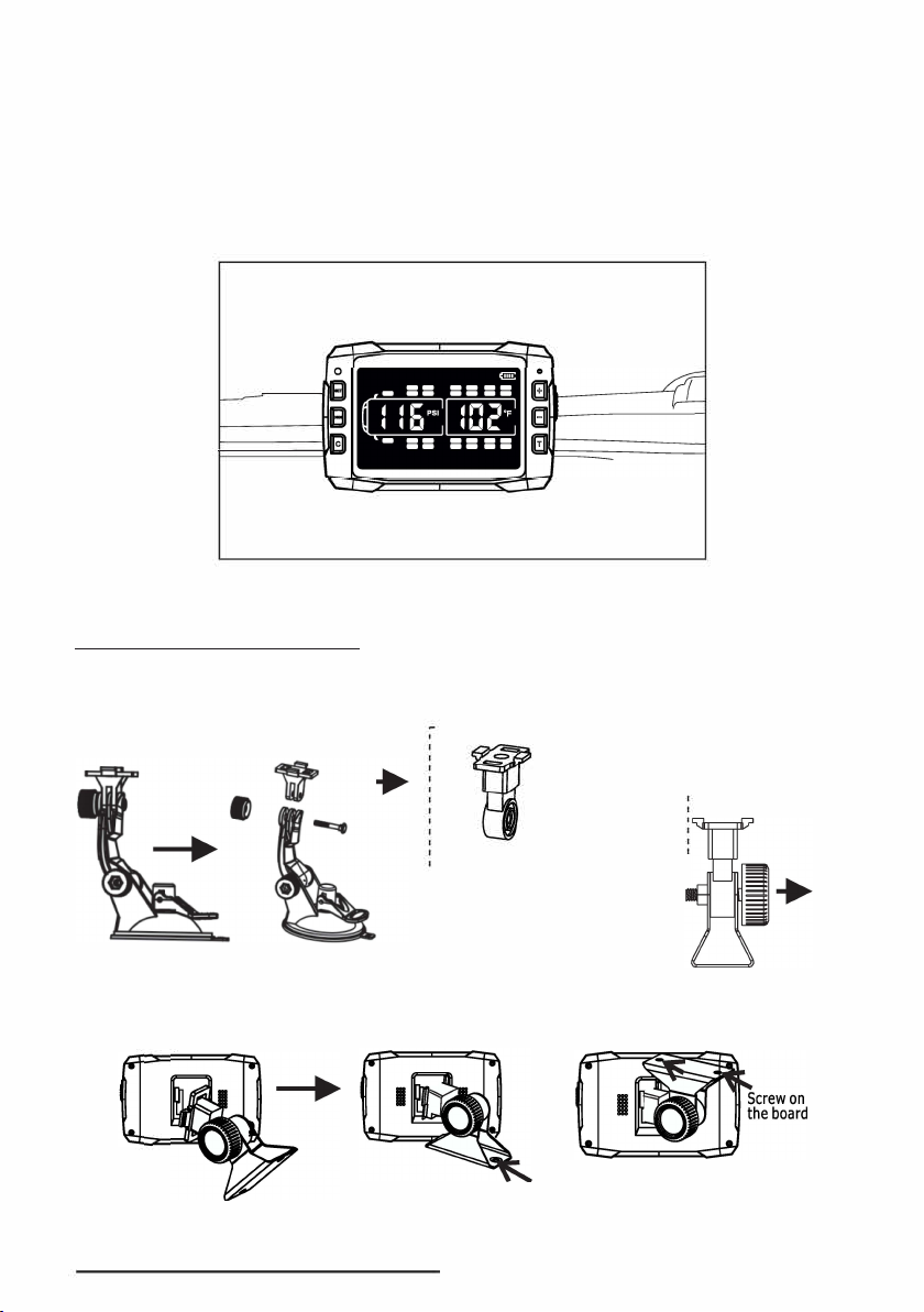
1.mount it onto the windscreen or left side window using the suction cup provided
ensuring you do not obstruct the driver's vision of the road.
2. Plug the power adapter into the cigarette lighter or auxiliary power outlet and
connect the power cable to the monitor. Ensure the pin is aligned straight when
inserting it into the right side of the monitor. When hard wiring it is recommended
using a "keyed" power source.Metal Triangle Mount Bracket If the bracket is needed,
please follow the instructions below. Be sure not to obstruct the driver's vision when
the monitor is installed.
Metal Triangle Mount Bracket
If the bracket is needed, please follow the instructions below. Be sure not to
obstruct the driver's vision when the monitor is installed.
I
- - - - - - - - - - - - - - - - - - - - - - - -
I
Remove this part from ,
suction cup and install :
in the bracket ,
I
-e
-- - - - - - - - - - - - - - - - - - - - - - _
I
�-
Jt
- - - ; - ;-B
-r�c�: t1
-+
I I
I I
I I
I I
I I
I I
_____________ ..
Screw on the dashboard
13 ---------------
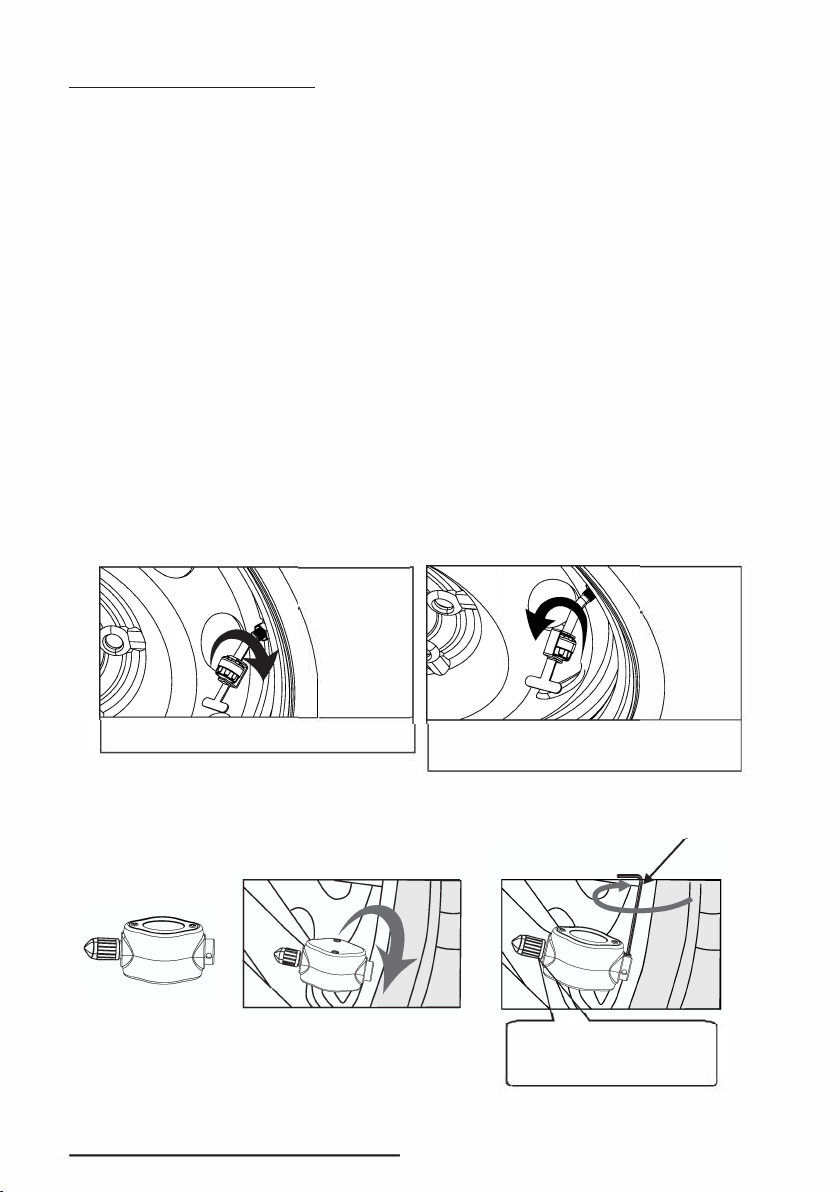
SENSOR INSTALLATION
1. Remove the tire valve cap and mount the corresponding sensor on the
valve stem using the wrench provided.
2. The sensor is designed to be difficult to remove without using the
wrench provided.
3. Simply screw the wrench clockwise.
NOTES:
7.
lfyou have trouble getting the wrench into the location, you can unscrew the two halves of the
Anti-Theft housing, keep the bottom part of the housing in place on the sensor and screw the
sensor onto the valve stem by hand. Once the sensor is in place, pull the lower part of the housing
up and screw the top half of the Anti-Theft housing onto it. The Anti-Theft housing will now spin
when turned on the sensor. The reverse can be done to remove if necessary.
2. If you do not need the Anti-Theft function, you may remove the Anti-Theft cover by just
unscrewing the two halves. Mount the inner sensor on the valve directly. If you do not use the
Anti-Theft housing, itis recommended to put a small bead of silicone around the seam where the
sensor unscrews to replace the battery. This will give extra protection against moisture entering
the battery housing in inclement weather.
Anti-Theft Sensor
Install the sensor onto tyre valve clockwise. Use the spanner provided to screw the
hex nut to the sensor and tighten it.
Flow-Through Sensor
*Do not over tighten the sensor
cap to prevent possible damage
to the sensor.
Hex Wrench
User can inflate or deflate
your tire from the sensor valve
and without taking sensor off.
14 ---------------
DELETING A SINGLE SENSOR ID
1. In operating mode, press and hold the CODE button for 3 seconds,
release it after the beep to enter the coding mode. A flashing tire icon
and ID code are displayed. Press the+ or -button to select the desired
tire.
2. Press and hold the SET button for 3 seconds. A double-beep sound
will be issued, and you will see FFF FFF after the sensor code is deleted
successfully. To return to operating mode, press and hold the CODE
button for 3 seconds until you hear a beep.
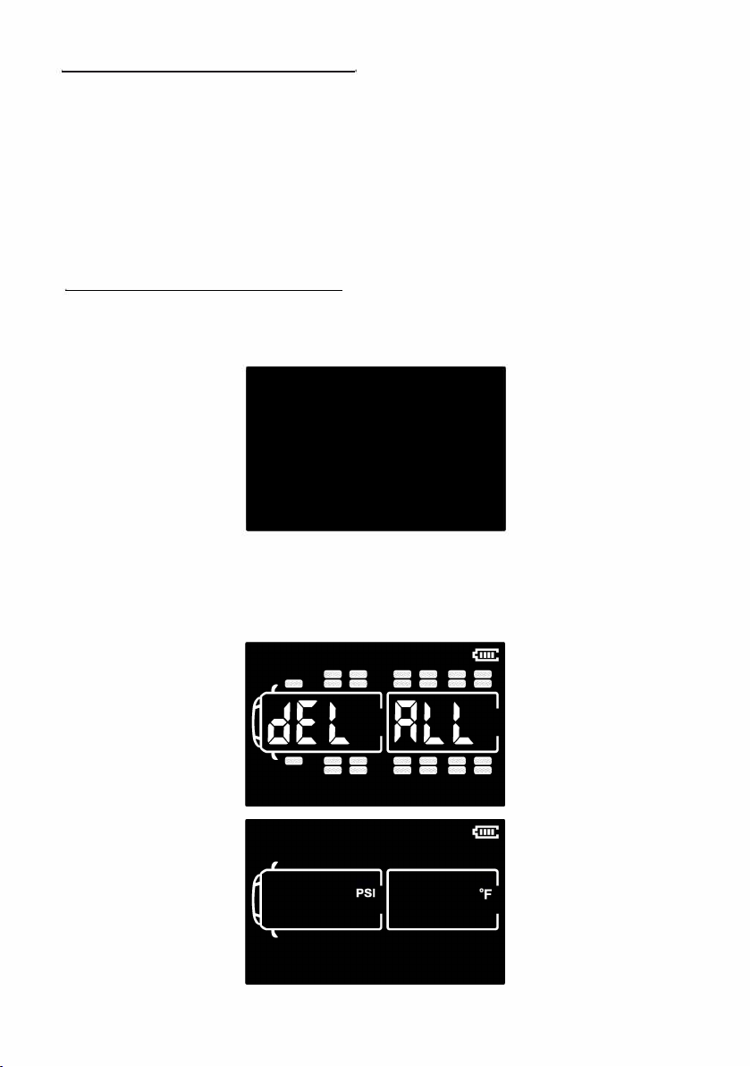
DELETING ALL SENSORS ID
1. In operating mode, press and hold the CODE button for 3 seconds,
release it after the beep to enter the coding mode. A flashing tire
icon and ID code are displayed.
oci
2. Press and hold the TRACTOR button for 3 seconds, release after
a long beep, all the sensors ID are deleted. To return to operating
mode, press and hold the CODE button for 3 seconds until you
hear a beep.
------------- 15 -------------

OTHER FUNCTIONS
Typical Scrolling Display During normal operation, the monitor scrolls through
and shows the tires one by one for approximately 6 seconds. A single audible
chirp will be issued if the monitor does not receive one of the sensors data for
more than 30 minutes. You can manually scroll through and select the tire by
pressing the+ or button. A manually selected tire will be displayed for 10
seconds. Backlight and Motion Sensor The monitor has a built-in light and motion
sensor. The backlight turns on when it detects the vehicle is in motion and when
it is dark enough or you may wave your hand in front of
the monitor to activate it.
Press any button hold the + button for 3 seconds. The monitor will enter sleep
mode to conserve battery life if the motion sensor does not detect motion for 15
minutes. It will come back to operating mode when the vehicle is moving again
or other motion.
Backlight and Motion Sensor
The monitor has a built-in light and motion sensor. The backlight turns on
when it detects the vehicle is in motion and when it is dark enough or you
may wave your hand in front of the monitor to activate it. Press any button
on the monitor to turn on the backlight manually; to turn it off, press and
hold the + button for 3 seconds.
The monitor will enter sleep mode to conserve battery life if
the motion
sensor does not detect motion for 15 minutes. It will come back to operating
mode when it detects the vehicle is moving again or other motion.
To drop the image of
the towing vehicle from the screen press and release the
LINK and+ key at the same time. To display it back on the screen press and
release the LINK and+ key at the same time again. (This will allow you to use the
system in your towed when not connected to the coach.)
To drop the image of
the towed vehicle/trailer from the screen press and
release the LINK and -key at the same time. To display it back on the screen
press and release the LINK and key at the same time again.
16 --------------

Charging the Monitor
The lithium-ion battery inside the monitor, when fully charged is capable of
running for up to 60 hours between charges. When the battery symbol bars
are gone, or the box appears, a recharge is required.
OUT OF PARAMETER ALERTS
The system cycles from tire to tire every 6 seconds, if there is a significant
change in pressure or temperature in this cycle it will transmit it to the
monitor. If not, it will maintain the reading and transmit a full update every 5
minutes. This is to conserve the sensor battery. If any reading goes out ofthe
pre-defined parameter, the system will interrupt the cycling and give you a
real-time alert; you will notice three things:
1. An audible alarm;
2. The red light on the lower right side of the monitor will flash;
3. The corresponding tire on the monitor will flash, and a text message of
what is wrong will appear on the screen.
Press any button to switch the alarm off. However, the red light will not be turned off
until the correct pressure, and temperature settings are restored to within range.
When the sensor detects High-Pressure
in a tire, it will send an alert to the monitor
immediately. HIGH-PRESSURE will show
on the LCD and the corresponding tire
icon will flash. The audible alarm will be on
together with the flashing red light. Press
any button to turn off the alarm. However
the flashing red light and text will continue
until the problem is corrected.
Low-Pressure Alert
When the sensor detects Low-Pressure in
a tire, it will send an alert to the monitor
immediately. LOW-PRESSURE will show
on the LCD and the corresponding tire
icon will flash. The audible alarm will be on
together with the flashing red light. Press
any button to turn off the alarm. However
the flashing red light and text will continue
until the problem is corrected.
------------- 17 -------------

High-Temperature Alert
When the sensor detects High-Temperature
in a tire, it will send an alert to the monitor
immediately. TEMP HIGH will show on
the LCD, and the corresponding tire icon
will flash. The audible alarm will be on
together with the flashing red light. Press
any button to turn off the alarm. However,
the flashing red light and text will continue
until the problem is corrected.
Fast Leak Alert
When the sensor detects a rapid air loss in
a tire, it will send an alert to the monitor
immediately. FAST LEAKAGE* will show
on the LCD, and the corresponding tire
icon will flash. The audible alarm will be on
together with the flashing red light. Press
any button to turn off the alarm. However,
the flashing red light and text will continue
until the problem is corrected.
Sensor Low Battery Alert
When the sensor battery becomes
low, it will send an alert to the monitor
immediately. The LOW BATTERY ICON will
show on the LCD, and the corresponding
tire icon will flash. The audible alarm will
be on together with the flashing red light.
Press any button to turn off the alarm.
However, the flashing red light and icon will
continue until the problem is corrected.
Notes:
* Fast Leak Alert Parameter is preset by the factory to alert when an air loss of Z25 psi per minute occurs.
** If a sensor battery dies while in storage or the system is off you will not get an alarm on the monitor when
you turn it on. If you are not getting a reading check the sensor battery.
18 --------------
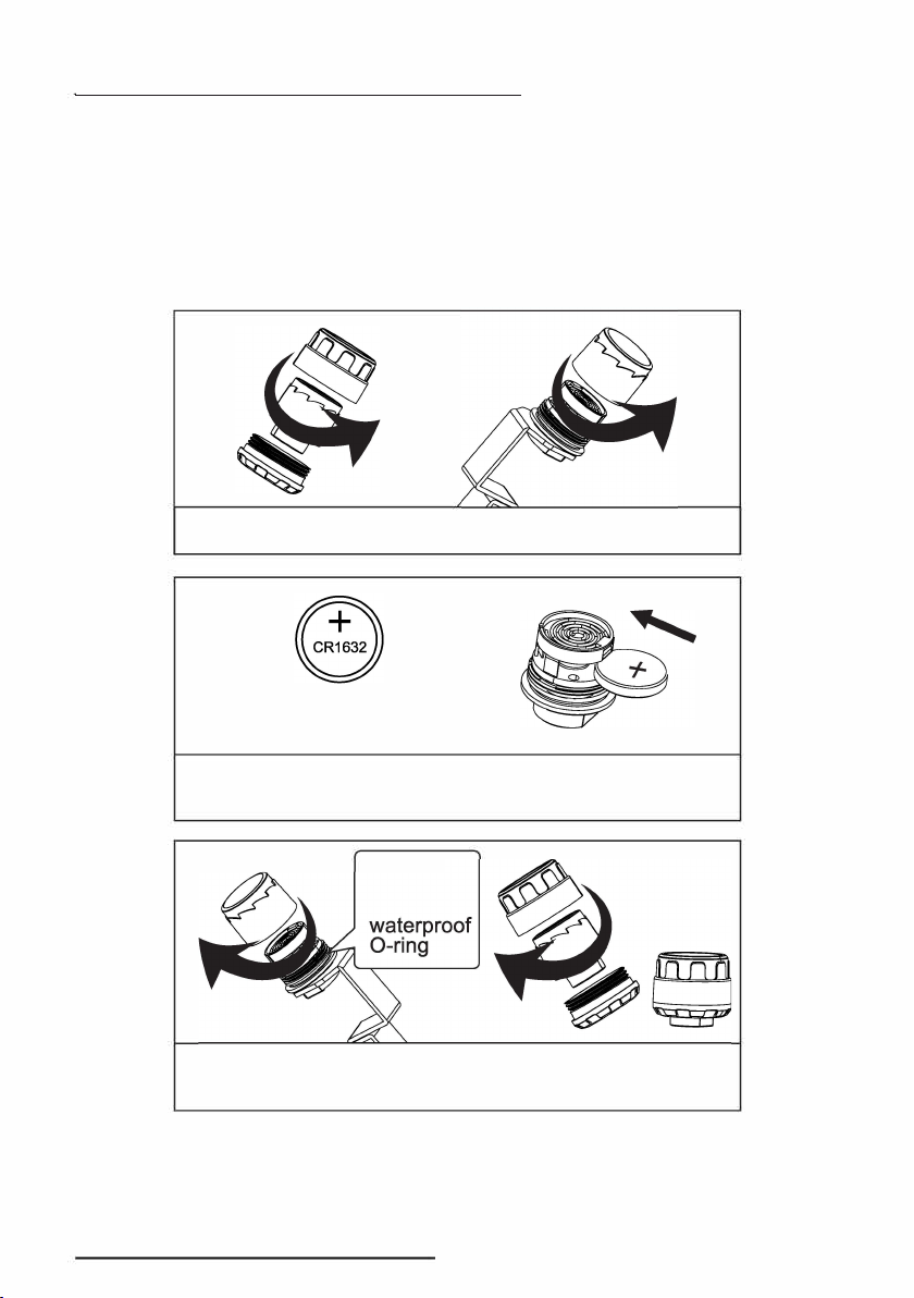
Replacing Anti-Theft Sensor Battery
When you here the low battery tweet sound coming from the monitor it is time
to replace the battery.
Replace with a CR1632 battery, which operates at -40°F to 176 °F. These can
be purchased at many hardware stores, Radio Shack or large Wal mart
on-line at either eBay, Amazon.com or on our site www.eezrvproducts.com.
NOTE: If
a
sensor stops transmitting the first thing you want to check is the
sensor battery. Remove the battery and check it with
a
voltmeter, it should read
3.2V. Anything below 2.9V should be replaced.
Open the sensor cap anti-clockwise.
"+"
CR 1632 Lithium battery
Replace a new CR1632 battery and make sure
positive pole upside.
0
Check the waterproof O-ring, replace a new one if it
is broken.
19 ---------------
This manual suits for next models
1
Table of contents
Other EEZ RV Automobile Accessories manuals

Popular Automobile Accessories manuals by other brands

Westin
Westin 46-23785 instructions

BMW
BMW 82 44 0 007 417 installation instructions

IAME
IAME Parilla X30 Assembly instructions and user's manual

Yakima
Yakima LoadRanger 16s manual

Guerrilla Exhaust
Guerrilla Exhaust Guerrilla Bypass installation manual

iKeyless
iKeyless SolidKeysUSA FOBIK 300-0388 Pairing Instructions


Ocular
Ocular LTE Plus installation guide

Prorack
Prorack K388 Fitting instructions

dirna Bergstrom
dirna Bergstrom Bycool Green Line Compact 3.0 Mounting instructions

Fortin Electronic Systems
Fortin Electronic Systems PATS 2 installation guide

Directed
Directed GM11 installation guide

Phonocar
Phonocar 05965 installation instructions