Diode Dynamics SS5 User manual
Other Diode Dynamics Automobile Accessories manuals
Diode Dynamics
Diode Dynamics DD0438 User manual
Diode Dynamics
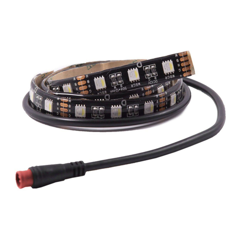
Diode Dynamics RGBW LED Board User manual
Diode Dynamics
Diode Dynamics Stage Series User manual
Diode Dynamics
Diode Dynamics DD5002 User manual
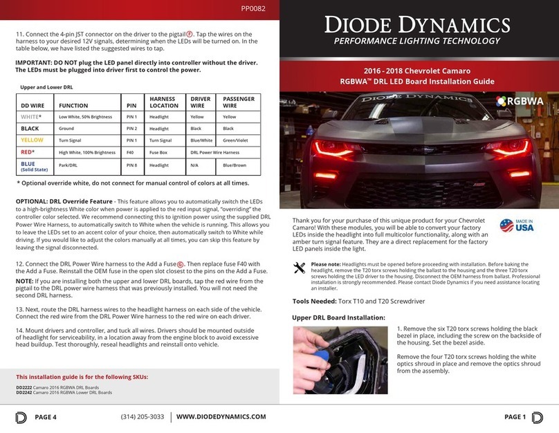
Diode Dynamics
Diode Dynamics RGBWA DRL DD2222 User manual
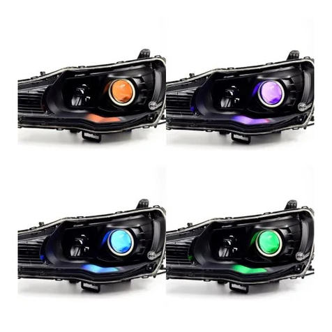
Diode Dynamics
Diode Dynamics Demon Eyes User manual
Diode Dynamics
Diode Dynamics SS18 Bracket Kit User manual
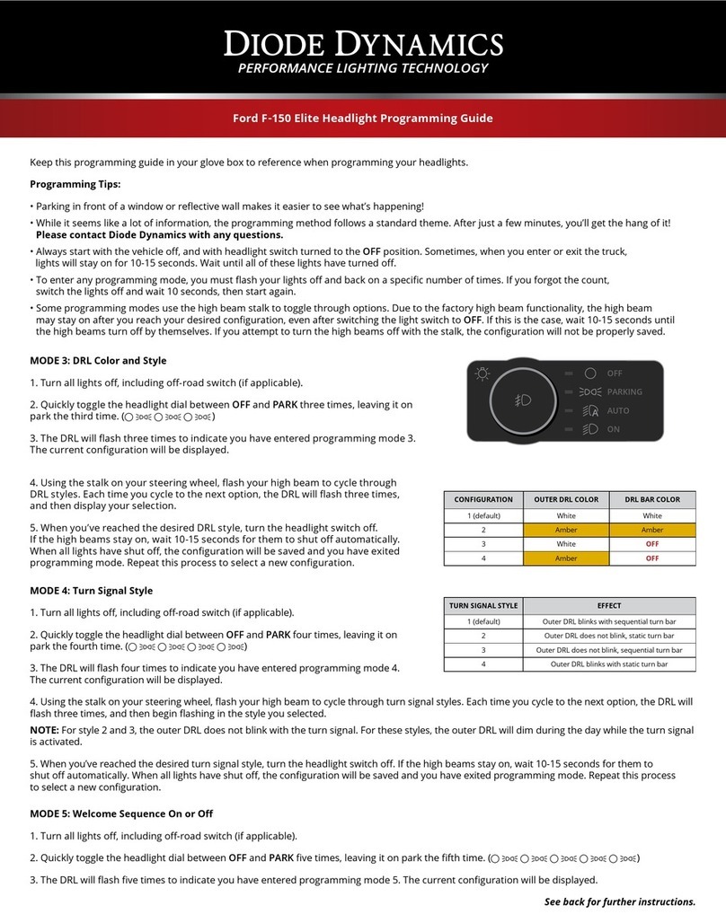
Diode Dynamics
Diode Dynamics DD5167 Operating instructions
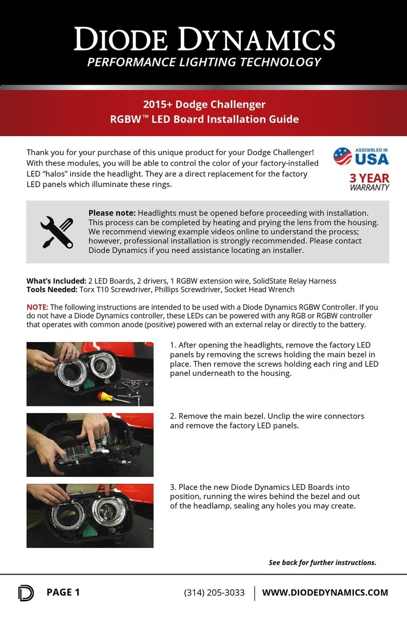
Diode Dynamics
Diode Dynamics RGBW DD2163 User manual

Diode Dynamics
Diode Dynamics Stage Series SS3 User manual

Diode Dynamics
Diode Dynamics STAGE Series User manual
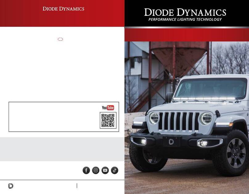
Diode Dynamics
Diode Dynamics DD6090 User manual
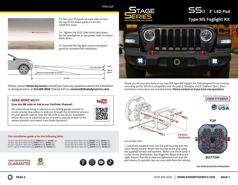
Diode Dynamics
Diode Dynamics DD7059 User manual
Diode Dynamics
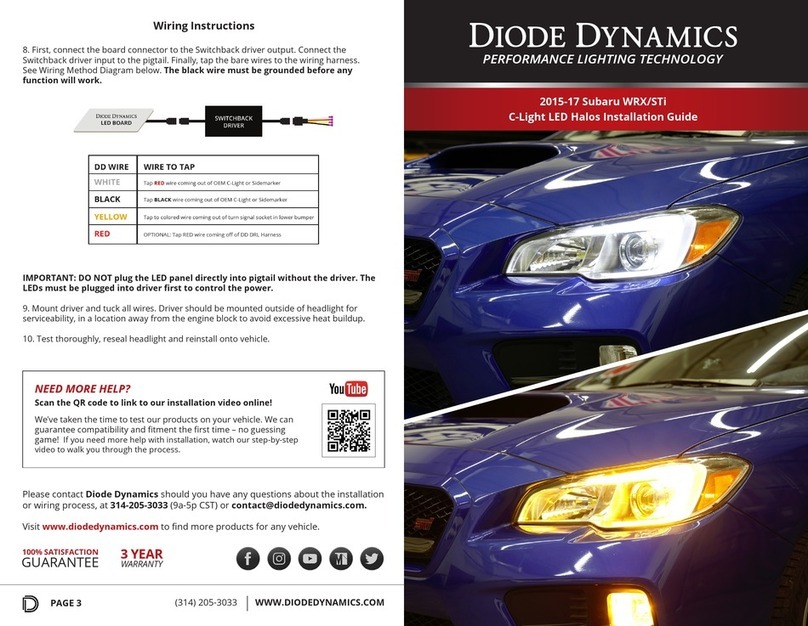
Diode Dynamics C-Light LED Halos User manual
Diode Dynamics
Diode Dynamics DD0442 User manual
Diode Dynamics
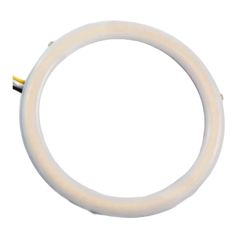
Diode Dynamics HD Halo User manual

Diode Dynamics
Diode Dynamics STAGE Series User manual
Popular Automobile Accessories manuals by other brands
rough country
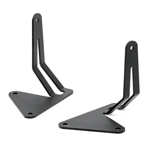
rough country 92705360 manual
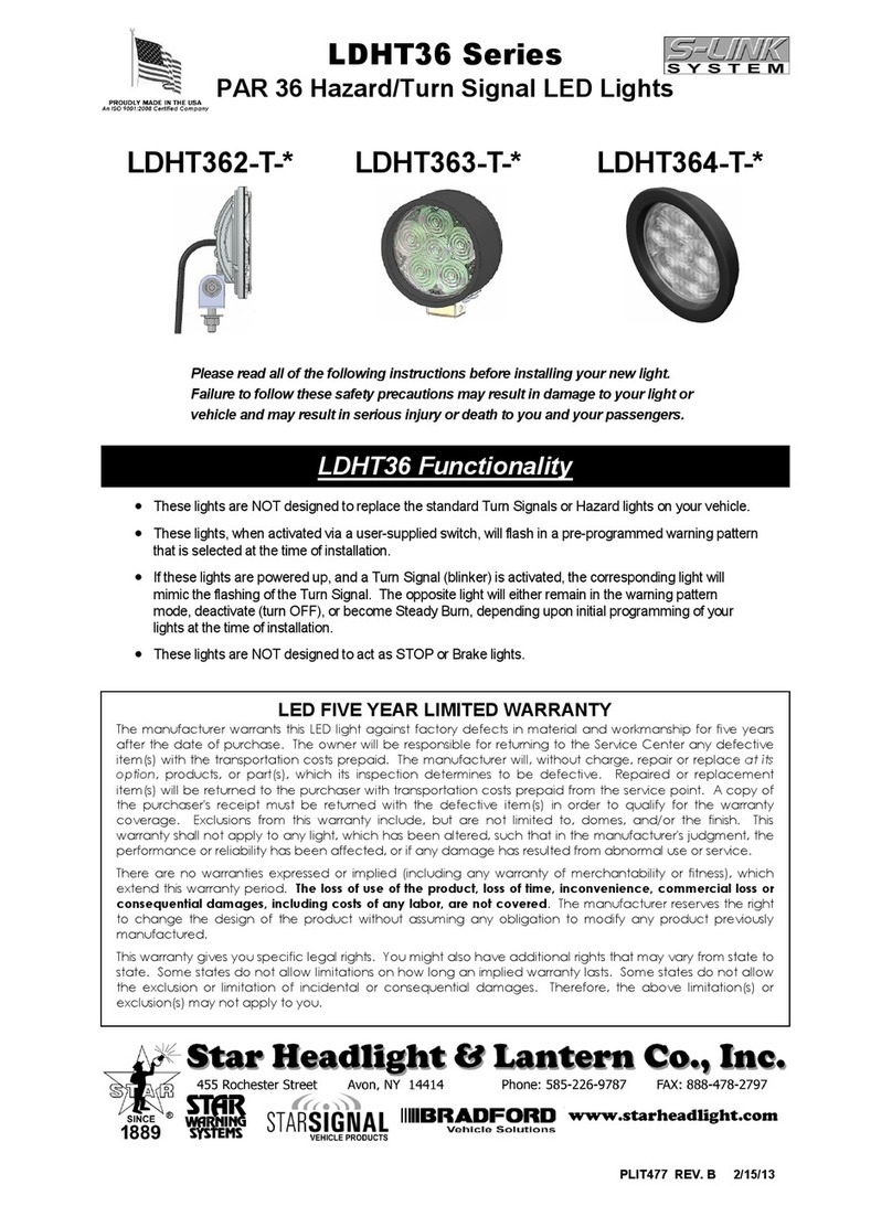
Star Headlight & Lantern
Star Headlight & Lantern LDHT36 Series manual
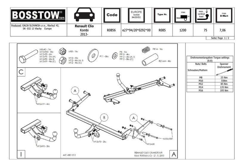
BOSSTOW
BOSSTOW R0856 manual
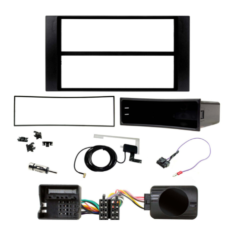
TOP VEHICLE TECH
TOP VEHICLE TECH GR3FORD4 installation manual
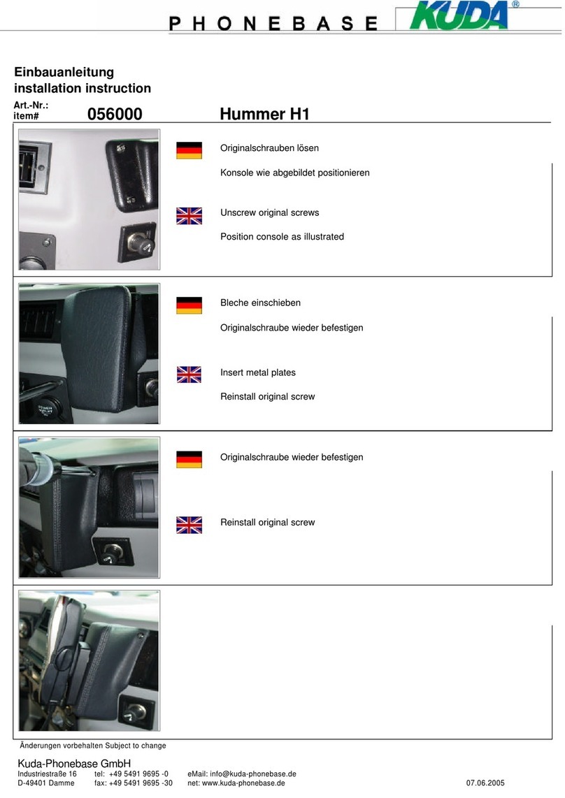
Kuda-Phonebase
Kuda-Phonebase 056000 Installation instruction
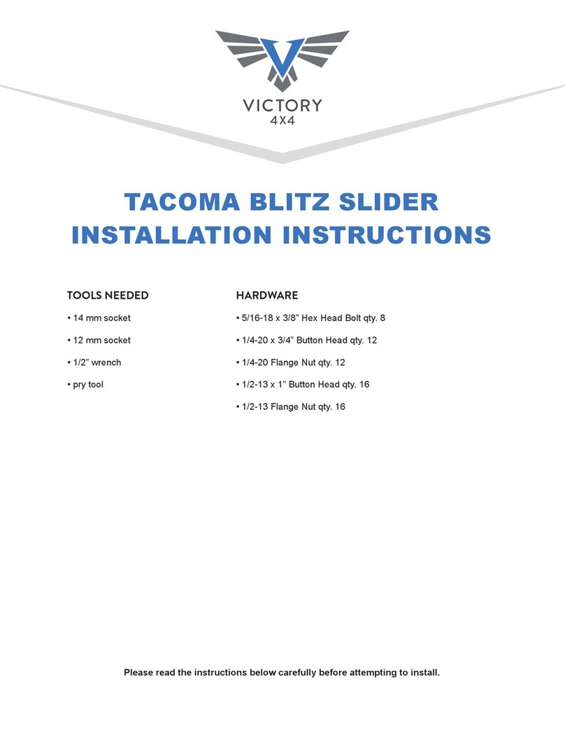
Victory 4x4
Victory 4x4 VT23SL-BL installation instructions
Bury technologies
Bury technologies ISO cable harness Quick user guide

Kenwood
Kenwood KCA-R200 instruction manual
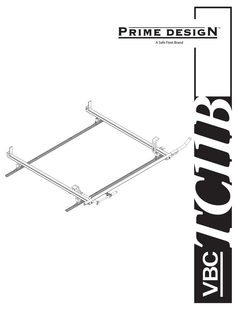
Safe Fleet
Safe Fleet PRIME DESIGN VBC-TC11B manual

LSD-Doors
LSD-Doors 50080028 installation instructions
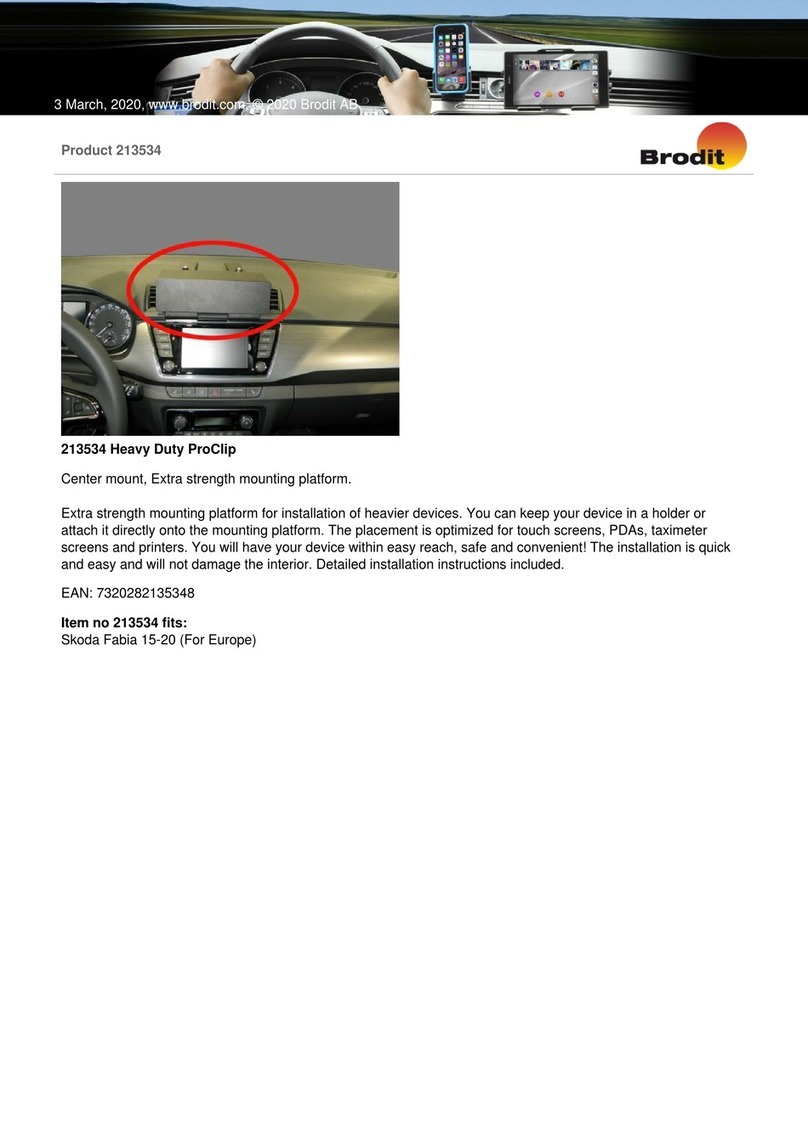
Brodit
Brodit Heavy Duty ProClip installation instructions

STO N SHO
STO N SHO SNS 41 Installation procedures


