EEZ BB3 User manual

EEZ BB3 two channel kit assembly instructions
Last modified: 2021-06-12
Read me first
Introduction
Instructions presented in this document are related to BB3 – Two Channel (Full) kit offered through a
crowdfunding campaign.
The EEZ BB3 kit is not an end-user product. As such, it has not een su jected to any conformance
testing, and it may not comply with some or any technical or legal requirement that are applica le to fin-
ished products including, without limitation, directives regarding electromagnetic compati ility and recy-
cling for instance (WEEE, FCC, CE or UL). Assem ling and using the EEZ BB3 requires an under-
standing of electronic circuits and asic computer programming skills.
f you need assistance, please contact us using this form or join us on our Discord server (invitation) or
post your problem on the EEVblog forum here. Or, feel free to open a New issue on GitHub here, but
please check first to see whether a similar issue already exists).
The only tool required for the kit mechanical assem ly is a medium Phillips head screwdriver. Of
course, a multimeter for checking the wiring and voltage at a few points during assem ly is recom-
mended.
Before you start
We made our est effort to make your EEZ BB3 kit complete and functional. However, please note that
due to limited resources, the kit is not completely and thoroughly tested. Basic tests were performed on
the core and power modules and the cooling fan.
Modules are tested on our “test ed”, ut not using a wire harness, with the AC/DC modules that come
with your kit. Therefore, it’s highly recommended that you check visually, mechanically and with an
ohmmeter that ca les are properly assem led efore you proceed with final assem ly (consult the Wire
harness section).
The asic testing covered communication over Ethernet, fan control, power control, touchscreen func-
tionality, eeper, TFT display and output voltage and current programming over the full range (i.e. up to
40 V and 5 A with connected load). The AC/DC modules are capa le of working with oth 115 and
230 VAC.
Kit version identification
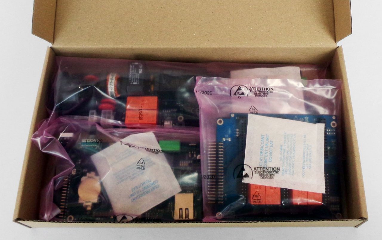
Starting in April 2021, the BB3 kit with new versions of the modules is on sale. They are most easily
recognized y the lue color of the PCBs (Fig. 3) as opposed to the crowdfunding version which has
green PCBs. The kit version with the new modules for simplicity will e listed elow according to the
MCU module version num er which is r3B3 (the previous version is r2B4).
If you own the r3B3 version, consider the following:
•The SDcard comes already mounted on the MCU module. It is recommended that you remove
the SDcard efore mounting the front panel (Fig. 12, 13, 14).
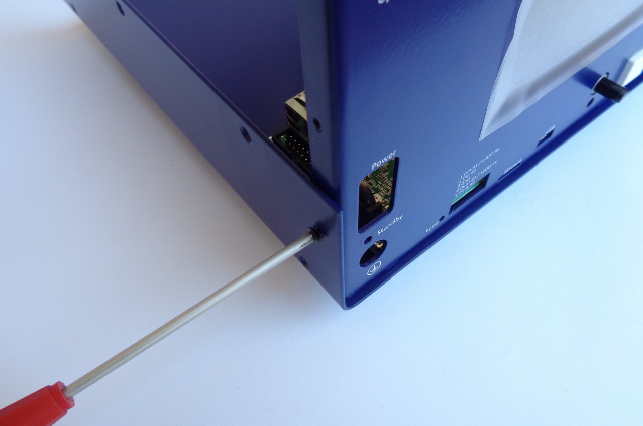
•The holes on the front panel for the Stand y LED and PE terminal can e too tight, which can
make it difficult to mount the front panel ecause the LED indicator can move in the process
from the center. If this happens carefully from the ack of the front panel with a screwdriver
return the LED indicator to sit in its hole.
•Your MCU module may have come with v1.6 firmware installed. If this is the case you will need
to update it to v1.6.1 or later otherwise working with power modules (DCP and DCM) will not e
possi le (see resolved issue #172).
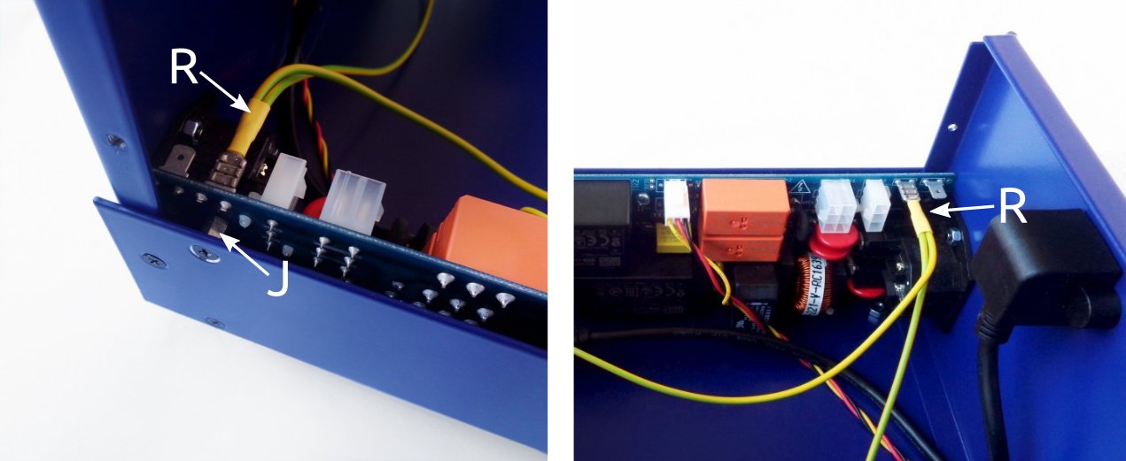
•The AUX-PS module (r3B5) is missing one mounting hole (a ove the AC inlet). Therefore for PE
connection to the chassis a separate wire is used (Item R, Fig. 5)
•Top cover (Item 1, Fig. 1) has two additional holes for etter fixation to the front and ack panel.
1

EEZ BB3 two channel kit assembly instructions
Field report update (r2B4 version)
A large num er of ackers have already successfully completed their EEZ BB3 kit. In a small num er of
cases, they encountered issues with the supplied parts. The issues seen are:
•The 16-pin IDC ca le may e faulty (Item F, Fig. 4). The ca le pro lem can e detected y
visual inspection, and if it is connected etween the AUX-PS and the MCU module, the MCU
module will not work (nothing will appear on the display, no tone will e heard). If you don't want
to wait for replacement use D89116-0031HK-3365/16-D-3 availa le on Digi-key.
•Missing M3 threads on 2 of the 4 holes on the Mean Well AC/DC converter mounting frame
(Item 5, Fig. 1)
•One Hexagonal M3×6 mm metal spacers (Item J, Fig. 4) may e missing
•One or more M3×5 mm countersunk screws (Item M, Fig. 4) may e missing
•You can find excess M3×4 mm screws (Item L, Fig. 4)
•TFT display on enclosure front panel (Item 3, Fig. 1) came with roken glass
•Important discovery that may affect backers that has AUX- S module r3B3 (green CB):
#108.
Feel free to contact us if you notice any defect that we can arrange a replacement.
Kit assembly steps
•Package content
•Plastic ags content
•Bottom plate
•Installing MCU and BP3C
•Connecting TFT display
•Front panel mounting
•Installing AUX-PS module
•Rear panel mounting and ca le connection
•First power up and installation of power modules
•User manual and firmware update
1. ackage content
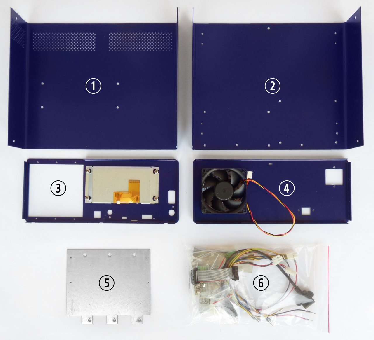
The BB3 kit consists of the following parts, as shown in Fig. 1 and Fig. 2:
Item Description
1 Pre-drilled enclosure top cover
2 Pre-drilled enclosure ottom plate
3 Enclosure front panel with mounted 4.3” TFT touch-screen color display
4 Enclosure rear panel with mounted Ø80 mm cooling fan
5 Mean Well AC/DC converter mounting frame
6 Plastic ag with wire harness and miscellaneous mounting parts
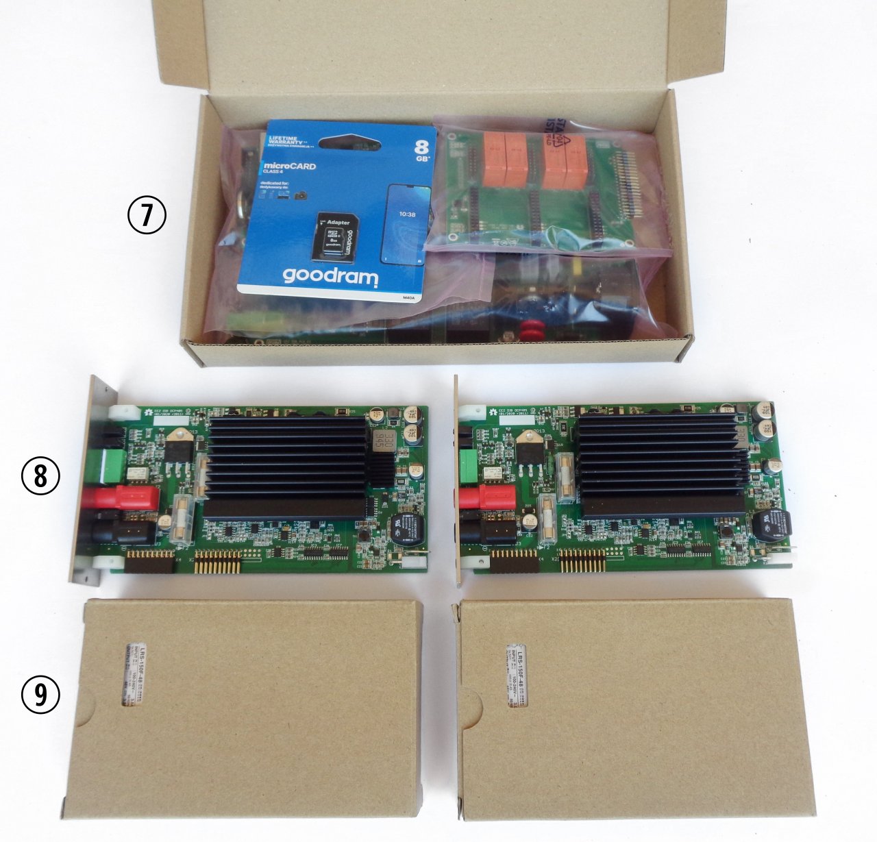
7 Core modules (AUX-PS, MCU and BP3C) and micro SD card
8 DCP405 power module ×2
9 Mean Well 48 VDC AC/DC converter ×2
Please note that an AC power cord is not included with this kit.
2


EEZ BB3 two channel kit assembly instructions
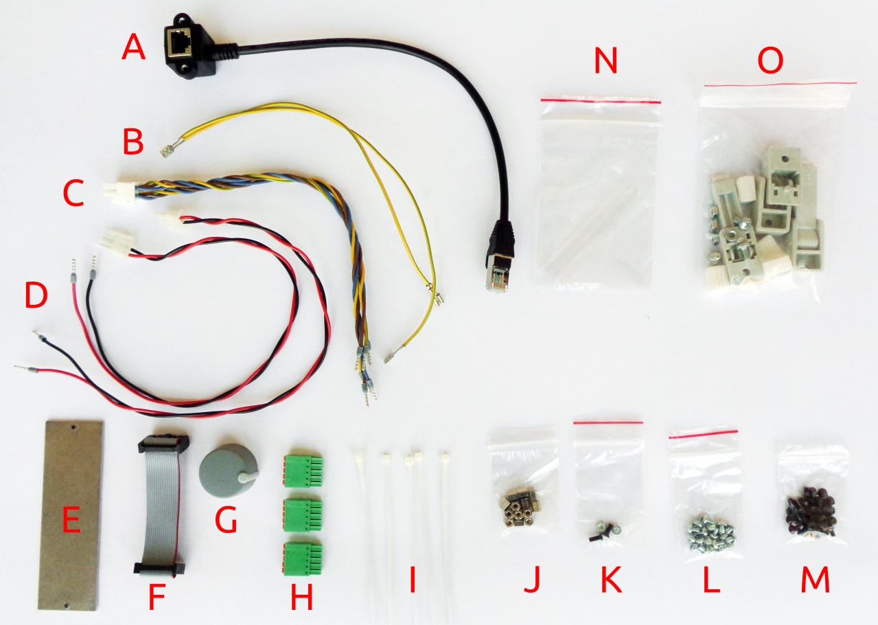
2. lastic bag contents
Before start assem ly please take some time to check that the contents of the plastic ag (item 6) in-
clude everything listed elow. Also familiarize yourself with the tem naming that will e used in the rest
of the document.
Item Description
A Ethernet patch ca le
B Dual power module PE (Protective Earth) ca le
C Dual AC/DC power module AC input ca le
5
Fig. 4: Plastic bag content
Fig. 3: r3B3 base modules (SD card is already installed on the MCU module)

EEZ BB3 two channel kit assembly instructions
D Power module DC input ca le
E Blind module front panel
F 16-pin IDC flat ca le
G Encoder kno
H 5-pin push-in connectors
I Ca le ties ×6
J Hexagonal M3×6 mm metal spacers ×13
K Mounting set for AC power inlet
L M3×4 mm screws ×13
M M3×5 mm countersunk screws ×40
N Mean Well terminal covers
O Enclosure feet kit
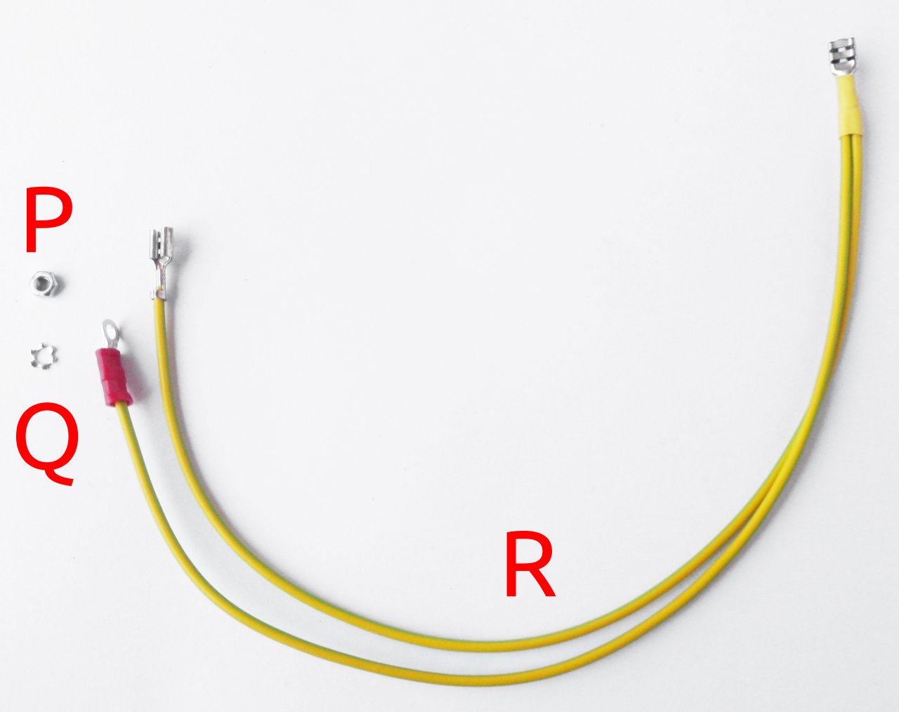
Additionally, the r3B3 version comes with the following PE mounting kit:
Item Description
P Ethernet patch ca le
Q Dual power module PE (Protective Earth) ca le
R Dual PE (Protective Earth) ca le for display
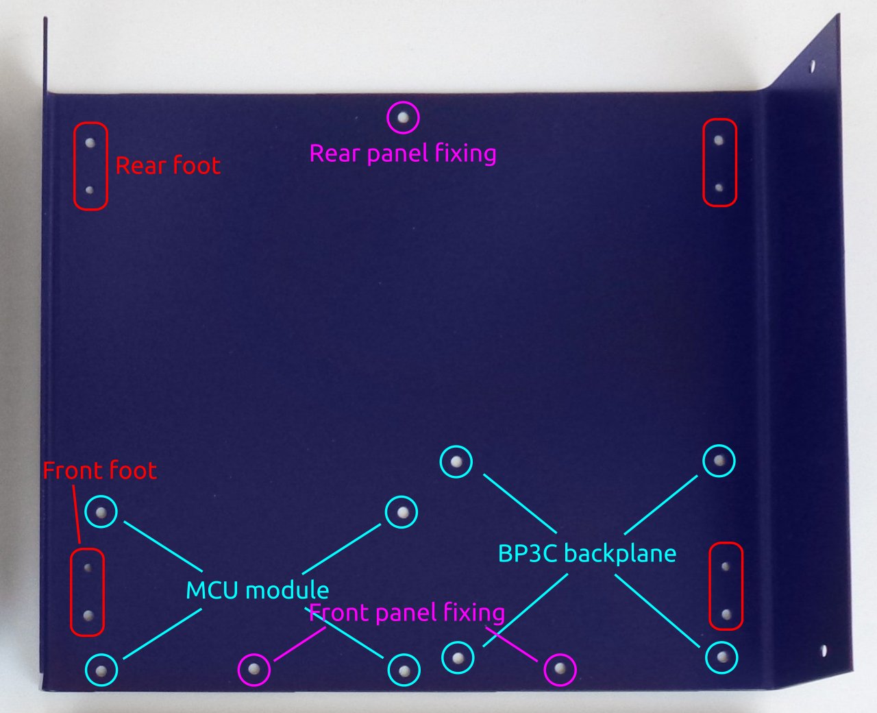
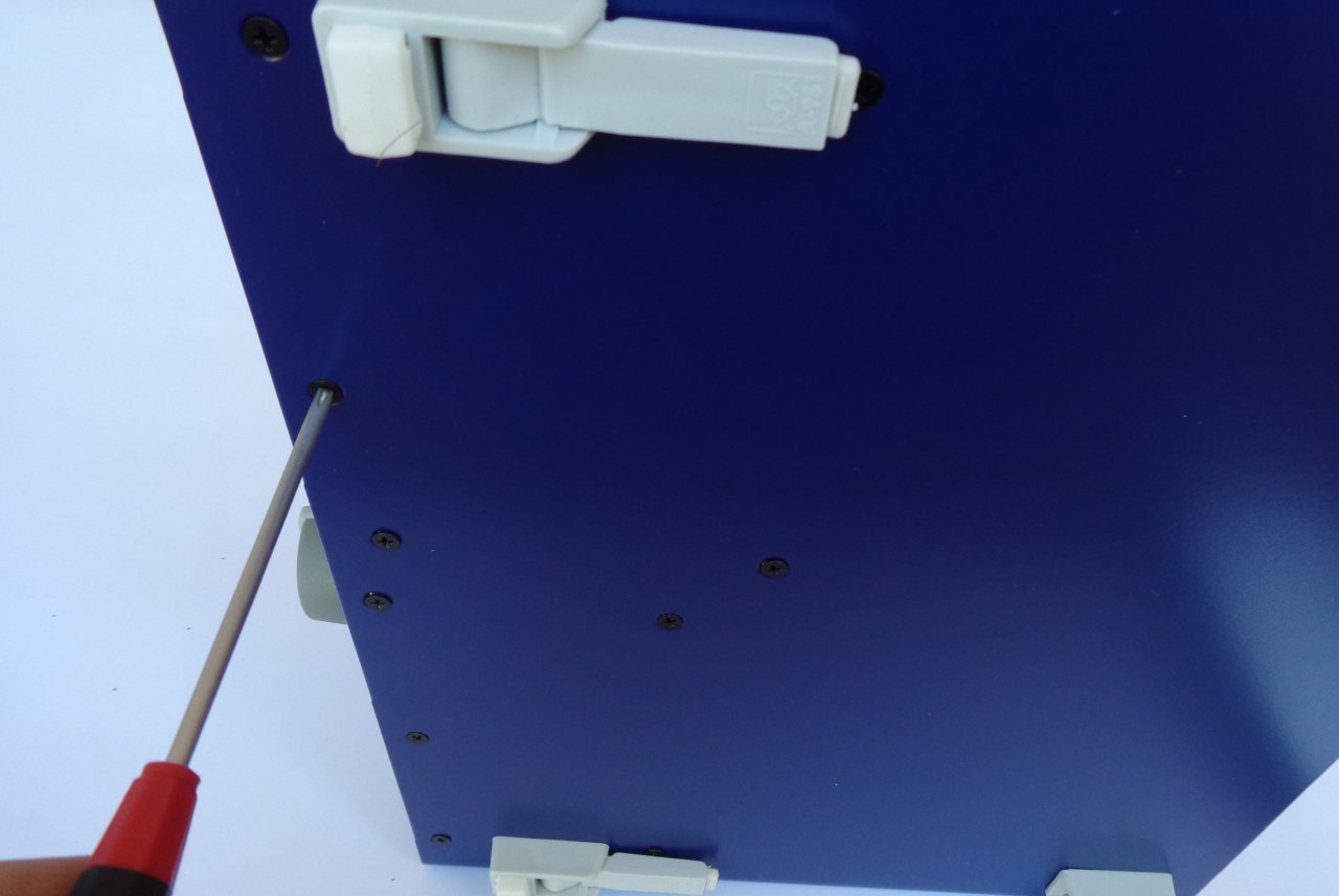
3. Bottom plate
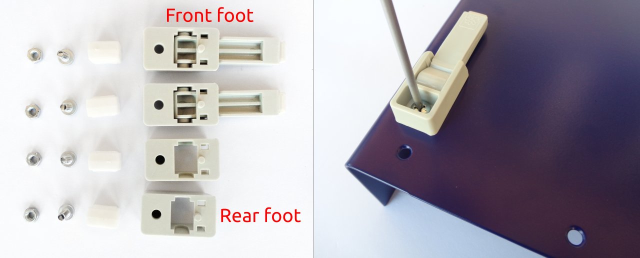
As a first step, mount the plastic feet. Identify the foot holes on the ottom plate (Fig. 6.) and unpack the
content of the ag with the foot parts (item O, Fig. 4.). The front feet come with an extended part that,
when mounted and folded out, can set the enclosure at an angle.
6
Fig. 5: r3B3 PE mounting kit


EEZ BB3 two channel kit assembly instructions
Rubber inserts inserted to different depths may cause the bottom plate not to be leveled. f you wish to
correct the leveling now, press carefully along the ends of the bottom panel until a satisfactory result is
obtained. The final leveling can also be done after all the components have been installed and the top
panel mounted. This is the recommended method because it is less likely to cause the bottom plate to
deform during the leveling process.
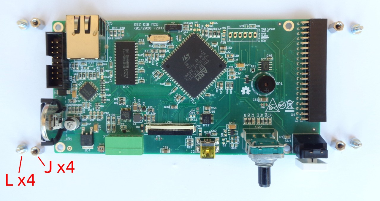
4. Installing MCU and B 3C
Remove the MCU module from the package. Since it comes with a attery installed, take care to avoid
short circuits from placing it on a conductive surface. Fig. 9 shows the parts (referenced y the la els in
Fig. 4) required for mounting this module.
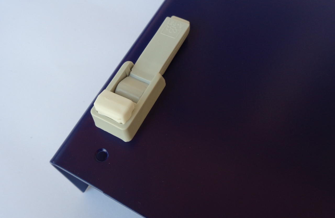
8
Fig. 8: Front foot mounting completed

EEZ BB3 two channel kit assembly instructions
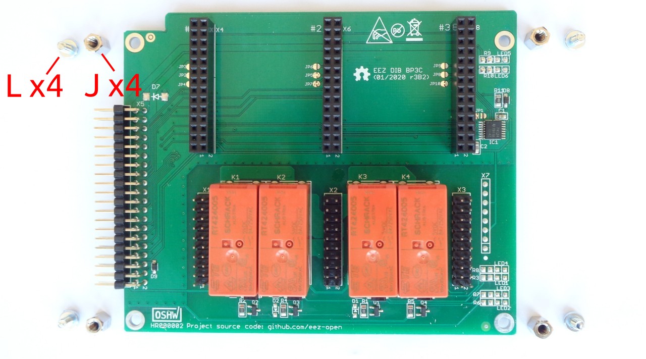
Attach the hexagonal metal spacers (J) using screws (L) to the four holes at the corners of the module.
Repeat the same procedure on the BP3C ackplane shown in Fig. 10.
Carefully connect the modules together (40-pin X1 socket on MCU module side and X5 header on
BP3C side). You can now proceed with mounting the module to the ottom panel using screws (item M
in Fig. 4) in the positions shown in Fig. 6.
Do not completely tighten these screws before installing the front panel.
9
Fig. 9: MCU module r2B4 with mounting parts
Fig. 10: BP3C backplane with mounting parts

EEZ BB3 two channel kit assembly instructions
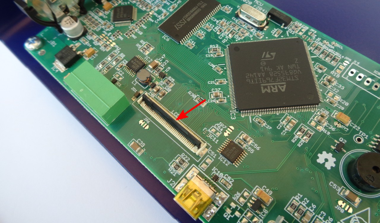
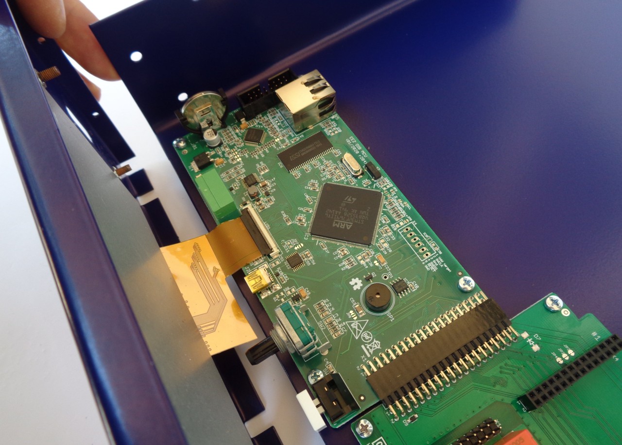
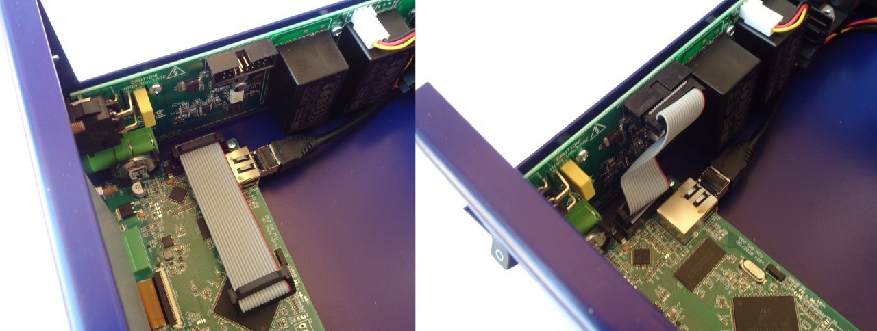
5. Connecting TFT display
In order to mount the front panel to the ottom panel, it will e necessary to connect the TFT display to
the MCU module, first. This is the most delicate operation in the entire EEZ BB3 assem ly procedure,
so it requires extra care.
First, identify the connector position on the MCU module and carefully place the lack plastic lever in
the up position (Fig. 11) to allow the display flat flexi le ca le (FFC) to enter smoothly.
Do not power on the MCU module without the display connected or with a loosely connected flexible
display cable. Doing so may damage the power supply of the display backlight located on the MCU
module.
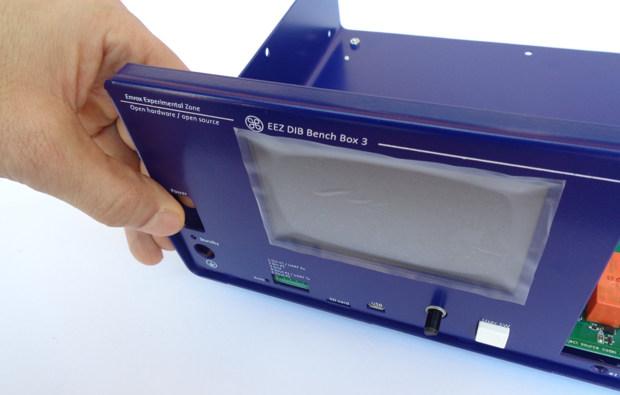
6. Front panel mounting
Carefully end the display ca le so that it is in line with the FFC connector and slowly insert it (Fig. 12).
When the flexi le display ca le is in place, lower the lack lever to lock the ca le (Fig. 13).
Do not force the flexible cable into the FFC connector as it may damage the cable and the connector.
10
Fig. 11: 40-pin FFC display connector


EEZ BB3 two channel kit assembly instructions
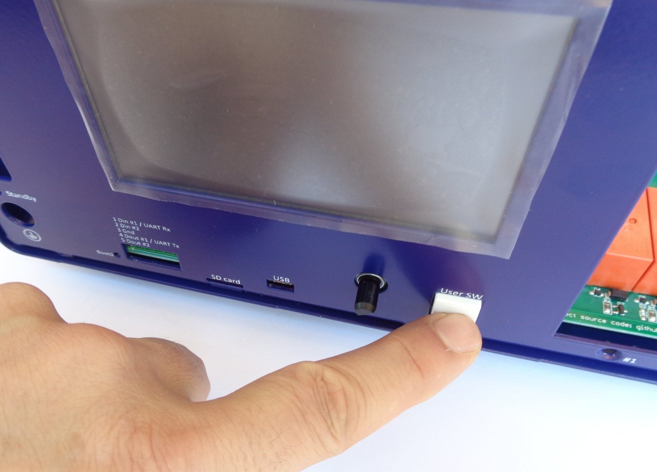
Before proceeding to fix the front panel to the ottom plate, check that the encoder shaft and user
switch are in place (Fig. 14). Additionally, check that the user switch is functional (Fig. 15); that it is not
pinched and that it can e depressed.
12
Fig. 13: 40-pin FFC connector in lock position


EEZ BB3 two channel kit assembly instructions
Fix the front panel to the ottom plate (Fig. 16) with two M3 screws (item M, Fig. 4.) in the positions
shown in Fig. 6. Continue the installation y fixing the front panel to the sides of the ottom plate with
another two M3 screws (item M, Fig. 4.) as shown in Fig. 17. Check again that the user switch is work-
ing and then tighten the 8 screws that hold the MCU and BP3C to the ottom plate.
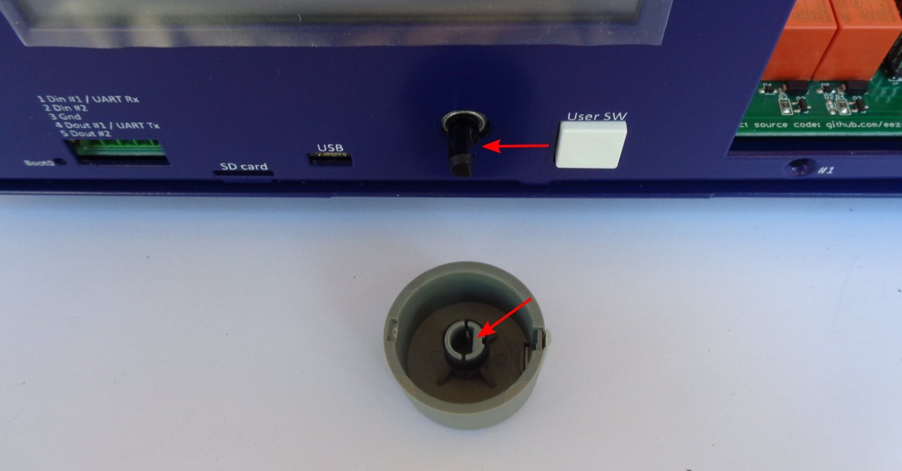
The encoder kno now can e mounted. Be sure to align the flat on the encoder shaft with the flat in the
encoder kno recess when mounting the kno (Fig. 18).
14
Fig. 17: Fixing the front panel from the side to the bottom plate
Fig. 18: Encoder knob before mounting

EEZ BB3 two channel kit assembly instructions
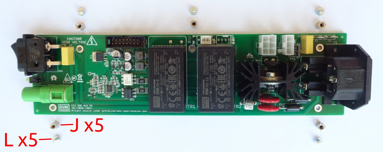
7. Installing AUX- S module
Remove the AUX-PS module from the package and attach the hexagonal metal spacers (J) using
screws (L) in the five holes of the module.
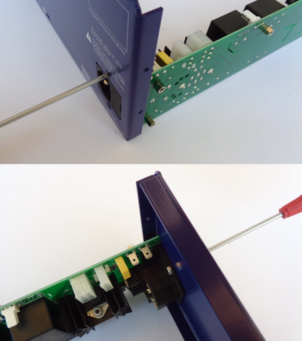
The AUX-PS module should e attached to the rear panel with two screws and nuts (contents of ag K
in Fig. 4). It is est to do this efore the AUX-PS is mounted on the ottom plate so that the nuts are
easier to access during mounting (Fig. 20).
15
Fig. 19: AUX-PS module with mounting parts

EEZ BB3 two channel kit assembly instructions
Continue to install the AUX-PS module y carefully inserting it from the ack, making sure that the
stand y LED and power switch locate in their holes in the front panel. When the AUX-PS module is in -
serted, secure it with 5 screws (item M, Fig. 4.) to the side of the ottom plate (Fig. 21).
16
Fig. 20: Mounting AUX-PS module to the rear panel

EEZ BB3 two channel kit assembly instructions
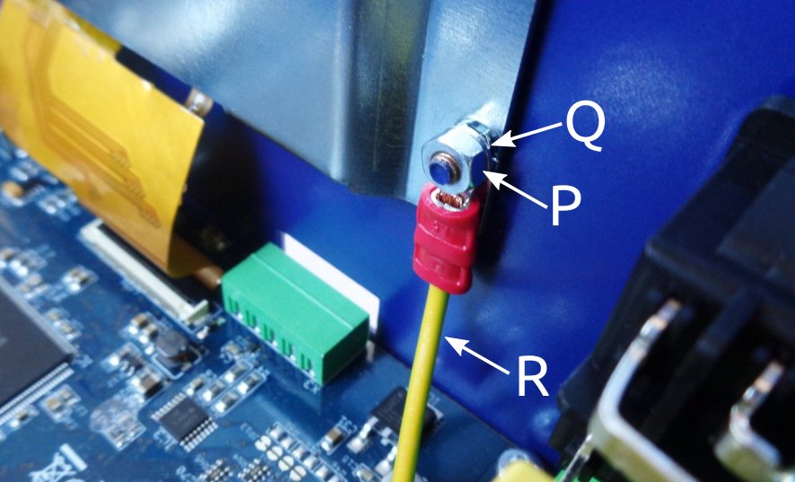
For the r3B3 version, you can now connect the PE wire (item R, Fig. 5) to the AUX-PS module and at-
tach one end to the TFT touchscreen display using item P and Q (Fig. 23). Note that item J in this case
is not fixed on the other side to the AUX-PS module, ut only touches it.
17
Fig. 21: Fixing the AUX-PS module on the bottom plate
Fig. 22: r3B3 enclosure PE wiring

EEZ BB3 two channel kit assembly instructions
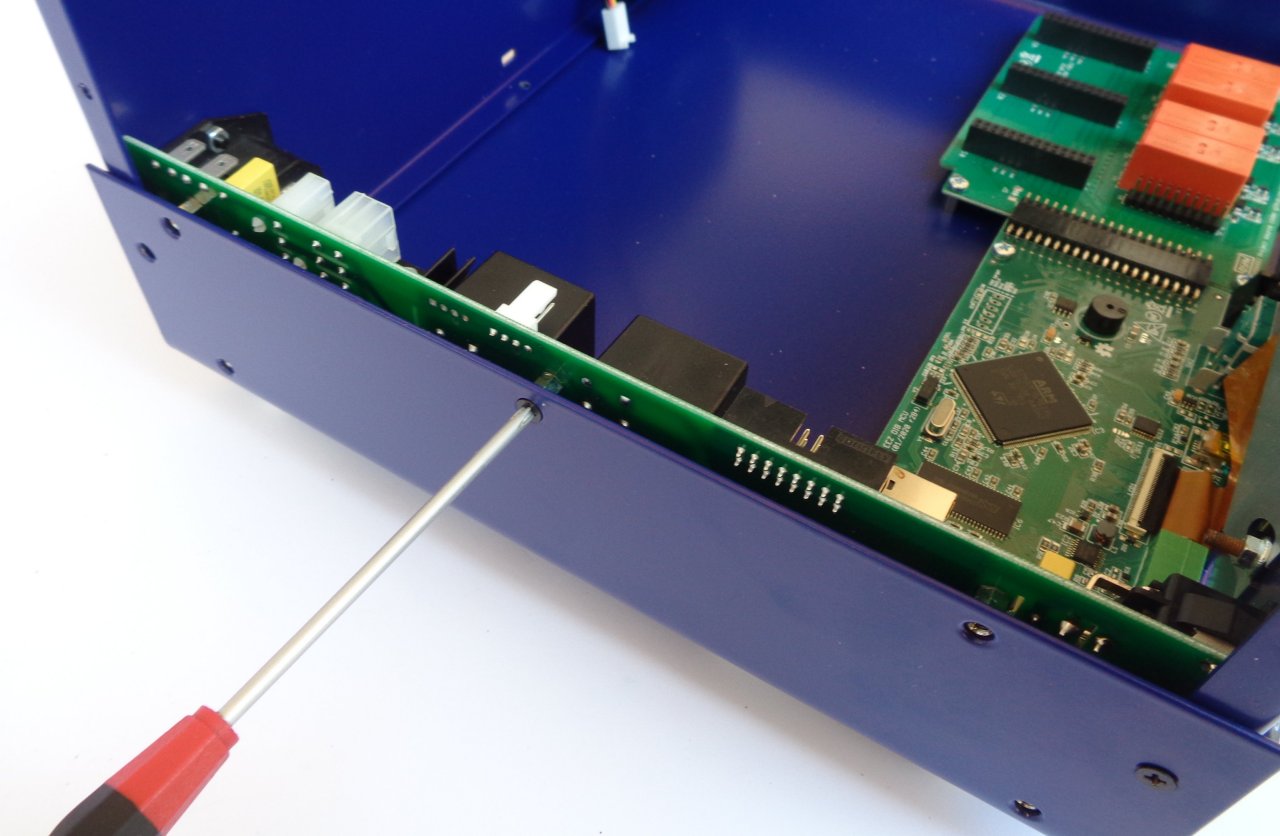
8. Rear panel mounting and cable connection
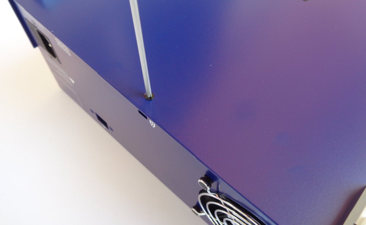
Attach the rear panel to the ottom plate. This will require three screws (item M, Fig. 4).
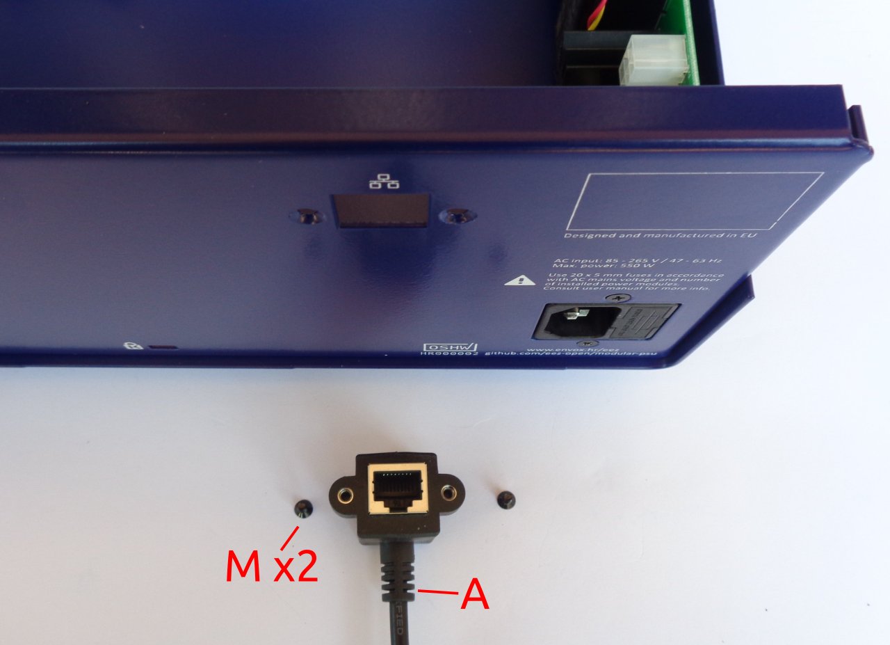
The Ethernet connection will require a patch ca le (item A, Fig. 4) and two screws (item M, Fig. 4) as
shown in Fig. 25.
18
Fig. 24: Rear panel mounting
Fig. 23: r3B3 PE wire attachment to the back of the display

EEZ BB3 two channel kit assembly instructions
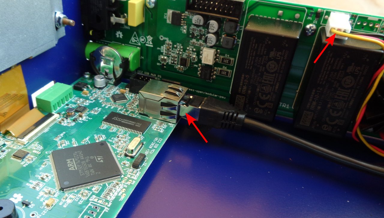
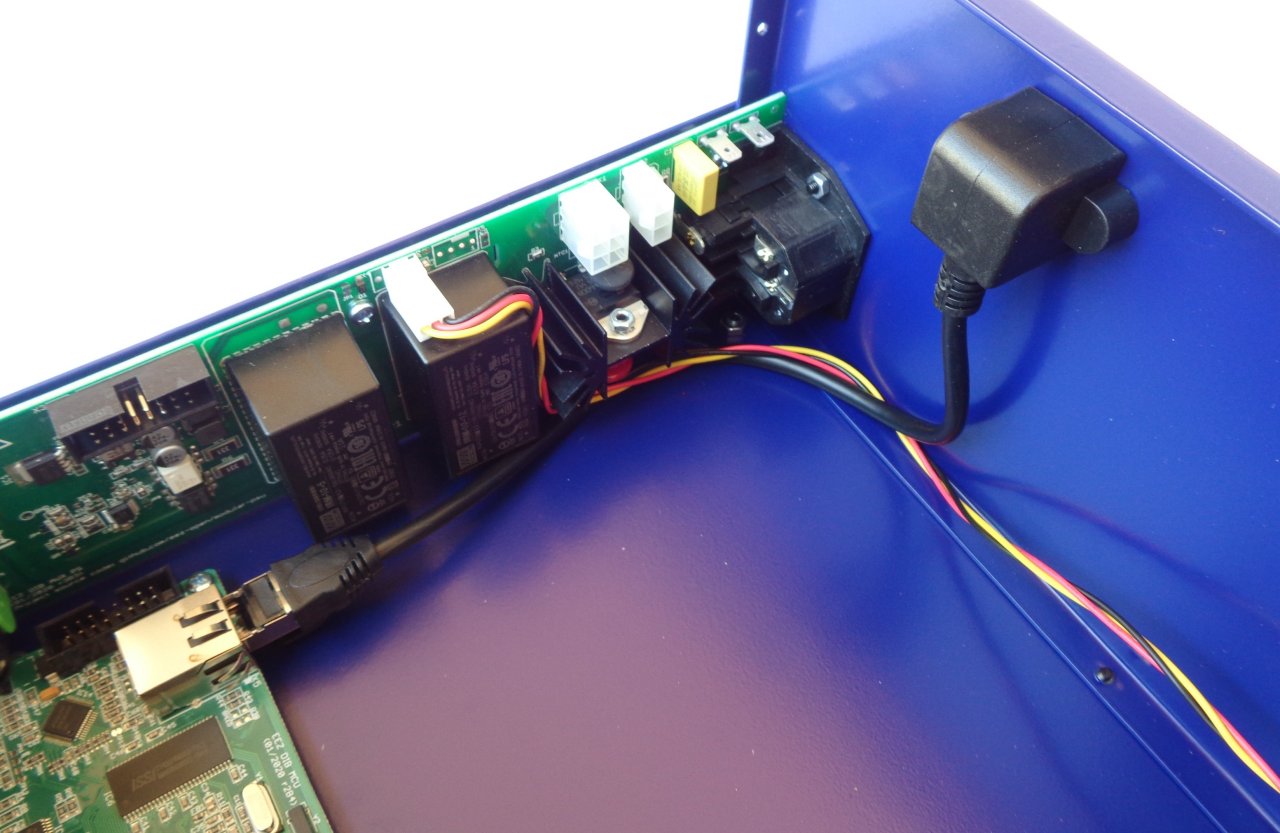
First, carefully insert the plug at one end of the Ethernet patch ca le into the MCU module and then se-
cure the other end to the rear panel. Now connect the cooling fan connector to the AUX-PS module as
shown in Fig. 26. Fig. 27 shows the mounted Ethernet patch ca le.
19
Fig. 25: Ethernet connection mounting parts
Fig. 26: Connecting Ethernet and cooling fan cables

Table of contents
Popular Measuring Instrument manuals by other brands


Icon Process Controls
Icon Process Controls Level Pro UltraPro 500 Series instruction manual

TDE Instruments
TDE Instruments 103317 instruction manual

OTR
OTR Geotester 3.0 Use and maintenance manual

Velleman
Velleman AVM52ERT user manual

Endress+Hauser
Endress+Hauser FTL64 Series Functional safety manual

Transcat
Transcat JOFRA ITC-155 A Service manual