Efco KPX User manual

BETRIEBSANLEITUNG
OPERATING INSTRUCTIONS
MODE D’EMPLOI
EX-Rücklaufkabelrolle
Typ: KPX
mit Klemmzange für zeitweilige
Potenzialausgleichsverbindung
Rewind cable reel EX
Type: KPX
with clamp for temporary
potential equalization connection
Enrouleur de câble à retour EX
Type: KPX
avec pince de serrage pour
connexion temporaire d’égalisation
de potentiel

KPX
EFCO BETRIEBSANLEITUNG 2
INHALT DEUTSCH SEITE
1. Allgemeines 4
2. Sicherheitshinweise 4
3. Technische Daten 4
4. Aufstellungsort 5
5. Installation 5
6. Betrieb 7
7. Instandhaltung 8
8. Entsorgung/Umwelt 9
9. EU-Konformitätserklärung 9
10. Ab- und Anbaumasse 11
11. Zertifikate 28
CONTENT ENGLISH PAGE
1. General 12
2. Safety instructions 12
3. Technical data 12
4. Place of installation 13
5. Installation 13
6. Operation 15
7. Maintenance 16
8. Disposal/environment 17
9. EU Conformity 17
10. Product and installation dimensions 19
11. Certificates 28
CONTENU FRANÇAIS PAGE
1. Generalités 20
2. Consignes de sécurité 20
3. Données techniques 20
4. Lieu d’installation 21
5. Installation 21
6. Opération 23
7. Maintenance 24
8. Élimination/environnement 25
9. Déclaration de conformité de l’UE 25
10. Dimensions du produit et pour la fixation 27
11. Certificats 28

KPX
EFCO BETRIEBSANLEITUNG 3
2
1
6
5
4
3
2
1
3
4
5
6
Gehäusedeckel ∙ Housing cover ∙ Couvercle du boîtier
Aufhängewinkel ∙ Suspension bracket ∙ Étrier de suspension
Arretierschraube ∙ Locking screw ∙ Vis de verrouillage
Kabel ∙ Cable ∙ Câble
Kabelstopper ∙ Cable stopper ∙ Bouchon de câble
EX-Kabelverschraubung ∙ EX cable gland ∙ Presse-étoupe EX
Freie Kabellänge ∙ Free cable length ∙ Longueur libre du câble
Zuleitung mit Ringöse (optional) ∙ Supply cable with ring eye
(optional) ∙ Câble d’alimentation avec oeillet (facultatif)
a
a
b
b

KPX
EFCO BETRIEBSANLEITUNG 4
1. Allgemeines
Das Produkt
Die EX-Rücklaufkabelroll KPX mit Erdungszange dient der zeitweiligen Potenzialaus-
gleichsverbindung.
Bestimmungsgemässer Betrieb
Die Rücklaufkabelrolle KPX entspricht der ATEX Geräteklasse II in der Kategorie 2G
und 2D. Damit ist sie für die Verwendung in den EX-Zonen 1 und 21 oder 2 und 22
vorgesehen.
Lieferumfang
Rücklaufkabelrolle in einem robusten Kunststoffgehäuse mit Potenzialausgleichsleiter
und einer damit fest verbundenen Erdungszange. Optional: Zuleitung mit Ringöse
zur Verschraubung auf Masse.
2. Sicherheitshinweise
GEFAHR!
• Die Rücklaufkabelrolle darf nicht in den Zonen 0 und
20 installiert werden.
• Nie unter Ex-Atmosphäre anschliessen.
• Explosionsgefahr
3. Technische Daten
Zertifizierung nach 2014/34/EU (ATEX)
Normkonformität nach ISO/IEC 80079-34
SEV 20 ATEX 0367 X
SEV 20 ATEX 7374
Schutzklasse Gas II 2G Ex eb IIC T6 Gb
Staub II 2D Ex tb IIIC T80°C Db
Umgebungstemperatur (Tamb)-40°C ≤ Tamb ≤ +60°C
Gehäuse glasfaserverstärktes Polyamid
Ausgleichsleiter Rostfreies Stahlseil Ø2mm ummantelt mit
PUR Ø7.75mm
IP-Schutzgrad IP54
Anschlusskabel ≥3mm2
Abmessungen Lx B xH (300x230x155)mm ohne Zange
Gewicht 3.1kg inkl. Zange
b

KPX
EFCO BETRIEBSANLEITUNG 5
4. Aufstellungsort
HINWEIS!
• Kabelrolle nicht an Stellen montieren, an denen
Durchgänge/Durchfahrten behindert werden und die
Gefahr von Kabelbeschädigungen besteht.
• Aufstellungsorte vermeiden, an denen das Kabel
durch Fahrzeuge überfahren werden könnte.
5. Installation
Bild A
Mit dem Aufhängewinkel sind 6 verschiedene Montagepositionen möglich (Bild A).
0 ° 45 ° 90 ° 105 ° 60 ° 15 °
2
HINWEIS!
Für das Errichten/Betreiben sind die allgemein anerkann-
ten Regeln der Technik nach EN 60079-14 «Projektie-
rung, Auswahl und Errichtung elektrischer Anlagen» und
diese Betriebsanleitung massgebend.
GEFAHR!
• Nie unter Ex-Atmosphäre anschliessen.
• Explosionsgefahr
5.1. Inbetriebnahme der Zuleitung

KPX
EFCO BETRIEBSANLEITUNG 6
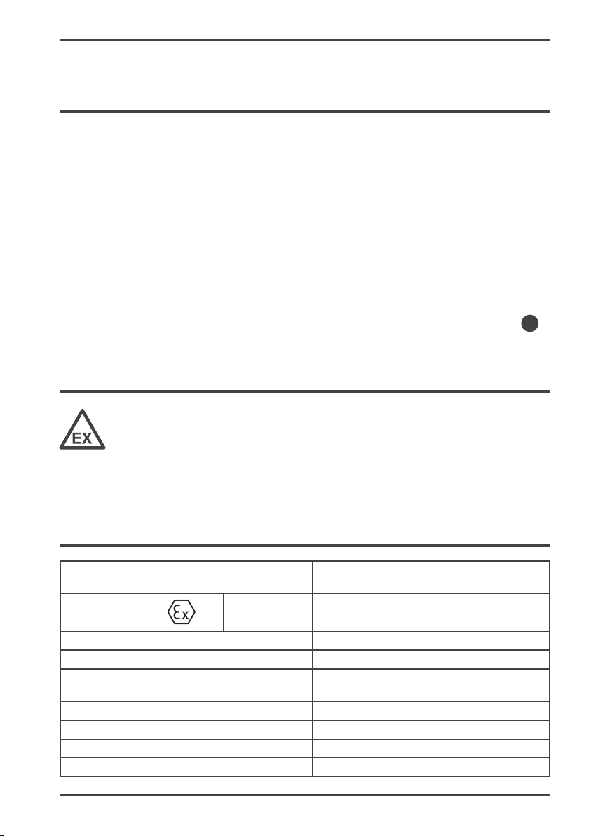
WARNUNG!
Wird der Aufhängewinkel der Kabelrolle nicht auf
eine leitende Unterlage, welche mit der Hausinstalla-
tion oder Masse verbunden ist, montiert, muss der
Aufhängewinkel auch an den Potentialleiter ange-
schlossen werden. Totalverlust der Funktion.
HINWEIS!
Das Anschliessen des Potentialleiters an die Kabelrolle
darf nur durch Fachpersonal ausgeführt werden.
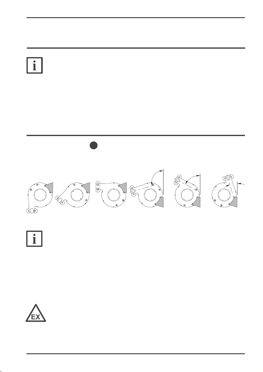
5.2. Montage der Zuleitung
1. Der Kabelquerschnitt der Zuleitung muss zwischen 3 mm² und 4 mm² betragen.
2. Gehäusedeckel entfernen.
3. Zuleitung Kabel-Ø 7 – 11 mm durch EX Kabelverschraubung (Bild A) führen.
4. Zuleitungskabelende 12mm abisolieren (Bild B)
5. Anschliessen der Zuleitung: Hebel «Z» öffnen – Zuleitungskabel einführen
(min. 11mm) und Hebel «Z» schliessen (Bild C)
6. Zugentlastung gemäss Skizzen (Bilder D) durchführen
7. EX-Kabelverschraubung festziehen bis Dichtsatz das Kabel satt umschliesst.
Bild A Bild B
Bilder D
2
6
7
6
7
Bild C
1
6
Kabel-Ø 7–9.5 mm Kabel-Ø 9.5–11 mm
Je nach Kabel-Ø wird die eine oder andere
Seite des Klemmteils verwendet.
Hebel «Z»
= 12 mm

KPX
EFCO BETRIEBSANLEITUNG 7
5.3. Messtechnische Prüfung
HINWEIS!
Nach Abschluss der Installation muss die Funktion des
Potenzialausgleichs durch eine Widerstandmessung
überprüft und dokumentiert werden.
6. Betrieb
6.1. Trommelarretierung
6.2. Freie Kabellänge
6.3. Lösen der Verbindung
Durch die Arretierung kann der Auf- und Abwickelvorgang des Kabels nach jeder
Trommelumdrehung gestoppt werden.
Die Arretierung lässt sich durch Drehen der Arretierschraube ein- und aus-
schalten.
• Mit Arretierung: Arretierschraube oberflächenbündig.
• Ohne Arretierung: Arretierschraube eingedreht (ca. 2 mm).
Die freie Kabellänge kann durch Verstellen des Kabelstoppers eingestellt
werden.
VORSICHT!
• Klemmenzangen-Verbindung nicht durch Ziehen am
Kabel trennen.
• Bei ausgezogener Potenzialausgleichsleitung muss
diese beim selbsttätigen Aufwickeln von Hand zu-
rückgeführt werden. Ein unkontrolliertes Zurück-
schnellen der Leitung kann zu Verletzungen führen.
3
a5

KPX
EFCO BETRIEBSANLEITUNG 8
7. Instandhaltung
7.1. Wartung und Reinigung
7.2. Inspektion
Kabel regelmässig feucht reinigen. Sicherstellen, dass kein Schmutz durch das
Kabel in das Gehäuseinnere gelangt.
Falls sich das Kabel aufgrund von Klebrigkeit des Mantels nicht mehr vollständig
aufwickeln lässt, kann dieses durch Behandlung des Kabelmantels mit Silikon oder
Specksteinpulver wieder funktionsfähig gemacht werden.
ACHTUNG!
Der Trommelraum der Kabelrolle darf nicht durch
Anwendung von Pressluft ausgeblasen werden. Es
besteht die Gefahr, dass dadurch Staub in die Trommel-
lager und Drehkupplung gelangt und damit die ein-
wandfreie Funktion nicht mehr sichergestellt ist.
HINWEIS!
Die Funktion des Potenzialausgleiches ist mindestens
1× jährlich durch eine Widerstandmessung zu überprü-
fen und zu dokumentieren.
• Anschlussklemmen regelmässig auf Beschädigung
und lose Schrauben prüfen.
• Klemmzange regelmässig auf Funktion und loses
Anschlusskabel prüfen.
4
WARNUNG!
Gehäuse der Kabelrolle darf nur mit feuchtem Tuch
gereinigt werden.
Gefahr der elektrostatischen Entladung

KPX
EFCO BETRIEBSANLEITUNG 9
7.3. Reparatur/Service
HINWEIS!
Reparaturen an der Kabelrolle dürfen nur vom Hersteller
durchgeführt werden. Die Kabelrolle selbst darf mit
Ausnahme des Gehäusedeckels nur durch den Her-
steller geöffnet werden. Durch die vorgespannte Spiral-
feder besteht Verletzungsgefahr!
• Serviceadresse: Siehe Hersteller
• Erdungsklemmzangen können unter Beizug von
Fachpersonal und unter Verwendung von Original-
ersatzteilen bei Bedarf durch den Kunden selbst
getauscht werden.
• Garantie: Es gelten die zum Zeitpunkt des Kaufes
gültigen Garantieleistungen des Herstellers.
8. Entsorgung/Umwelt
8.1. Umweltkonform nach
Die Kabelrolle besteht aus Kunststoff (PA), Stahl und wenig Buntmetall. Es gelten die
jeweiligen nationalen oder regionalen Abfallbeseitigungsvorschriften.
• Verordnung EG Nr. 1907/2006 (REACH) (Stand 01.01.2021)
• Richtlinie 2015/863/EU (RoHS) (Stand 01.01.2021)
9. EU-Konformitätserklärung (Nach RL 2014/34/EU Anhang X)
1. Produktmodell/Produkt
EX Rücklaufkabelrolle, Typ: KPX
2. Name und Anschrift des Herstellers
EFCO Befestigungstechnik AG
Grabenstrasse 1
8606 Nänikon, Schweiz
1

KPX
EFCO BETRIEBSANLEITUNG 10
3. Die alleinige Verantwortung für die Ausstellung der Konformitätserklärung trägt
der Hersteller.
4. Gegenstand der Erklärung
EX Rücklaufkabelrolle, Typ: KPX
5. Der oben beschriebene Gegenstand der Erklärung erfüllt die einschlägigen
Harmonisierungsrechtsvorschriften der Union:
RICHTLINIE 2014/34/EU DES EUROPÄISCHEN PARLAMENTS UND DES RATES
vom 26. Februar 2014
6. Angabe der einschlägigen harmonisierten Normen oder der anderen technischen
Spezifikationen, die der Konformitätserklärung zugrunde gelegt wurden:
EN ISO/IEC 60079-0: 2018
EN ISO/IEC 60079-7: 2016
EN ISO/IEC 60079-31: 2014
EN ISO/IEC 80079-34: 2017
7. Die notifizierte Stelle SEV 1258 hat in einer EU-Baumusterprüfung die Konformi-
tät festgestellt und folgende Bescheinigung ausgestellt:
SEV 20 ATEX 0367 X
8. Zusatzangaben
Keine
Unterzeichnet für und im Namen von
EFCO Befestigungstechnik AG
Grabenstrasse 1
8606 Nänikon, Schweiz
Nänikon, 30.1.2021
Thomas Doppelbauer, Leiter Qualität

KPX
EFCO BETRIEBSANLEITUNG 11
10. Abmessungen und Anbaumasse
112 mm
148 mm
62.5 mm 85.5 mm
71 mm
80 mm
110.5 mm
41.5 mm
89 mm
7 mm
a = 200 mm 270.5 mm
158.5 mm
Ø 212 mm
112 mm
A
A

KPX
EFCO OPERATING INSTRUCTION 12
1. General
The product
The EX rewind cable reel KPX with earthing clamp is used for temporary equipotential
bonding connections.
Intended use
The rewind cable reel KPX complies with ATEX device class II in categories 2G and 2D.
It is therefore intended for use in EX zones 1 and 21 or 2 and 22.
Content of delivery
Rewind cable reel in a robust plastic housing with equipotential bonding conductor and
a grounding clamp permanently connected to it. Optional: supply cable with ring eye
for screwing to earth.
2. Safety instructions
DANGER!
• The rewind cable reel is not allowed to be installed in
zones 0 and 20.
• Never connect under explosive atmosphere.
3. Technical data
Certification according to 2014/34/EU (ATEX)
Conformity to ISO/IEC 80079-34
SEV 20 ATEX 0367 X
SEV 20 ATEX 7374
Protection class Gas II 2G Ex eb IIC T6 Gb
Dust II 2D Ex tb IIIC T80°C Db
Ambient temperature (Tamb)-40°C ≤ Tamb ≤ +60°C
Case fibreglass-reinforced polyamide
Compensation conductor Stainless steel cable Ø2 mm encased in
PUR Ø7.75mm
IP protection class IP54
Connecting cable ≥3mm2
Dimensions LxWx H (300x 230 x155)mm without clamp
Weight 3.1kg incl. clamp
b

KPX
EFCO OPERATING INSTRUCTION 13
NOTICE!
• Do not install the cable reel in places where access
can be blocked and there is a risk of cable damage.
• Avoid installation locations where the cable could be
run over by vehicles.
5. Installation
Picture A
With the suspension bracket 6 different mounting positions are possible
(picture A).
4. Place of installation
0 ° 45 ° 90 ° 105 ° 60 ° 15 °
NOTICE!
The generally recognised state of the art according to
EN 60079-14 “Planning, selection and installation of
electrical installations” and these operating instruc-
tions are decisive for installation/operation.
DANGER!
Never connect under explosive atmosphere.
Danger of explosion
5.1. Starting up the supply line
2

KPX
EFCO OPERATING INSTRUCTION 14
WARNING!
If the suspension bracket of the cable reel is not
mounted on a conductive base which is connected to
the house installation or to earth, the suspension
bracket must also be connected to the potential con-
ductor. Total loss of function.
NOTICE!
The potential conductor may only be connected to the
cable reel by qualified personnel.
5.2. Mounting the supply line
1. The cable cross-section of the supply line must be between 3mm² and 4 mm²
2. Remove the housing cover .
3. Feed cable Ø 7 - 11 mm through EX cable gland (picture A).
4. Strip 12 mm of insulation from the end of the supply cable (picture B)
5. Connecting of the supply cable: open lever “Z” – feed in supply cable
(at least 11mm) and close lever “Z” (picture C)
6. Carry out strain relief according to the sketches (pictures D)
7. Tighten the EX cable gland until the seal kit tightly encloses the cable.
Picture A Picture B
Pictures D
2
6
7
6
7
Picture C
1
6
Cable Ø 7–9.5mm Cable Ø 9.5–11 mm
Depending on the cable Ø, one or the other
side of the clamping part is used.
Lever “Z”
= 12 mm

KPX
EFCO OPERATING INSTRUCTION 15
5.3. Measurement tests
NOTICE!
After completion of the installation, the function of the
equipotential bonding must be checked and document-
ed by measuring the resistance.
6. Operation
6.1. Drum lock
6.2. Free cable length (a)
6.3. Releasing the connection
Due to the locking device, the winding and unwinding process of the cable can be
stopped after each revolution of the drum.
The locking device can be switched on and off by turning the locking screw .
• With locking: Locking screw flush with the surface.
• Without locking: Locking screw screwed in (approx. 2 mm).
The free cable length can be set by adjusting the cable stopper .
ATTENTION!
• Do not disconnect the terminal clamp connection by
pulling the cable.
• If the equipotential bonding conductor is pulled out,
it must be returned by hand when it is automatically
wound up. Uncontrolled snapping back of the cable
causes injuries.
3
a5

KPX
EFCO OPERATING INSTRUCTION 16
7. Maintenance
7.1. Maintenance and cleaning
7.2. Inspection
Clean the cable regularly with a damp cloth. Ensure that no dirt gets through the
cable into the inside of the housing.
If the cable can no longer be wound up completely due to the stickiness of the
jacket, it can be made functional again by treating the cable jacket with silicone or
soapstone powder.
ATTENTION!
The drum space of the cable reel must not be blown
out by applying compressed air. There is a danger that
dust could gets into the drum bearings and rotary joint
and thus the proper function is no longer guaranteed.
NOTICE!
The function of the equipotential bonding must be
checked and documented at least once a year by
measuring the resistance.
• Check the connection terminals regularly for dam-
age and loose screws.
• Regularly check clamping pliers clamps regularly for
function and loose connection cable.
WARNING!
The housing of the cable reel may only be cleaned with
a damp cloth.
Hazard due to electrostatic discharges
4

KPX
EFCO OPERATING INSTRUCTION 17
7.3. Repair/Service
NOTICE!
Repairs to the cable reel may only be performed by the
manufacturer. With the exception of the housing cover
, the cable reel itself may only be opened by the
manufacturer. There is a risk of injury due to the pre-
tensioned spiral spring!
• Service address: See manufacturer
• Earthing clamps can be replaced by the customer
himself if necessary, with the assistance of qualified
personnel and using original spare parts.
• Warranty: The manufacturer’s warranties valid at the
time of purchase apply.
8. Disposal/environment
8.1. Environmentally compliant according to
The cable reel is made of plastic (PA), steel and a small amount of non-ferrous metal.
The respective national or regional waste disposal regulations apply.
• Regulation EC No. 1907/2006 (REACH) (Status 01/01/2021)
• Directive 2015/863/EU (RoHS) (Status 01/01/2021)
9. EU Conformity (According to Regulation 2014/34/EU Annex X)
1. Product model/product
EX Rewind cable reel, Type: KPX
2. Name and address of the manufacturer
EFCO Fixing Technology Ltd
Grabenstrasse 1
8606 Nänikon, Switzerland
1

KPX
EFCO OPERATING INSTRUCTION 18
3. The manufacturer bears sole responsibility for issuing the declaration of
conformity.
4. Subject of the declaration
EX Rewind cable reel, Type: KPX
5. The subject matter of the declaration described above complies with the relevant
Union harmonisation legislation:
DIRECTIVE 2014/34/EU OF THE EUROPEAN PARLIAMENT AND OF THE COUN-
CIL of 26 February 2014
6. Reference to the relevant harmonised standards or other technical specifications
on which the declaration of conformity is based:
EN ISO/IEC 60079-0: 2018
EN ISO/IEC 60079-7: 2016
EN ISO/IEC 60079-31: 2014
EN ISO/IEC 80079-34: 2017
7. The notified body SEV 1258 has assessed conformity in an EU Type Examination
and issued the following certificate:
SEV 20 ATEX 0367 X
8. Additional information
None
Signed for and on behalf of
EFCO Fixing Technology Ltd
Grabenstrasse 1
8606 Nänikon, Switzerland
Nänikon, 30/1/2021
Thomas Doppelbauer, Quality Manager

KPX
EFCO OPERATING INSTRUCTION 19
10. Product dimensions and installation dimensions
112 mm
148 mm
62.5 mm 85.5 mm
71 mm
80 mm
110.5 mm
41.5 mm
89 mm
7 mm
a = 200 mm 270.5 mm
158.5 mm
Ø 212 mm
112 mm
A
A

KPX
EFCO MODE D’EMPLOI 20
1. Généralités
Le produit
Le rouleau à câble à retour KPX avec pince de mise à terre est utilisé pour les liaisons
équipotentielles temporaires.
Fonctionnement prévu
L’enrouleur de câble de retour KPX est conforme à la classe II des appareils ATEX dans
les catégories 2G et 2D. Il est donc destiné à être utilisé dans les zones EX 1 et 21 ou
2 et 22.
Contenu de la livraison
Enrouleur de câble à retour en boîtier plastique robuste avec conducteur de liaison
équipotentielle et une pince de mise à terre qui y est reliée en permanence. Facultatif:
câble d'alimentation avec oeillet pour le vissage à la terre.
2. Consignes de sécurité
DANGER!
• L’enrouleur de câble à retour ne peut pas être instal-
lé dans les zones 0 et 20.
• Ne vous connectez jamais dans une atmosphère
ATEX.
3. Données techniques
Certification selon 2014/34/EU (ATEX)
Conformité à la norme ISO/IEC 80079-34
SEV 20 ATEX 0367 X
SEV 20 ATEX 7374
Classe de protection Gaz II 2G Ex eb IIC T6 Gb
Poussière II 2D Ex tb IIIC T80°C Db
Température ambiante (Tamb)-40°C ≤ Tamb ≤ +60°C
Boîtier polyamide renforcé de fibres de verre
Compensation potentielle Câble en acier inoxydable Ø2 mm gainé
extérieure PUR Ø7.75mm
Classe de protection IP IP54
Câble de raccordement ≥3 mm2
Dimensions Lx B xH (300x230x155)mm sans pince
Poids 3.1kg pince incl.
b
Table of contents
Languages: