manuals.online logo
Brands
  1. Home
  2. •
  3. Brands
  4. •
  5. Hubbell
  6. •
  7. Cables And Connectors
  8. •
  9. Hubbell 4-PLEX User manual

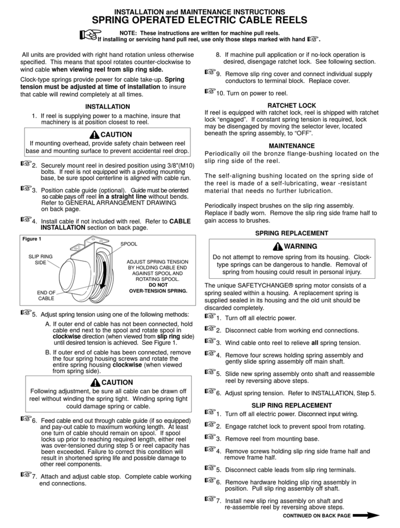
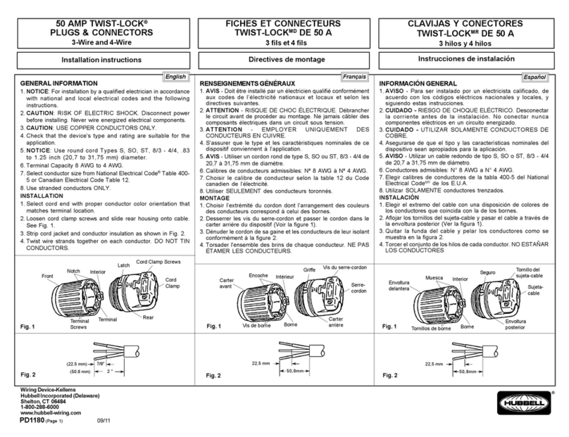
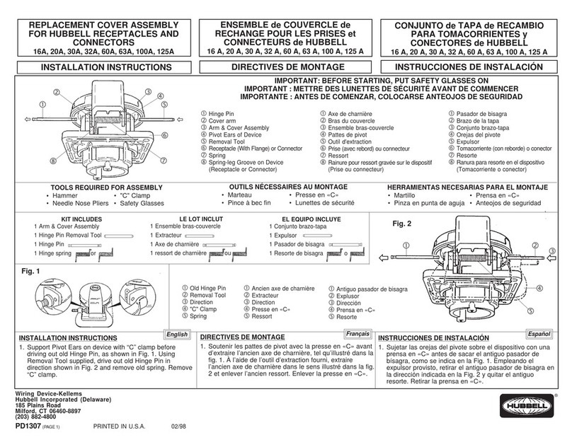
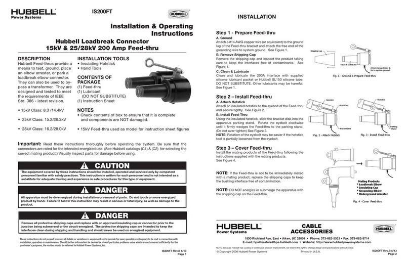
Hubbell 4-PLEX User manual

Hubbell
4-PLEXTM
Receptacles,Adapter
Plate,
and Portable
Box
WiringandAssembly
Instructions
READ
INSTRUCTIONS
COMPLETELY
PRIOR
TO INSTALLATION.
GENERAL
WIRING
INFORMATION:
Notice:
For
installationonly
bya
qualilied
electri-
cianin accordance
with
theNationalElectrical
Code9
Canadian
ElectricalCode,
and
local
code
requirements,
andthe following
instructions.
. Caution:
Riskofelectric
shock.Disconnect
power
before
installing.
Never
wireenergized
electrical
components.
Attention: Risquede chockelectrique.
D6branchef
lecircuit
avant
I'installation.
Ne
ia-
maisfaire
lesconnections
surcircuit
vivant.
Caution: Use
with
copperconductors
only.
Attention: Employer
uniquement
avefil de
culver.
Binding
headterminalscrews
accept
upto
#12
AWGsolidor stranded
conductors.
Do not
use
tinned'conductors.
Refer
to NECoTable
400-5orCECTable12
lor
ampacity
of
flexible
cords.
Useampacities
from
the60oCcolumn.
Portablebox
acceptscord
ranges16/3SJ
to 12l3SO.
. Reler
toNECOTable
310-16orCEC
Table2tor
ampacity
ot
insulatedconductors.
Use
conduc-
torswith
insulation
rated90oCor
higher
having
sufficient
ampacity
inaccordance
with
the
60oC
column.
NOTE
TO
INSTALLER:
lnstructions
should
be
left
withend user
tortuture
reference.
SURGE
SUPPRESSOR
RECEPTACLE
Refertogeneral
wiring
inlormation
(above
andbe-
low).
Connect
this
deviceonly
to
1
25VAC
max.
grounded
branch
circuit
withlisted
or certiliedover-current
orotectlon
rateclz$Fmax.(U.S.)
orattffibff
current
rating
(Canada).
Inadvertentconnection
to
a higher
voltage
willdamage
thedevice.Oiscon-
nectionof neutralconductor
while
circuit
isener-
gized
ona 1251250VACservice
could
produce
a
damaging
higher
voltage.
CAUTION:
RISKOF ELECTRIC
SHOCK.This
deviceis intended
for installationon a SINGLE
branch
circuit
(2-wire
plusground)
only" DO
NOTseparately
wirethe outletsof thisdevice
to
a multFwire
branchcircuit
(3-wire
plugground).
ATTENTION:
RISQUE
DE
CHOC
ELECTRIOUE.
Ce dispositil
est pour un installationsur un
courantSIMPLE
(2lils
et miseA laterre)seule-
ment. NE pasbrancher
s6parement
lesprises
du dispositif
sur un A circuit
multiple
branche'
ments
(3filset mise
a laterre).
This
device
maybewiredasa feed-thruunit
t0
protect
additional
outletson tf'e same
ci::rt
OPERATION
GREEN-Light
Emittin
Diode
(LED)
"ON"
indicates
that
power
is
onandsurge
protection
istunctioning.
Afaint
glow
of
iheredLED
is
noticeable
and
indi-
cates
LED
islunctioning
and
isin
astandby
condi-
tion.
When
the
green
LEDlight
goes
ouiand
the
red
LED
isBRIGHTLY
LlT,thereceptacle
is
no
longer
able
to provide
surgeprotection
becauseof damage
caused
by
large
transientsurgesbeyond
the
recep-
tacle's
rating.The
receptaclewillcontinue
tofunc-
tionwithout
surge
protection.
Replace
theentire
unit
immediately
to restoresurge
protection.
This
device
isnotalightning
arrestor
and
lightning
may
damage
theunit.
NOTICE
Do not hot wiresurge
suppressor
receptacle
-
doingsowilldamage
theunit
and
voidwarranty.
Turn
off
power
to
outlet
by
removing
fuseor
turning
oflcircuitbreaker.
lfan
existing
duplex
receptacle
is beingreplaced,shut oft power
to receptacle,
confirm
thatbothoutlets
are
not
powered
byusing
a testlamp. lf both
outlets
are
notpowered'
pro-
ceed
to
Step
1. lf
power
is
present
in
eithet
outlet,
the
existing
outlet
wassplit-wired.
Surge
suppres-
sorreceotacles
cannolbe used
to replace
a split-
wirereceotacle.
Adapter Plate
(2) Knockouts
for op'
tional4 screwmount-
ingto adapter
plate.
one receptacle),
consult
a qualified
electrician
for prop€r
wiringand installation.
Should
this
situation
exist,
do not anempt
installation
with-
outa oualified
electrician.
4. 4-PLEX
lsolated
Ground
lnstallations:
The4-
PLEXmaybe installed
as an "lsolated
ground"
device
it a separate
insulatedequip-
mentgrounding
wirehas beeninstalled
trom
theground
busat serviceentrance.
When
in-
stalled
thisway,the metallic
racewayandde-
vice box MUSTOe
grounded
to the normal
building
ground
system
andthe isolated
groundwireMUST
be connected
to the receP
tacte. Tne"lsolated
ground"
labelMUSTbe
placed
on the frontsurface
of the 4-PLEX
wherevisible
afterinstallation
for identifica-
tion requiredby the National
Electrical
Codeo
Section
410-56(c).
4-PLEX
RECEPTACLE
' SN€AK OFF.TAES
TERMINAL
SCREWS
EACK
V|EW
STRIPGAUGE
t Not accesible
or removeableon 4-PLEX
receptacleswithsurgesuppression.
@
AnchorHole
1. Mountadapter
dateto boxusing
(2)*32 x7l8
inchflat headscreu6. Position
flange
side
facingboxand pullcable
ftrougiltopening
in
adapter
Plate.
2. Stripinsulationon individualconductors
3/4
inchandwireeach
to proper
terminal;black
conductor
to brassscrew,
white
conductor
to
silverscrew,
green
or bareconductor
to
greengrounding
screw. Anchorconductor
in
anchor
holeprovided
andwrapin a counter-
clockwise
direction. Forlargersizeconduc-
tors,formloopandplace
under
headof termi-
nal screw. Tightenterminalscrews
1G12
pound-inches
(1.2
- 1,4N.m)ina clockwise
direction.
A grounding
ftilail is provid€d
to ground
recepta-
cle to a metallicboxwhereno grounding
con-
ductor
is available. (See
Step4 for isolated
Ground
installations.)
lf boxcontains
additional
conductors
to feed
otherrecegtacles
onthe samecircuit,
usere-
maining
terminal
screws
to connect
the con-
ductors. Followthe colorcodedesignations
above. Consulta qualified
electrician
if you
haveany
questions
concerning
theinstalla-
tion of this device:
Takeextra
caution
that
thereare no loose
strands.
3. 4-PLEXwithoutSurge
Suppression:
Two
breakofl trabs
are grovided
for splitcircuit
wir
ing. A and B circuit
identitication
is molded
intofaceof recegtacle.
lf you controla receptacleor portion
of the fe
ceptacle
lrom a wallswitch,or if the recepta-
cle hassplitcircuit
wiring
(twocircuitsfeeding
Hubbell
4-PLEXT'|
Box Mountings
Mounlreceptacle
toadapler
plate
usiirg
two
#B
x 5/16
pan-head
screws.
lnstallation
iscomplete.
For
optional4 screwmounting,
remove
twoknockouts
on
receptacle
and
c{rmpleleinstallation
usinglwoadditional
panhead
screws
provided.
CONCRETE
OCTAGON
RING
(Flush
Mounted)
Bemove
knockouts
indicated
and
mount
receptacle
using
#B x l
rnch
mounting
screws
provided
with
4.PLEX.
4''
OCTAGON
Remove
knockoutsindicated
and
mount
receptacle
using
#8 x 1
inchmounting
screws
provided
with
4-PLEX.
4"SQUARE
SURFACE
MOUNTED:
Mount
re-
ceptacle
usingtwo #8 x 1 inch
mounting
screws
provided
with
4-
PLEX.
FLtiSH
MOUNTED:
For
{tush
mounting,
mount
adapter
plate
to
box
using
two
#8
x 1inch
mount-
ing
screws
andmount4-PLEX
to
adapter
plate
using
two
#8x 5/.16
inch
pan-head
screws
provided
With4-PLEX.
2-GANG
Mount
adapter
plate
to 2 gang
boxusingtwo
6-32x7/8inch
flat
head screws provided with
adapter.
Mount 4-PLEX
to
adapter
plate
using
two
#8x5/16
inchpan-head
screws.
4" SQUARE
WITH
PLASTER
RING
(Flush
Mounted)
Mount
adapter
plate
to plaster
using
two 6-32x 718inchflat
head screws
provided
with
adapter
plate.
Mount
4-PLEX
to
adapter
plate
usingtwo
#8x5/1
6
inchpan-head
screws.
SINGLE
GANG
(Flush
Mounted)
Mount
adapter
plateto single
gang
box usingtwo 6-32
x 718
inch
flathead
screws
provided
with
adapter.Mount
4-PLEX
to
adapter
ptate
usingtwo
#8x5/16
inch
Dan-headscrews.
Hubbell
Portable
Non-Metallic
Boxes
PORTABI
F ROX
. Suitableforusewith4-Plex
Receptacles
only.
. For
15A,use12-14
AWG
wires.
. For
20A,use12
AWG
wires.
. Usestranded
copperwireonly.
. Do not usetinned
conductors.
Stripcordjackel4 inches
and individual
conductors3/4
inch.
Insert
cordthrough
openinginbox
andwireindivid-
ual
conductors
to proper
terminals;
black
conductor
to
brass
screw,whiteconductor
to silverscrew,
green
or
bare
conductorto
greengrounding
screw.Place
top
hall
of cord
gripovercordallo$,ing1/4inchof cord
iacket
to
extend
beyond
cord
grip.
Tightentwo
assembly
screws
untilcordissecure.Mountreceptacle
to boxusing
two
#8 x 5/16inchpan-head
screws.
Hubbell
Incorporated
Bridgeport,
CT06605
(203)
337-3100
D-55101-01 Printed
in U.S.A. Rev.z/92 @E'
Wiring DeviceDivision

Other Hubbell Cables And Connectors manuals

Hubbell KILLARK VSIH Series Owner's manual

Hubbell

Hubbell KILLARK VSIH Series Owner's manual

Hubbell 16A User manual

Hubbell

Hubbell 16A User manual

Hubbell GAI-TRONICS 400-005 User manual

Hubbell

Hubbell GAI-TRONICS 400-005 User manual

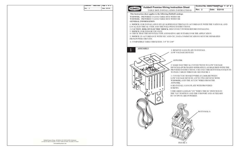
Hubbell WSB985BK User manual

Hubbell

Hubbell WSB985BK User manual

Hubbell INSULGRIP HBL3200RS2W User manual

Hubbell

Hubbell INSULGRIP HBL3200RS2W User manual

Hubbell IS628BT Manual

Hubbell

Hubbell IS628BT Manual

Hubbell SAFETY-SHROUD TWIST-LOCK User manual

Hubbell

Hubbell SAFETY-SHROUD TWIST-LOCK User manual

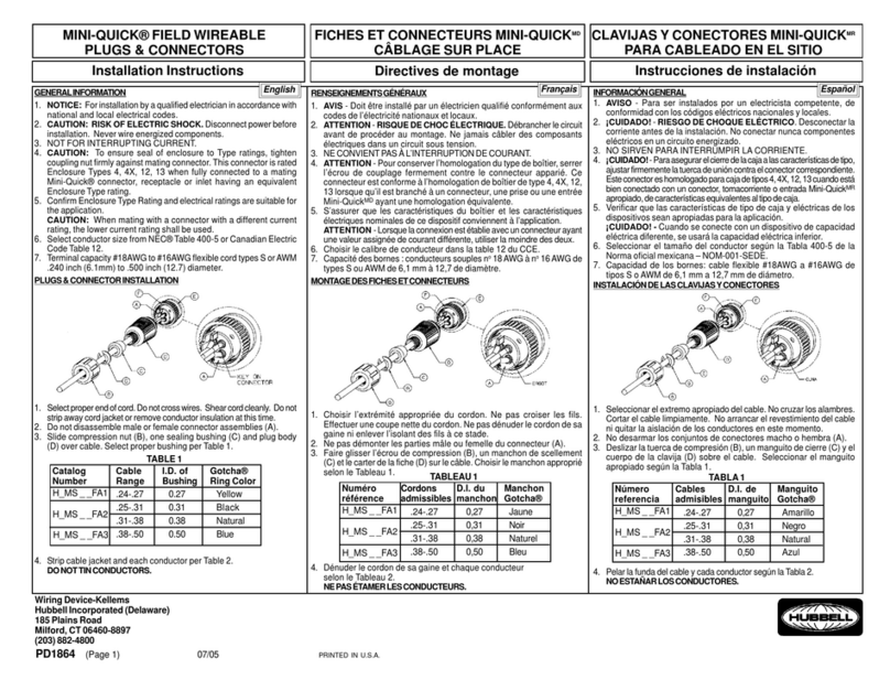
Hubbell MINI-QUICK H MS FA1 Series User manual

Hubbell

Hubbell MINI-QUICK H MS FA1 Series User manual

Hubbell GLEASON 602152 User manual

Hubbell

Hubbell GLEASON 602152 User manual

Hubbell Insulgrip User manual

Hubbell

Hubbell Insulgrip User manual

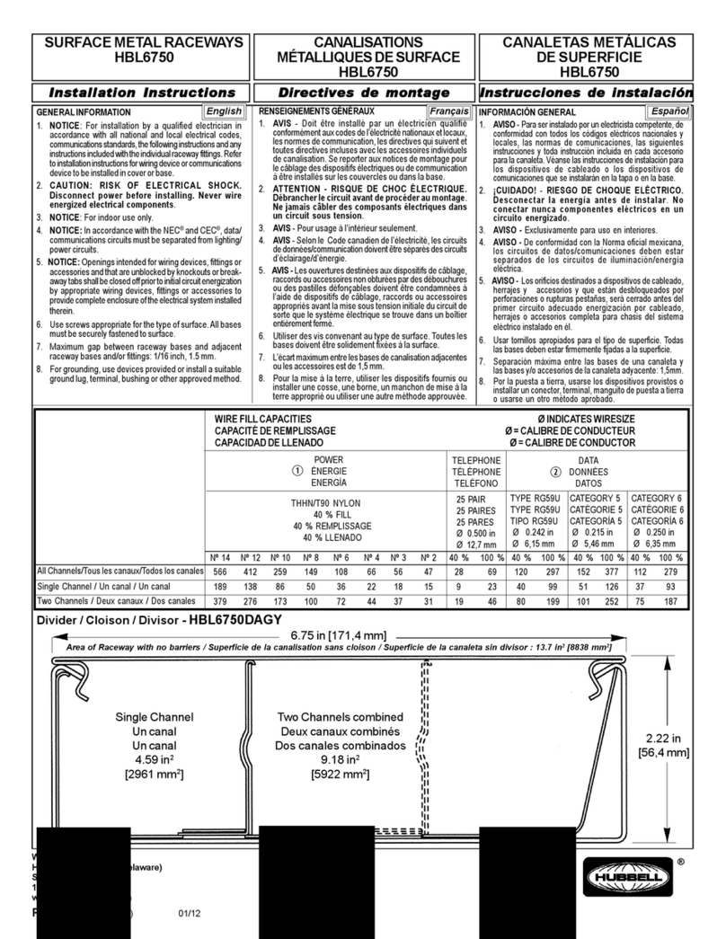
Hubbell HBL6750 User manual

Hubbell

Hubbell HBL6750 User manual

Hubbell 50 AMP TWIST-LOCK User manual

Hubbell

Hubbell 50 AMP TWIST-LOCK User manual

Hubbell 50 AMP TWIST-LOCK User manual

Hubbell

Hubbell 50 AMP TWIST-LOCK User manual

Hubbell 228FTV Manual

Hubbell

Hubbell 228FTV Manual

Hubbell HBLI35103Y User manual

Hubbell

Hubbell HBLI35103Y User manual

Hubbell KILLARK MC Series Instruction Manual

Hubbell

Hubbell KILLARK MC Series Instruction Manual

Hubbell HPS/RFL User manual

Hubbell

Hubbell HPS/RFL User manual

Hubbell Gleason Reel P28 Application guide

Hubbell

Hubbell Gleason Reel P28 Application guide

Hubbell HBLC40123 User manual

Hubbell

Hubbell HBLC40123 User manual

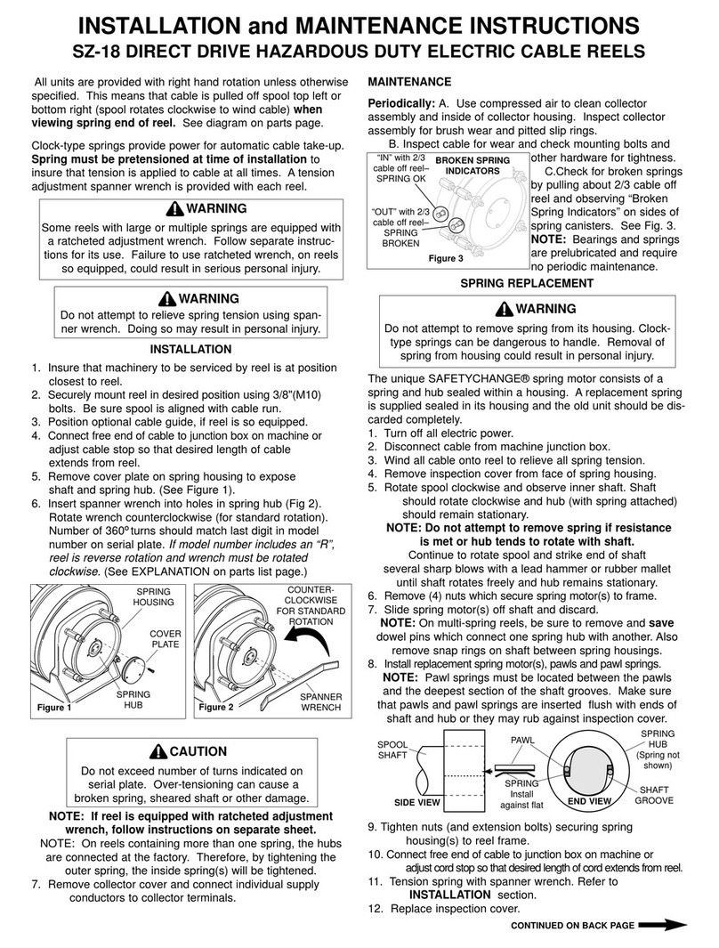
Hubbell Gleason Reel SZ-18 User manual

Hubbell

Hubbell Gleason Reel SZ-18 User manual

Popular Cables And Connectors manuals by other brands

Hyperkin M07433 quick start guide

Hyperkin

Hyperkin M07433 quick start guide

Nav TV BMW12N-H manual

Nav TV

Nav TV BMW12N-H manual

NI SCB-100 installation guide

NI

NI SCB-100 installation guide

Axxess AX-ADGM04 installation instructions

Axxess

Axxess AX-ADGM04 installation instructions

Staubli PV-KBT4-EVO 2-UR Assembly instructions

Staubli

Staubli PV-KBT4-EVO 2-UR Assembly instructions

Grandbeing Vision HD SP0104-U01 operating instructions

Grandbeing

Grandbeing Vision HD SP0104-U01 operating instructions

ADTRAN 1200487G80 manual

ADTRAN

ADTRAN 1200487G80 manual

Harman Kardon 150 manual

Harman Kardon

Harman Kardon 150 manual

IDEAL Networks LanTEK III MPTL Quick reference guide

IDEAL Networks

IDEAL Networks LanTEK III MPTL Quick reference guide

MAC Panel M02S006M Wiring Assembly Instructions

MAC Panel

MAC Panel M02S006M Wiring Assembly Instructions

Altera USB-Blaster user guide

Altera

Altera USB-Blaster user guide

NEUTRIK NAC3MX-W Operating & assembly instruction

NEUTRIK

NEUTRIK NAC3MX-W Operating & assembly instruction

Botex DM-2512 user manual

Botex

Botex DM-2512 user manual

Cablexpert GVS122 user manual

Cablexpert

Cablexpert GVS122 user manual

Philips SWV7432W Specifications

Philips

Philips SWV7432W Specifications

Philips SWA3162W Specifications

Philips

Philips SWA3162W Specifications

Gefen 1x4 HDMI Splitter user manual

Gefen

Gefen 1x4 HDMI Splitter user manual

PRO SIGNAL PSG03717 quick start guide

PRO SIGNAL

PRO SIGNAL PSG03717 quick start guide

manuals.online logo
manuals.online logoBrands
  • About & Mission
  • Contact us
  • Privacy Policy
  • Terms and Conditions

Copyright 2025 Manuals.Online. All Rights Reserved.