EFEN E3-LE-03MQ CT User manual

E3-LE-03MQ CT
Electric energy meter
1-phase / 3-phase
Bidirectional with network parameters analysis

2E3-LE-03MQ CT – User manual
CONTENTS
1. PURPOSE ............................................................................................................................................ 4
2. UNIT CHARACTERISTIC ....................................................................................................................
2.1. Measured values ......................................................................................................................
2.2. Current transformers (CT) ........................................................................................................
2.3. RS-485 communication port and Modbus RTU protocole .......................................................
2.4. Pulse output ............................................................................................................................
4
4
4
5
5
3. START-UP SCREENS ......................................................................................................................... 5
4. OPERATOR PANEL ............................................................................................................................
4.1. Voltage and current, harmonic .................................................................................................
4.2. Frequency, power factor and demand .....................................................................................
4.3. Power ......................................................................................................................................
4.4. Energy measurements ............................................................................................................
6
6
7
8
9
5. SETUP .................................................................................................................................................
5.1. Setup entry methods ...............................................................................................................
5.1.1. Navigation ............................................................................................................................
5.1.2. Number entry procedure ......................................................................................................
5.2. Setup parameters ...................................................................................................................
5.2.1. Entry into conguration menu ..............................................................................................
5.2.2. RS-485 communication .......................................................................................................
5.2.2.1. (Slave ID) Addres ..............................................................................................................
5.2.2.2. Baud rate .........................................................................................................................
5.2.2.3. Parity ...............................................................................................................................
5.2.2.4. Stop bits ..........................................................................................................................
5.2.3. Current transformers ...........................................................................................................
5.2.4. Measuring voltage .............................................................................................................
5.2.5. Pulse output ........................................................................................................................
5.2.5.1. Energy setup ....................................................................................................................
5.2.5.2. Pulse rate .........................................................................................................................
5.2.5.3. Pulse duration ..................................................................................................................
5.2.6. Demand Integration Time (DIT) ...........................................................................................
5.2.7. Backlit setup ........................................................................................................................
5.2.8. Measuring system ...............................................................................................................
5.2.9. CLR ......................................................................................................................................
5.2.10. Change password ..............................................................................................................
10
10
10
10
11
11
11
11
12
13
13
14
15
16
16
17
17
18
19
19
20
21

3
E3-LE-03MQ CT – User manual
6. TECHNICAL SPECIFICATION ............................................................................................................
6.1. Measured parameters ...............................................................................................................
6.1.1. Voltages and currents ............................................................................................................
6.1.2. Power factor, frequency and demand ....................................................................................
6.1.3. Energy measurements ...........................................................................................................
6.2. Terminal ....................................................................................................................................
6.3. Accuracy ...................................................................................................................................
6.4. Power supply and power meter ................................................................................................
6.5. Measurement inputs .................................................................................................................
6.6. Pulse outputs ............................................................................................................................
6.7. RS-485 output for Modbus RTU ................................................................................................
6.8. Reference conditions of inuence quantities .............................................................................
6.9. Environment ..............................................................................................................................
6.10. Structure ..................................................................................................................................
6.11. Compliance and sealing ...........................................................................................................
22
22
22
22
23
23
23
23
23
24
24
24
25
25
25
7. DIMENSIONS ....................................................................................................................................... 26
8. WIRING DIAGRAM ................................................................................................................................
8.1. Meter‘s power supply .................................................................................................................
8.2. Measuring systems ....................................................................................................................
26
26
27
9. MODBUS PROTOCOLE REGISTERS .................................................................................................
9.1. Input registers ............................................................................................................................
9.2. Setup registers ...........................................................................................................................
28
28
32

4E3-LE-03MQ CT – User manual
1.PURPOSE
E3-LE-03MQ CT is a static (electronic) calibrated electricity meter of single-phase or three-phase alternating current
in a direct system. It is used for reading and recording of consumed electric energy and mains parameters with remote
readout via a wired RS-485 network. The meter works with current transformers (CT) with 1 A or 5 A secondary current.
The conguration of the meter is done through the conguration menu accessible from the front panel and the commu-
nication port according to the software features of the Modbus RTU protocol.
2. UNIT CHARACTERISTICS
2.1. Measured value
The unit can measure and display:
• line voltage and THD% (total harmonic distortion) of all phases
• line frequency
• currents, current demands and current THD% of all phases
• power, maximum power demand and power factor
• active energy imported and exported
• reactive energy imported and exported
2.2. Current transformers (CT)
The meter works with current transformers (CT) with 1 A or 5 A secondary current. The appropriate value of rate and
the secondary current of the connected transformer should be set in the meter.
For example: using a 100/5 A current transformer, you should set the secondary current CT2 to 5 and the rate CTrate
to 0020. To get the CT rate to enter you need to divide a primary current value by the value of the secondary current
(100/5 = 20).
WARNING!
The settings for the current ratio ( CT2 and CT rate) and voltage ratio ( PT2 and PT rate) can only be made
once. It is a legal requirement of the MID Directive. Once set the rate cannot be changed.

5
E3-LE-03MQ CT – User manual
2.3. RS-485 communication port and Modbus RTU protocole
The meter is equipped RS-485 port with Modbus RTU protocole.
The RS-485 communication port allows you to connect meters into a network of remote reading.
2.4. Pulse output
The meter has two pulse outputs for mapping the counting of active and reactive energy.
Output 1 - Terminals 9/10 - programmable, can be set to work for active or reactive energy and parameters: impulsing
and pulse length.
Output 2 - Terminals 11/12 - for active energy, impulsing is 3200 pulse / kWh.
3. START-UP SCREENS
The rst screen lights up all display
segments and can be used as a display check.
Information about software version.
The interface performs a self-test and indicates
the result if the test passes.

6E3-LE-03MQ CT – User manual
4. OPERATOR PANEL
Buttons features:
Select the voltage and current display screens.
In set up mode, this is the „Left“ or „Back“ button.
Select the frequency and power factor display screens.
In set up mode, this is the „Up“ button.
Select the power display screens.
In set up mode, this is the „Down“ button.
Select the energy display screens.
In set up mode, this is the „Enter“ or „Right“ button.
4.1. Voltage and current, harmonic
Each successive pressing of the button selects a new range:
Phase to neutral voltages (3p4w).
Current on each phase.
Phase to neutral voltage THD% (3p4w).

7
E3-LE-03MQ CT – User manual
Current THD% for each phase.
4.2. Frequency, power factor and demand
Each successive pressing of the button selects a new range:
Frequency and power factor (total).
Power factor of each phase.
Maximum power demand.
Maximum current demand.

8E3-LE-03MQ CT – User manual
4.3. Power
Each successive pressing of the button select a new range:
Instantaneous active power in kW.
Instantaneous reactive power in kVAr.
Instantaneous volt-amps in kVA.
Total: kW, kvar, kVA.

9
E3-LE-03MQ CT – User manual
4.4. Energy measurements
Each successive pressing of the button selects a new range:
Imported active energy in kWh.
Exported active energy in kWh.
Imported reactive energy in kVArh.
Exported reactive energy in kVArh.
Total active energy in kWh.
Total reactive energy in kVArh.
The total value of the given energy is presented in two rows.

10 E3-LE-03MQ CT – User manual
The top row presents the higher values, the bottom row presents the lower values + fractional value.
For example:
Indications: 0027 - top row; 845.3 - bottom row presents the value of 27845.3 kWh.
5. SETUP
5.1. Setup entry methods
Some menu items, such as password and CT, require a four-digit number entry while others, such as supply system,
require selection from a number of menu options. After conrming the settings the meter conrms the adoption
of a new parameter by displaying for a moment the word „good“.
5.1.1. Navigation
1. Transition to the next position conguration menu.
2. Press to conrm your selection.
3. Edition of value (change of position number by +/- 1)
4. Having selected an option from the current layer, press to conrm your selection.
The SET indicator will appear.
5. Back to the higher menu level. The SET indicator will disappear and you will be able to use
the buttons, again to select further options.
6. exit the conguration menu to the measurements screen.
5.1.2. Number entry procedure
When setting up the unit, some screens require the entering of a nuber. In particular, on entry
to the setting up section, a password must be entered. Digits are set individually, from left to right.
The procedure is as follows:
1. The current digit to be set ashes and is set using the and buttons.
2. Press to conrm each digit setting. The SET indicator appears the last digit has been set.
3. After setting the last digit, press to exit the number setting routine. The SET indicator
will be removed.

11
E3-LE-03MQ CT – User manual
5.2. Setup parameters
5.2.1. Entry into conguration menu
To enter setup mode, pressing the button for 2 seconds, until the password screen appears.
Settung up is password-protected so you must enter the
correct password (default „1000“) before processing.
Press the button for 2 seconds.
If an incorrect password is entered, the display will show:
PASS Err
To exit setting-up mode, press repeatedly until the measurement screen is restored.
5.2.2. RS-485 communication
Setting the communication port parameters.
5.2.2.1. (Slave ID) Address
(Range 001 to 247)
From the set up menu, use and buttons
to select the address ID.
Press button to enter the selection routine.
The current setting will be ashing.

12 E3-LE-03MQ CT – User manual
Use and buttons to choose Modbus address
(001 to 247). Press button to conrm the selection.
Press button to return the main set up menu.
5.2.2.2. Baud rate
From the set up menu, use and
buttons to select the Baud rate option.
Press button to enter the selection routine.
The current setting will ash.
Use and buttons to choose baud rate:
2,4 / 4,8 / 9,6 / 19,2 / 38,4 [kbps].
Press button, to conrm the selection.
Press button to return the main set up menu.

13
E3-LE-03MQ CT – User manual
5.2.2.3. Parity
From the set up menu, use and
buttons to select the parity option.
Press to enter the selection routine.
The current setting will ash.
Use and buttons to choose
parity EVEN/ODD/NONE (default).
Press button to conrm selection.
Press button to return the main set up menu.
From the set up menu, use and
buttons to select the stop bit option.
Press to enter the selection routine.
The current setting will ash.
5.2.2.4. Stop bits
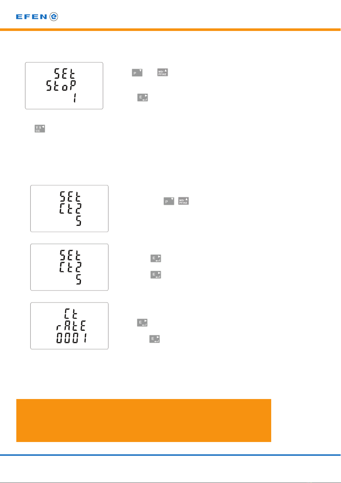
14 E3-LE-03MQ CT – User manual
Use and buttons to choose stop bits: 2 or 1.
NOTE: Default value is 1. Only in case parity
set up NONE, to change stop bits to 2.
Press to conrm the selection.
Press button to return the main set up menu.
5.2.3. Current transformers
Setting currents values of the connected transformers.
Use the buttons in the conguration
menu to select the value of the CT.
Secondary current
Hold down to enter the secondary current
setting mode: 5 A/1 A.
Hold down to conrm selection.
CT rate
Press to display the rate setting screen.
Range of 0001 to 9999.
Hold down to conrm selection.
For example: for 100/5 A current transformer set the CT2 to 5 and rate to 20.
To get the CT rate you need to divide a primary current value by the value
of the secondary current (100/5 = 20).
WARNING!
The CT rate can be set only once. It is a legal requirement of the MID Directive.
Once set the rate cannot be changed. The settings for the current ratio ( CT2 and CT rate)
and voltage ratio ( PT2 and PT rate) can only be made once.

15
E3-LE-03MQ CT – User manual
5.2.4. Measurement voltage
Setting the value of the input voltage directly or through transformers.
For half-indirect 1- or 3-phase measurement set the value PT2 to 400 and PTrate to 1.
Use the buttons in the conguration
menu to select the PT option.
Input voltage
Hold down to enter the PT2 input voltage
setting mode: from 100 to 500.
Hold down to conrm selection.
For half-indirect 1- or 3-phase measurement
set the value to 400.
PT rate.
Press to display the rate setting screen.
Range of 0001 to 9999.
Hold down to conrm selection.
For half-indirect 1- or 3-phase measurement
set the value to 1.

16 E3-LE-03MQ CT – User manual
5.2.5. Pulse output
Pulse output conguration no. 1.
5.2.5.1. Energy setup
The output can be set to provide a pulse for a denied amount of energy active (kWh) or reactive (kvarh).
From the setup menu, use and buttons
to select the pulse output option.
Press to enter the selection routine.
The unit symbol will ash.
Use and buttons to choose kWh or kVArh.
Press to conrm selection.
Press button to return the main set up menu.

17
E3-LE-03MQ CT – User manual
Press button to return the main set up menu.
5.2.5.2. Pulse rate
Setup value option kWh/kvarh per 1 pulse. Values: 0.01 / 0.1 / 110 / 100.
From the setup menu, use and buttons
to select the pulse rate option.
Press to enter the selection routine.
The current setting will ash.
Use and buttons to select
value: 0,01 /0,1 /1 /10 /100 per pulse.
Press to conrm the selection.
Press button to return the main set up menu.
5.2.5.3. Pulse duration
Option of setting pulse length for output. Values: 200, 100 or 60 ms.
From the setup menu, use and buttons
to select the pulse width option.
Press to enter the selection routine.
The current setting will ash.
Use and buttons to choose
value: 200, 100 or 60 ms.
Press to conrm the selection.

18 E3-LE-03MQ CT – User manual
5.2.6. DIT- Demand Integration Time
The options are: 5, 10, 15, 30, 60 minutes.
From the setup menu, use and buttons,
to select the DIT option.
The screen will show the currently selected
integration time.
Press to enter the selection routine.
The current time interval will ash.
Use and buttons to select
the time required.
Press to conrm the selection.
SET indicator will appear.
Press to exit the DIT selection routine and return to the menu.

19
E3-LE-03MQ CT – User manual
5.2.7. Backlit setup
The meter allows you to set the time of the backlight.
Time: 0 / 5 / 10 / 30 / 60 / 120 minutes.
Value 0 means that the backlight is always on.
Default lasting time is 60 minutes.
If it‘s setted as 5, the backlit will be o in 5 minutes from the
last time operation on the meter.
Use and buttons to select the time.
Press to conrm the selection.
5.2.8. Measuring system
Setup option for measuring system:
1P2W – 1-phase 2-wires system;
3P3W – 3-phases 3-wires system (without neutral wire);
3P4W – 3-phases 4-wires.
From the set up menu, use and
buttons to select the system option.
The screen will show the currently
selected power supply.
Press to enter the selection routine.
The current selection will ash.

20 E3-LE-03MQ CT – User manual
Use and buttons to select the required
system option: 1P2(W), 3P3(W), 3P4(W).
Press to conrm selection.
SET indicator will appear.
Press to exit the system selection routine and return to the menu.
SET will disappear and you will be returned to the main set up menu.
5.2.9. CLR
The meter provides a function to reset the maximum demand value of current and power.
From the setup menu, use and buttons
to select the reset option.
Press to enter the selection rout
The MD will ash.
Press to conrm selection.
Press to return to the main set up menu.
Table of contents
Popular Measuring Instrument manuals by other brands


TANEL Electronics
TANEL Electronics WIP-22D user manual

Keysight Technologies
Keysight Technologies N8262A P Series user guide

Avery Weigh-Tronix
Avery Weigh-Tronix M3060 User instructions

Energometrika
Energometrika EnergoM 400 user manual

Leviton
Leviton Series 2000 installation instructions

Tonghui Electronics
Tonghui Electronics TH1991 Operation manual


