TABLE
OF
CONTENTS
1
I
ntroduction
...
..........................................................................
6
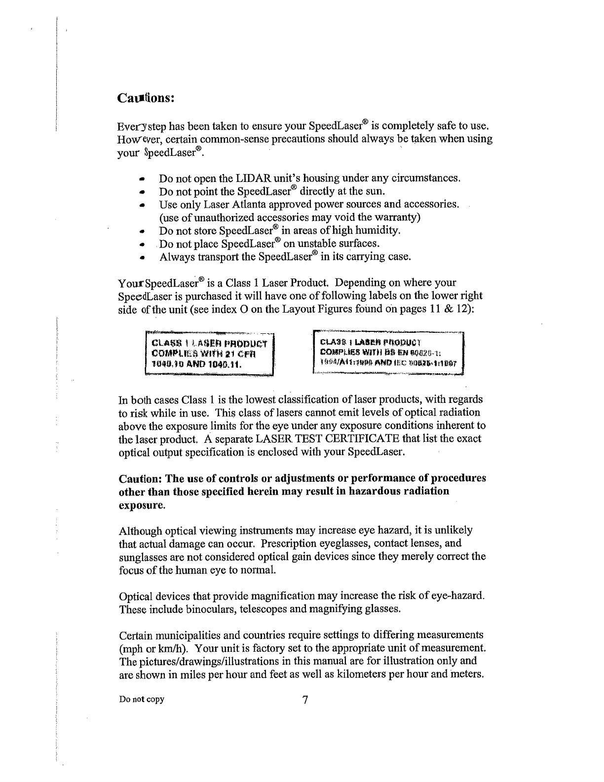
Cautions
................................................................................
7
Capabilities
..................................................
8
2
Getting
S
tarted
........
.
.............
.
..................
.
.......
.
................
10
Packing
List
...........
.
..............................................................................
10
SpeedLaser®
Controls
&
Layout
..................................................11
Battery
Handle
Power
..........................
.
.........................................
13
Connecting
a
Handle
........................................................................
14
To
Power
O
.........................................................................
.
...........
15
To
Power
OFF
..................................................
15
3
SPEED
MEASUREMENT
.........
.
.......................................
.
..........
.
6
Measuring
Speed
................................................................................
16
Approaching
and
Receding
Targets:
.........
.
..............................
17
Manufacturer's
Recommended
Daily
Test
..............................
18
4
U
ser
S
ettings
...................
..22
Intensity
and
Contrast
....................
22
LCD
Backlight:
.......................................................................
22
LCD
Contrast:
...................
22
HUD
Brightness:
......
22
The
ME U
System
.............................................................
23
Main
Menu
.............................................................................................
26
Test
Mode
..........................
27
Audio
........................
28
HUD
Mode
...............................................................
29
AIMI G
ME U
...................
30
Obstructed
Mode
................................................................................
32
5
Appendices
....................................
Do
not
copy
4