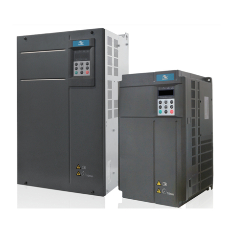
efes otomasyon IS300 Series User manual

IS300 Series User Manual Preface
1
Preface
IS300 series servo drive is a servo drive which is specially designed for drive permanent
magnet synchronous servo motor (PMSM). IS300 series servo drive has a wide capacity range
(the rated current is 5A to 300A).Itÿs able to provide not only servo pump control, but also the
general functional requirements. And it is a high-power servo drive which is value-for-money in
the present market.
This manual is a guide to the operations of IS300 series servo drive.
This manual provides the user with related precautions and instructions for the prototyping,
installation, parameter setup, and on-site trial run, and routine repair and maintenance of servo
drive. In order to use this series of drive correctly, please read this manual carefully prior to
operation and keep it properly for future using. The supporting equipment customers shall
distribute this manual together with the equipment to the final users.
Unpacking and inspection:
Please confirm carefully when unpacking the box:
If the model and drive rated values on the nameplate are the same as your order. The box
contains the equipment, certificate of conformity, user manual and warranty card.
If the product is damaged during the transportation. If there is any omission or damage, please
contact our company or the supplier immediately.
First time use:
The users who use this product for the first time shall read this manual carefully. For any doubt
on certain functions and performances, please contact the technical support personnel of our
company for help so as to use this product properly.
With commitment to the constant improvement of the servo drive, our company may change
the information provided without additional notice.
IS300 series servo drive complies with the following international standards, and some products
have passed the CE certification.
IEC/EN61800-5-1:2003 ĀSafety Regulations on Commissionable Electric Drive Systemāand
IEC/EN 61800-3:2004 Commissionable Electric Drive System: The third Part: Electromagnetic
Compatibility Standard and Specific Testing Method for the Product.
efesotomasyon.com

Content
Preface ĂĂĂĂĂĂĂĂĂĂĂĂĂĂĂĂĂĂĂĂĂĂĂĂĂĂĂĂĂĂĂĂ 1
Chapter 1 Product Information ĂĂĂĂĂĂĂĂĂĂĂĂĂĂĂĂĂĂĂĂĂĂ 4
1.1 IS300 Servo Drive Designation Rules ĂĂĂĂĂĂĂĂĂĂĂĂĂĂĂĂĂĂĂĂĂĂ 4
1.2 IS300 Servo Drive SeriesĂĂĂĂĂĂĂĂĂĂĂĂĂĂĂĂĂĂĂĂĂĂĂĂĂĂĂĂ 5
1.3 IS300 Servo Drive Brake Components Prototyping Table ĂĂĂĂĂĂĂĂĂĂĂĂĂĂ 6
1.4 IS300 Servo Drive External Electrical Parts Table ĂĂĂĂĂĂĂĂĂĂĂĂĂĂĂĂĂ 7
1.5 Physical Appearance and Installation Dimensions ĂĂĂĂĂĂĂĂĂĂĂĂĂĂĂĂĂ 8
Chapter 2 Wiring ĂĂĂĂĂĂĂĂĂĂĂĂĂĂĂĂĂĂĂĂĂĂĂĂĂĂĂĂĂĂĂĂĂ 2
2.1 Connection Mode ĂĂĂĂĂĂĂĂĂĂĂĂĂĂĂĂĂĂĂĂĂĂĂĂĂĂĂĂĂĂĂ12
2.2 Main Circuit Terminals and Connections ĂĂĂĂĂĂĂĂĂĂĂĂĂĂĂĂĂĂĂĂĂ13
2.3 Control Terminals and Connections ĂĂĂĂĂĂĂĂĂĂĂĂĂĂĂĂĂĂĂĂĂĂĂ13
2.4 IS300 Servo Drive Jumper Function Description ĂĂĂĂĂĂĂĂĂĂĂĂĂĂĂĂĂĂ15
2.5 Function Instructions of Servo Drive PG Card Terminals ĂĂĂĂĂĂĂĂĂĂĂĂĂĂ16
Chapter 3
Servo Pump Trial Run Steps and Prototyping of Servo Pump Optional Parts
Ă18
3.1 Servo Pump Trial run ProcessĂĂĂĂĂĂĂĂĂĂĂĂĂĂĂĂĂĂĂĂĂĂĂĂĂĂ18
3.2 Motor Trail Run ĂĂĂĂĂĂĂĂĂĂĂĂĂĂĂĂĂĂĂĂĂĂĂĂĂĂĂĂĂĂĂĂ19
3.3 Servo Pump Application Trail Run ĂĂĂĂĂĂĂĂĂĂĂĂĂĂĂĂĂĂĂĂĂĂĂĂ20
Chapter 4 Failure Diagnosis and Solution ĂĂĂĂĂĂĂĂĂĂĂĂĂĂĂĂĂ 24
4.1 Failure Diagnosis and Solution ĂĂĂĂĂĂĂĂĂĂĂĂĂĂĂĂĂĂĂĂĂĂĂĂĂ24
4.2 Common Fault and Resolution ĂĂĂĂĂĂĂĂĂĂĂĂĂĂĂĂĂĂĂĂĂĂĂĂĂ36
ISMG Servo Drive Using Instruction ĂĂĂĂĂĂĂĂĂĂĂĂĂĂĂĂĂĂĂĂĂĂĂĂĂ37
Chapter 5 ISMG Servo Drive Using Instruction ĂĂĂĂĂĂĂĂĂĂĂĂĂĂĂĂĂĂĂĂ38
5.1 ISMG Servo Drive Naming Rules ĂĂĂĂĂĂĂĂĂĂĂĂĂĂĂĂĂĂĂĂĂĂĂĂ38
5.2 ISMG Servo Motor Performance ParameterĂĂĂĂĂĂĂĂĂĂĂĂĂĂĂĂĂĂĂĂ39
5.3 ISMG Servo Motor Physical Dimension DiagramĂĂĂĂĂĂĂĂĂĂĂĂĂĂĂĂĂĂ41
5.4 Instructions of Supporting Board of ISMG Servo Motor Base Installation ĂĂĂĂĂĂĂ43
5.5 ISMG Servo Motor Wiring Instructions ĂĂĂĂĂĂĂĂĂĂĂĂĂĂĂĂĂĂĂĂĂĂ43
Appendix ĂĂĂĂĂĂĂĂĂĂĂĂĂĂĂĂĂĂĂĂĂĂĂĂĂĂĂĂĂĂĂ 45
Appendix 1 Common Parameters Table ĂĂĂĂĂĂĂĂĂĂĂĂĂĂĂĂĂĂĂĂĂĂĂ46
Appendix 2 Servo Motor Code Table ĂĂĂĂĂĂĂĂĂĂĂĂĂĂĂĂĂĂĂĂĂĂĂĂ52
efesotomasyon.com

Product Information
1
efesotomasyon.com

Product Information IS300 Series User Manual
4
Chapter 1 Product Information
1.1 IS300 Servo Drive Designation Rules
IS300 T 030 C L
IS300
Mark
SThree-phase 380V
Mark Voltage level
Rated output current 9A
Mark 005
13A
010
17A
015
25A
020
32A
030
37A
035
45A
040
60A
050
75A
070
91A
080
112A
100
150A
140
176A
170
210A
210
253A
250
304A
300
Rated output current
Mark
Rated output current
Corresponding relationship
2T Three-phase 220V
5T Three-phase 480
Universal servo oil pump drive
Series code
CMotor temperature overheating
protection PTC sensor with CAN
communication
Mark Interface board type
Null Forced air cooling in default
Mark Cooling method
LWater cooling
Note: With the rotary transformer
PG card as standard
efesotomasyon.com

IS300 Series User Manual Product Information
5
1.2 IS300 Servo Drive Series
Caution: Models in grey shading are custom models (water cooling drive)
Servo drive model Input voltage Power supply capacity
(kVA)
Input current
(A)
Rated output current
(A)
IS300T005-C
Three -phase
380V
Range˖
-15%20%
5.9 10.5 9.0
IS300T010-C 8.9 14.6 13.0
IS300T015-C 11.0 20.5 17.0
IS300T020-C 17.0 26.0 25.0
IS300T030-C 21.0 35.0 32.0
IS300T035-C 24.0 38.5 37.0
IS300T040-C 30.0 46.5 45.0
IS300T050-C 40.0 62.0 60.0
IS300T070-C 57.0 76.0 75.0
IS300T080-C 69.0 92.0 91.0
IS300T100-C 85.0 113.0 112.0
IS300T140-C 114.0 157.0 150.0
IS300T170-C 134.0 180.0 176.0
IS300T210-C 160.0 214.0 210.0
IS300T250-C 192.0 256.0 253.0
IS300T300-C 231.0 307.0 304.0
IS300T140-C-L 114.0 157.0 150.0
IS300T170-C-L 134.0 180.0 176.0
IS300T210-C-L 160.0 214.0 210.0
IS300T250-C-L 192.0 256.0 253.0
IS300T300-C-L 231.0 307.0 304.0
efesotomasyon.com

Product Information IS300 Series User Manual
6
1.3 IS300 Servo Drive Brake Components Prototyping Table
Caution: Models in grey shading are custom models (water cooling drive)
Servo drive model Recommended
rower of brake
resistor
Recommended
resistance value of
brake resistor Braking unit Remarks
IS300T005 300W ≥130¡
Built-in as
standard No special
specification
IS300T010 400W ≥90¡
IS300T015 500W ≥65¡
IS300T020 800W ≥43¡
IS300T030 1000W ≥32¡
IS300T035 1300W ≥25¡
IS300T040 1500W ≥22¡
IS300T050 2500W ≥16¡
IS300T070 3.7 kW ≥16¡Externally
connected MDBU-35-B
IS300T080 4.5 kW ≥16¡Externally
connected MDBU-35-B
IS300T100 5.5 kW ≥8¡Externally
connected MDBU-70-B
IS300T140 7.5 kW ≥8¡Externally
connected MDBU-70-B
IS300T170 4.5 kWh2≥8¡h2Externally
connected MDBU-70-Bh2
IS300T210 5.5 kWh2≥8¡h2Externally
connected MDBU-70-Bh2
IS300T250 6.5 kWh2≥8¡h2Externally
connected MDBU-70-Bh2
IS300T300 16kW ≥2.5¡Externally
connected MDBU-210-B
IS300T140-C-L 5000W ≥8¡Externally
connected MDBU-70-B
IS300T170-C-L 5000Wh2≥8¡h2Externally
connected MDBU-70-Bh2
IS300T210-C-L 5000Wh2≥8¡h2Externally
connected MDBU-70-Bh2
IS300T250-C-L 5000Wh2≥8¡h2Externally
connected MDBU-70-Bh2
IS300T300-C-L 5000Wh3≥8¡h3Externally
connected MDBU-70-Bh3
Note: h2 refers to two Braking units paralleled with their respective brake resistor; the meaning
of h3 is the same with h2.
efesotomasyon.com

IS300 Series User Manual Product Information
7
1.4 IS300 Servo Drive External Electrical Parts Table
Caution: Models in grey shading are custom models (water cooling drive)
Servo drive
model
Circuit
breaker
(MCCB)
A
Recom-
mended
contactor
A
Recom-
mended
input filter A
A
Recommend-
ed conducting
Wire of main
circuit at the
input side
mm2
Recom-
mended
conducting
wire of main
circuit at the
output side
mm2
Recom-
mended
conducting
wire of control
circuit
mm2
IS300T005 25 16 25 4 4 1.5
IS300T010 32 25 35 4 4 1.5
IS300T015 40 32 35 4 4 1.5
IS300T020 63 40 50 4 4 1.5
IS300T030 63 40 50 6 6 1.5
IS300T035 100 63 80 6 6 1.5
IS300T040 100 63 80 10 10 1.5
IS300T050 125 100 100 16 10 1.5
IS300T070 160 100 120 16 16 1.5
IS300T080 200 125 150 25 25 1.5
IS300T100 200 125 150 35 25 1.5
IS300T140 250 160 200 50 35 1.5
IS300T170 250 160 200 70 35 1.5
IS300T210 350 350 250 120 120 1.5
IS300T250 400 400 300 150 150 1.5
IS300T300 500 400 400 185 185 1.5
IS300T140-C-L 250 160 200 50 35 1.5
IS300T170-C-L 250 160 200 70 35 1.5
IS300T210-C-L 350 350 250 120 120 1.5
IS300T250-C-L 400 400 300 150 150 1.5
IS300T300-C-L 500 400 400 185 185 1.5
efesotomasyon.com

Product Information IS300 Series User Manual
8
1.5 Physical Appearance and Installation Dimensions
1.5.1 Physical appearance and installation dimensions of forced air cooling servo drive
Schematic Diagram for Physical Dimensions and Installation Dimensions
of IS300T005IS300T030
Schematic Diagram for Physical Dimensions and Installation Dimensions
of IS300T005IS300T030
efesotomasyon.com

IS300 Series User Manual Product Information
9
Model Mounting hole Physical dimensions Diameter of
mounting hole Weight (kg)
ABHH1 W D
IS300T005
148 236 248 / 160 183 ¶52.5
IS300T010
IS300T015
190 305 322 / 208 192 ¶66.5IS300T020
IS300T030
IS300T035
235 447 432 463 285 228 820IS300T040
IS300T050
IS300T070
260 580 549 600 385 265 ¶10 32IS300T080
IS300T100
IS300T140
343 678 660 700 473 307 ¶10 47
IS300T170
IS300T210
449 905 880 930 579 375 ¶10 90IS300T250
IS300T300
1.5.2 Physical appearance and Installation Dimensions of water cooling servo drive
Schematic Diagram for Physical Dimensions and Installation Dimensions of IS300T140-C-L
and IS300T170-C-L
efesotomasyon.com

Product Information IS300 Series User Manual
10
Schematic Diagram for Physical Dimensions and Installation Dimensions of IS300T210-C-L,
IS300T250-C-L and IS300T300-C-L
efesotomasyon.com

Wiring
2
efesotomasyon.com

Wring IS300 Series User Manual
12
Chapter 2 Wiring
2.1 Connection Mode
8
9
˳
3* FDUG
˄0 ' 3 * ˅
&15
( [WHUQDONH\ERDUG
LQ WH U ID F H
23
9
',
',
',
',
',
&20
$,
$,
*1'
3UHVVXUHFRP P DQGa9
)ORZ FRP P DQGa9
9
$,
*1'
3UHVVXUHVHQVRUVLJQDO
*1'
9
28738 7
3 7 & 3
37&1 7 KHUP LVWR U˄37&hhh˅
&$1+ &*1'
&$1/
% $
2LOSXP S
HQDEOHG
3,' VHOHFWLR Q WH U P LQDO
3,' 6HOHFWLR Q WH U P LQDO
) DXOWUHVHW
&$1&RP PXQLFDWLRQ( QDEOHGXVHZ KHQ
0XOWLSXP SSDUDOOHOIORZ
0 RWRURYHUKHDWLQJ
SURWHFWLRQWHUP LQDO
a9aP $
$FWXDOSUHVVXUH
RXWSXW a 9 aP $
(;&
(;&
6,1
6,1/2
&26
3 7& 35HVHUYHG
3 7& 15HVHUYHG
&26/2
37& 3
37& 1
37& 3
37& 1
8
9
:
/
/
/
(;&
(;&
6,1
6,1/2
&26
&26/2
5HGZKLWH
< HOORZ Z KLWH
\ H OOR Z
EOXH
UH G
EODFN
76 1 (
7KHFRORUHGOLQH
FRUUHVSRQGVWR7DP D
UR WDU\WUDQVIRUP HU
0 RGHO
76 1 )
3OHDVHFRQQHFW
WKHUPLVWRU
GHYLFHV7KHUP DO
JDOYDQLFGHYLFHV
FRQQHFWWRWKH
UHVLVWDQFHUX OHU
ORFDWLRQRIWKH
V\VWHP FRP SXWH U
7 RURLGDO& RUH DURXQG RQH FLUFOH
6KLHOGHG
QHWZRUN
6KLHOGHG1HWZRUN
& RQQHFWRUPHWDOVKHOO
* HQHUDOO\WKHPRWRU
WKHUPLVWRUFRQQHFWVWR
3 7& 3DQG37&1
6 \VWHP & RP SXWHU
*1'
) HUULWH% HDG ,QWKHVDP H
GLUHFWLRQDURXQGWZ RFLUFOHV
) HUULWH% HDG ,QWKHVDP H
GLUHFWLRQDURXQGWZ RFLUFOHV
) HUULWH% HDG ,QWKHVDP H
GLUHFWLRQDURXQGWZ RFLUFOHV
a9aP $
$FWXDOIORZ RXWSXWa9 aP $
*1'
) HUULWH% HDG ,QWKHVDP HGLUHFWLRQ
DURXQGWZ RFLUFOHV
$2
$2
*1'
7$
7%
7&
7$
7&
7$
7&
˄5 (/$<)DXOWRXWSXW˅
˄5(/$<˖6ZDVKSODWHVZ LWF K LQ J R I
GRXEOHGLVSODFHP HQWSOXQJHUSXP S˅
˄5(/$<˖
Pressure control status
output
˅
6(1625
5
6
7
5
6
7
)LOWH U
& RQWDFWRU0 &
&LUF X LW%UHDNHU
0 &&%
7 RURLGDO& RUH
D URXQG RQH FLUFOH
/
/
/
3
(
/
/
/
3
(
6KLHOGHG
QHWZRUN
6KLHOGHGQHWZRUN
% UDNH& LUFXLW
& RQQHFWLRQ
˄˅ ˄ ˅ 3 %
% UDNH5 HVLVWRU
,6 7,6 7
˄˅ ˄˅
%UDNH
5 HVLVWRU
0'%8
,6 7,6 7
˄˅ ˄˅
%UDNH5 HVLVWRU
0'%8
3
([WHUQDO
5 HDFWRU
,6 7,6 7
6 FKHP DWLF' LDJUDP
IRU & RQQHFWLRQRI
0 DLQ& LUFXLWDQG
& RQWURO7HUP LQDOV
% UHDN& LUFXLW& RQQHFWLRQV
6KLHOGHGWZLVWHG SDLU
FDEOLQJ
6KLHOGHGWZLVWHG
SDLUFDEOLQJ
9
$,
*1' *1'
9
28738 7 6(1625
6KLHOGHG
QHWZRUN
3 RZ HU6 XSSO\
*1' 9
$ GRSWWKHFRQQHFWLRQ P RGHRIWKH H[WHUQDOSRZ HUVXSSO\
SUHVVXUHVHQVRUUHFRP P HQHG
) HUULWH% HDG ,QWKHVDP HGLUHFWLRQ
DURXQGWZ RFLUFOHV
) HUULWH% HDG ,QWKHVDP H
GLUHFWLRQDURXQGWZ RFLUFOHV
) HUULWH% HDG ,QWKHVDP HGLUHFWLRQ
DURXQGWZ RFLUFOHV
) HUULWH% HDG ,QWKHVDP H
GLUHFWLRQDURXQGWZ RFLUFOHV
) H UULWH%HDG,QWKHVDPH
GLUHFWLRQDURXQGWKHWZRFLUF OHV
6KLHOGHG
QHWZ RUN
+ DQJLQWKHDLU
efesotomasyon.com

IS300 Series User Manual Wring
13
2.2 Main Circuit Terminals and Connections
Terminals Name Description
RǃSǃT
RǃS and T
Input terminal of three-
phase power supply AC single-phase 220V power connection point
(+)ǃ(-)(+)
and (-)
Negative and positive
terminals of DC bus
Shared DC bus input point (connection point of external
braking unit of above IS300T070˄included˅
(+)ǃPB(+)
and PB
Connecting terminal of
brake resistor
Connection point of brake resistor of below
IS300T050(included)
Pǃ(+)P and
(+)
Connection terminal of
external reactor
Connection point of external reactor above
IS300T140(included)
UǃVǃW U,
V and W
Output terminal of
servo drive Connect the three-phase motor
Earth terminal Earth terminal
2.3 Control Terminals and Connections
Type Terminal Terminal name Function description
power supply
+10V-GND 10V power supply
Provide 10Vf10% power supply for external-
units, and the maximum output current is 10mA.
It is generally used as the operating power
supply for the external potentiometer.
The potentiometer resistance range is 1 k¡to
5k¡.
+13V-GND Pressure sensor power
supply
Provide 13Vf10% power supply for external
units.
The maximum output current is 10mA.
It is generally used as the operating power
supply for pressure sensor.
+24V-COM ˇ24V power supply
Provide +24V power supply for external units. It
is generally used as the operating power supply
for digital input/output terminals.
24Vf10%, no-load virtual voltage can not
exceed 30V.
The maximum output current is 200mA. It is
internally insulated with GND.
OP External power input
terminal
COM and 24V is internally insulated .Connect to
24V by default upon delivery.
When external signal is used to drive DI1toDI5,
OP needs to connect to the external power
supply and disconnect from the +24V power
terminal.(It is determined by the J7 jumper on
the control board.)
efesotomasyon.com

Wring IS300 Series User Manual
14
Type Terminal Terminal name Function description
Analog Input
AI1-GND
Analog input terminal 1
˄default pressure
setting˅
1ǃInput Voltage range˖f10V
The resolution is 12 bit.
The correction precision is 0.5%.
2ǃInput resistance˖100k¡DŽ
AI2-GND Analog input terminal 2
˄default flow setting˅
1ǃThe resolution is 12 bit, the correction
precision is 0.5 %.
2ǃInput resistance˖100k¡DŽ
AI3-GND
Analog input terminal 3
˄default pressure sensor
signal input˅
1. Input range: f10V/0 to 20mA, which is
determined by J5 jumper on the control board.
There is 12-bit resolution; the correction
precision is 0.5 %.
2. Input impedance: It is 100k¡at the time of
voltage input and 500¡at the time of current
input.
Digital Input
DI1DI5-
COM
Digital input 1
1ǃInsulate drain-to-source input programmable
terminals, input frequency is less than 100 Hz;
2ǃInput resistance˖3.3k¡
3ǃVoltage range for level input˖9Vto 30V.
PTCP-PTCN Motor overheating
protection input
Motor overheating protection PTC sensor,
support PTC130 ǃPTC150 etc.
Communication
Terminal
CANH/
CANL/
CGND
CAN Communication
terminal
The highest communication speed is 1Mbps.
Whether to connect terminal resistance is
determined by the J8 jumper on the control
board.
485B/
485A
485 Communication
terminal
Retain the terminal without the function by
default, the highest communication speed is
230Kbps with isolation. Whether to connect
terminal resistance is determined by the J9
jumper on the control board.
Analog
Output
AO1-GND Analog output 1
The voltage or current output is determined by
the J4 jumper on the control board.
Output range: 0V to 10V and 0mA to 20mA.
There is 12-bit resolution.
The correction precision is 1 %.
The maximum load resistance value is not less
than 500¡.
AO2-GND Analog output 2
The voltage or current output is determined by
the J6 jumper on the control board.
Output range: 0V to 10V and 0mA to 20mA.
There is 12-bit resolution.
The correction precision is 1 %.
The maximum load resistance value is not less
than 500¡.
Relay
output
T/A1-T/B1 Normally closed terminal Contact driving capacity:
AC250Vˈ3AˈCOS¶=0.4DŽ
DC 30Vˈ1ADŽ
T/A1T/A
3-T/C1T/C 3
Normally open terminal
Auxiliary
interface
CNR1 External keyboard
interface
External keyboard and parameter copy unit
interface
efesotomasyon.com

IS300 Series User Manual Wring
15
2.4 IS300 Servo Drive Jumper Function Description
Jumper
number
Jumper
position Function description Jumper
position Function description
J2
GND terminal connect-to-
ground capacitance(Adopt
when the drive connect-to-
ground)
GND terminal connect-to-ground
capacitance(Adopt when the
drive connect-to-ground)
J3
GND terminal connect-to-
ground capacitance(Adopt
when the drive connect-to-
ground)
GND terminal connect-to-ground
capacitance(Adopt when the
drive connect-to-ground)
J4 AO1 output in the form of
voltage˄DC0 to 10V˅
AO1 output in the form of voltage
˄0 to 20mA˅
J5 AI3 input in the form of voltage
˄DC-10 to +10V˅
AI3 input in the form of voltage˄0
to 20mA˅
J6 AO2 output in the form of
voltage˄DC0 to 10V˅AO2 output in the form of current
J7 Internal power supply drives
the input terminal DI1 to DI5
External power supply drives the
input terminal DI1 ~ DI5
J8
CAN communication connect to
terminal resistors, the terminal
equipment adopt when multi-
machine communications,.
CAN communication does not
connect to terminal resistors, the
middle equipment adopt when
multi-machine communications.
J9
485 communication connect
to the terminal resistors, the
terminal equipment adopt
when multi-machine communic
ations,
485 communication does not
connect to the terminal resistors,
the middle equipment adopt when
multi-machine communications,
Note: Jumper position indicates the position of connection terminals observation
efesotomasyon.com

Wring IS300 Series User Manual
16
2.5 Function Instructions of Servo Drive PG Card Terminals
Item Name Description
1 EXC Excitation Signal
2 /EXC
3SIN
SIN Feedback Signal
4 SINLO
5COS
COS Feedback Signal
9COSLO
6
-- --7
8
Note˖Description of Specialized signal Lines for IS300 Servo Drive (for reference)
Signal Definition EXC- EXC+ SIN+ SIN- COS+ COS- PTC+ PTC-
Color of Encoder Cable
Line Specialized for IS300
Servo Drive
Red Blue Pink Grey Yellow Green White Brown
Corresponding
ĀMD38PG4āPG Card Pin
12345967
efesotomasyon.com

Servo Pump Trial Run Steps and Prototyping
of Servo Pump Optional Parts
3
efesotomasyon.com

Servo Pump Trial Run Steps and Prototyping of Servo Pump Optional Parts
IS300 Series User Manual
18
Chapter 3 Servo Pump Trial Run Steps and
Prototyping of Servo Pump Optional Parts
3.1 Servo Pump Trial run Process
6HUYRGULYHU
FRPPLVVLRQLQJ
6 H WWK H UH OHYDQWSDUDP HWHUVFRUUHFWO\
0 RWRUSDUDP HWHUWXQLQJ
0 RWRUFRP P LVVLRQLQJDGMXVWSDUDP HWHUV
RIWKHVSHHGDQGFXUUHQWORRS
2LOS UH V V X UH F R Q WUR OP RGHVHWXS
0 RWRUSDUDP HWHU˄)˅
& RQWUROSDUDP HWHU
˄$ǃ)ˉ˅
0RWRU
FRPPLV
VLRQLQJ
$ ,] H UR G ULIWDXWRP DWLFFRUUHFWLRQ
)XQFWLRQSDUDP HWHUVHWXS
,Q MHFWLRQP ROGLQJP DFKLQHFRP P LVVLRQLQJ
DGMXVWSUHVVXUHORRSSDUDP HWHU
6HUYR
SXP S
DSSOLFDWL
RQ
)LQLVK
0 RWRUSDUDP HWHUWXQLQJ
˄)˅
0 RWRUUHVSRQVHSDUDP HWHU
˄)˅
2LOS UH V V X UH F R Q WUR OP RGH
˄$ ˅
$,]HURGULIWDXWRFRUUHFWLRQ
˄$ ˅
)ORZ DQGRLOS UH V V X UH
FRP P DQG˄$ǃǃ˅
3 UHVVXUHUHOLHI˄$˅
0LQLPXPIORZ ˄$˅
0LQLP XP SUHVVXUH˄$˅
2LOS UH V V X UH 3 ,' ˄ $ ˅
1RWH˖˄˅'HWDLOHGLQVWUXFWLRQVSOH D V H UH IH UWR WK H IR OORZ LQJFRUUHVSRQGLQJFRQWHQWV
˄˅'RQRWFRQGXFWWKHFRP P LVVLRQLQJVWHSVZ LWK LWFDQDOV R V WD UWWK H LQMHFWLRQP ROGLQJP DFKLQHDFWLRQ
ǃ
ǃ
efesotomasyon.com

IS300 Series User Manual
Servo Pump Trial Run Steps and Prototyping of Servo Pump Optional Parts
19
3.2 Motor Trail Run
3.2.1 Set motor parameters of group F1˄F1-00 to F1-05ˈF1-15˅
3.2.2 Set pole-pairs number of the rotary encoder
3.2.3 Set the drive to non-oil pressure control mode˖A3-00 ˙Ā0ā
3.2.4 Set the drive to operation panel control mode, at this time the light of LOCAL/REMOT is
off.
3.2.5 Motor parameter tuning( automatic identification) ˄F1-16˅
F1-16˙Ā0ā: No operation. It doesnÿt conduct the motor parameters tuning.
F1-16˙Ā1ā: Static tuning. Adopt when the motor back EMF is known. Run the motor at the
low speed without opening the overflow valve during tuning.
F1-16˙Ā2ā˖Dynamic tuning. Adopt it when the motor back EMF is unknown. Run the motor
at the high speed with opening the overflow valve during tuning. Carrier tuning will affect the
precision of the motor parameters tuned, affecting the system control effectiveness.
a)If correctly set F1 group motor parameters (F1-00 to F1-05ǃF1-15)and the rotary encoder
number of pole-pairs(A1-04), just only conduct F1-16˙Ā1ā(static tuning).
b) If it is only able to correctly set F1 group motor parameters (F1-00 to F1-05), rotary encoder
number of pole-pairs (A1-04) was unable to determine the F1-15 (back EMF), you must
conduct F1-16 =āĀ1ā(dynamic tuning).
The numerical value of parameter F1-16 will restore to zero automatically after tuning.
If the drive alarm Err43 in the tuning process, it indicates that the encoder feedback signal is
wrong, please check the encoder signal wiring and installation precision.
3.2.6 When at trial run, set running frequency (F0-08), run by using the operation panel, while
detecting whether the output current is normal, whether the motor is running quietly, and the
way of using the operator .Please refer to the operation and display of Chapter 4.
Look into whether the running direction of the drive is correct, if it is correct, please swap motor
wiring arbitrary two-phase UVW and recheck motor parameters tuning. Then trial run.
If there is abnormal running, please check the motor parameters (F1 groups) and rotary
encoder number of pole-pairs (A1-04) setup, and then restart the motor parameters tuning,
then trial run.
Motor has oscillation when running or sends a low voice, please weaken the speed
loop(F2-00ǃF2-01ǃF2-03ǃF2-04) and current loop(F2-13ǃF2-14ǃF2-15ǃF2-16)
appropriately˄reduce the value of F2-00ǃF2-03ǃF2-13ǃF2-14ǃF2-15ǃF2-16ˈincrease
the value of F2-01ǃF2-04˅.
Motor running speed is not steady, please enhance speed loop(F2-00ǃF2-01ǃF2-03ǃF2-04)
and current loop(F2-13ǃF2-14ǃF2-15ǃF2-16) appropriately.(Increase the value of F2-00ǃ
F2-03ǃF2-13ǃF2-14ǃF2-15ǃF2-16.Reduce the value of F2-01ǃF2-04)
NOTE: The slow response of the speed and current loop will affect the pressure stability
directly, if the condition allows, please set the stronger speed loop and current loop response.
efesotomasyon.com

Servo Pump Trial Run Steps and Prototyping of Servo Pump Optional Parts
IS300 Series User Manual
20
3.3 Servo Pump Application Trail Run
3.3.1 AI zero drift auto-correction (A3-20)˖
Note: Make sure that the drive runs at zero speed before Al zero drift auto-correction
F00-08= Ā0ā, start ĀRUNāsignal. Please make sure F00-02= Ā0ā
Set AI zero drift auto correction parameter A3-20 to 1, the drive will conduct an AI zero drift auto
correct operation:
Write the detection value zero drift of three analog channel into the parameters, they are F4-18
(AI1 is the minimum input), F4-23 (AI2 is the minimum input), F4-28 (AI3 is the minimum input).
The detection value of zero drift can be found at U1-07, U1-08, and U1-09.
3.3.2 Oil pressure control mode selection˄A3-00˅:
A3-00˙Ā0ā˖Non- Oil pressure control modea)
A3-00˙Ā1ā˖Drive oil pressure control mode 1.CAN provides oil pressure commandb)
and flow command, AI3 analog Channel provides oil pressure feedback command, the
drive conducts oil pressure control.
A3-00˙Ā2ā˖Drive oil pressure control mode2. AI1 provide oil pressure command,c)
AI2 analog channel provide flow command, AI3 analog Channel provides oil pressure
feedback command, and the drive conducts oil pressure control.
A3-00˙Ā3ā˖ Oil pressure control mode (special use), the control parameters ofd)
group A3 servo pump control group are inactive.
A3-00˙Ā4ā˖Reserved.e)
3.3.3 Auto-setup of the parameters in the oil pressure control mode
When the non-oil pressure mode switches to the oil pressure mode (A3-00ĮĀ0ā), the
relevant parameters will be automatically set. See the following table for details.
Function
Code Function Code Description Setup
F0-01 Control mode 1(Vector control mode)
F0-02 Command source 1(Terminal command source)
F0-03 Frequency source
If A3-00˙Ā2ā, F0-03˙Ā3 ā(A I2 is frequency
source).If A3-00˙Ā1āor Ā3ā, F0-03˙
Ā9ā(Communication setup is frequency source)
F0-07 Frequency source
selection 0 (Non-auxiliary frequency source)
F0-17 Speed-up time 0.0s
F0-18 Speed-down time 0.0s
F1-00 Motor type
selection 2(Synchronous motor)
F4-00 DI1 terminal
function selection 11˄Running enabled˅
efesotomasyon.com
This manual suits for next models
37
Table of contents
Popular Servo Drive manuals by other brands
Panasonic
Panasonic MINAS A6 Series operating instructions
Lenze
Lenze PROFINET 9400 Communications manual
SYNAPTICON
SYNAPTICON SOMANET Node 400 Documentation
Delta Electronics
Delta Electronics ASDA-B2 series user manual
THORLABS
THORLABS DDSM50 Series user guide
Rockwell Automation
Rockwell Automation Allen-Brandley Kinetix 3 Original instructions
Metronix
Metronix APM-SA Series quick start guide
Honeywell
Honeywell MT4000 Series instruction sheet
YASKAWA
YASKAWA SERVOPACK Sigma 7S Series Supplementary manual
Nidec
Nidec Unidrive M700 Parameter guide
Mitsubishi Electric
Mitsubishi Electric Melservo-Jet HG-SNS Series user manual
Inovance
Inovance IS580 Series user guide
