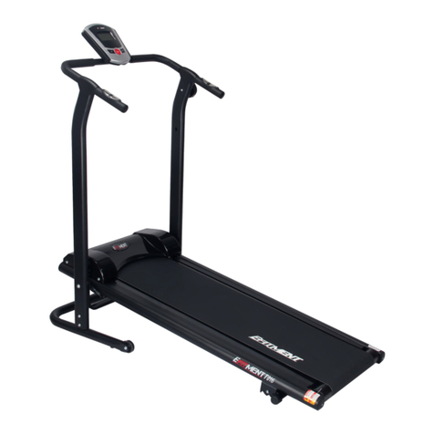
Efitment T017 User manual

2
IMPORTANT SAFETY INSTRUCTIONS
At Efitment your safety is our top priority and to make sure both you and the unit remain in perfect working
order, we encourage you to read all the instructions before assembling and using your new Efitment machine.
Do not skip, substitute or modify any steps or procedures herein, as doing so could result in personal injury and
will void your warranty. DANGER –To reduce the risk of electrical shock, always unplug this unit from its power
source before cleaning or performing any maintenance tasks. WARNING –To reduce the risk of burns, fire,
electric shock, or injury to persons, take the following precautions:
1. Before starting any exercise program you
should consult your physician to determine if
you have any medical or physical conditions
that could put your health and safety at risk or
prevent you from using the equipment
properly. Your physician’s advice is essential if
you are taking any medication that may affect
your heart rate, blood pressure, or cholesterol
level.
2. Be aware of your body’s signals. Incorrect or
excessive exercise can damage your health.
Stop exercising if you experience any of the
following symptoms: pain, tightness in your
chest, irregular heartbeat, shortness of breath,
lightheadedness, dizziness, or feelings of
nausea. If you experience any of these
conditions, you should consult your physician
before continuing with your exercise program.
3. This equipment is intended for adult use only.
Keep children and pets away from the machine.
DO NOT leave children unattended in the same
room with the equipment.
4. Use the equipment on a solid, flat level surface
with a protective cover for your floor or carpet.
To ensure safety, the equipment should have at
least 2 feet of free space all around it.
5. Check if you have all the components and tools
listed. Please note that some components are
pre-assembled to help make the assembly
process quick and easy.
6. Always use the equipment as intended. If you
find any defective components while assembling
or checking the equipment, or if you hear any
unusual noises coming from the equipment
during exercise, discontinue use immediately and
do not use until the problem has been rectified.
7. Always wear appropriate workout clothing when
exercising. Do not wear clothing that can get
tangled in the equipment.
8. Keep hands and other objects away from all
moving parts.
9. The maximum user’s weight is 220 lbs/100 kgs.
10. Be careful when lifting and moving the
equipment. Always use proper lifting technique
and seek assistance if necessary.
11. Your equipment is intended for use in cool, dry
conditions. You should avoid storage in extreme
cold, hot, or damp areas as this may lead to
corrosion and other related problems.
12. This equipment is designed and intended for
indoor use only, not for commercial use.
SAVE THESE INSTRUCTIONS

3
EXPLODED DRAWING

4
PARTS LIST
No.
Description
Qty.
No.
Description
Qty.
1
Main Frame
1
41
Computer
1
2
Bottom Frame
1
42
Plug
4
3
Left Side Hand Post
1
43
Plastic End Cap
2
4
Right Side Hand Post
1
44
Magnet
6
5
Handlebar
1
45
Running Board
1
6
Base of the Magnet
1
46
Running Belt
1
7
Front Roller
1
47
Tension Knob
1
8
Front Axle
1
48L/R
Moving Handlebar
2
9
Rear Roller
1
49
Incline Adjuster
1
10
Rear Axle
1
50
End Cap
2
11
Bolt M6*75L
2
51
Sleeve
2
12
Washer OD13*ID6.2
2
52
End Cap
2
13
Bolt M6*20L
1
53
Moving Handlebar Grip
2
14
Bolt M5*20L
6
54
Screw
4
15
Nut
2
55
Plastic Swing Seat
2
16
Bolt M3*10L
2
A
Bolt M8*15L
6
17a/b
Short Trunk Wire
1
B
Bolt M6*10L
4
18
Bolt M8*45L
1
C
Bolt M8*45L
4
19
Bolt M5*20L
1
D
Bolt M4*12L
2
20
Bolt M6
1
E
Bolt M10*60L
2
21
Bolt M8*40L
2
F
Washer OD16*ID8.3
6
22a/b
Long Trunk Wire
1
G
Arc Washer OD16*ID8.3
4
23
Nut M8
4
H
Washer OD22*ID10.3
2
24
Sensor Wire
1
I
Washer OD12*ID4.2
2
25
Hand Pulse Sensor
2
J
Knob M8*60L
1
26
Pulse Sensor Wire
1
K
Washer OD13*ID6.1
4
27
Bolt M4*20L
2
L
Wrench S5
1
28
Spring
1
M
Wrench S6
1
29
Handle Bar Grip
2
N
Bolt M8X65
2
30
Handle Bar Grip (with hole)
2
O
Sleeve
2
31
Clasp
1
P
Knob
2
32
Rear End Cap
2
Q
Plastic Washer OD60*ID38
4
33
Plastic Washer
4
R
Baffle Plate
1
34
Cover of Handle
2
S
Tension Permanent Seat
1
35
Side Rail
2
T
Steel Wire Cap
1
36
End Cap
2
U
Tension Nut
1
37
Front End Cap
2
V
Tension Bolt
1
38
Plastic Cover
1
W
Tension Nut-2
1
39
Plastic Wheel
2
X
Tension Sleeve
1
40
Base Frame Cushion
6

5
HARDWARE PACKAGE

6
ASSEMBLY INSTRUCTIONS
NOTE: The assembly parts list is included for your reference. Some parts are preassembled on the
machine. In these instances, simply remove and reinstall the parts as required.
STEP 1:
Attach Left & Right Side Hand
Posts (No. 3 & No. 4) to the
Bottom Frame (No. 2) with 6 Bolts
(No. A), 4Washers (No. F) and 2
Arc Washers (No. G), use Wrench
(No. L) to tighten.

7
STEP 2:
Before you assemble the tension cable,
make sure that it is at level 8.
- +
1
2
3
4
5
6
7
8
LOW HIGH
T
E
N
S
I
O
N
C
O
N
T
R
O
L
To assemble the magnetic tension
adjustment mechanism:
1. Insert tension wire into the gap in the
Baffle Plate (No. R), then lower Steel
Wire Cap (No. T) into the hole in Baffle
Plate (No. R). Then insert tension wire
into the gap in Tension Permanent Seat
(No. S), keeping Tension Nut (U)
between Baffle Plate (No. R) and
Tension Permanent Seat (No. S).

8
2. Pull Tension Sleeve (No. X) downward
to bring Baffle Plate (No. R) close to
Tension Permanent Seat (No. S), then
insert Tension Bolt (No. V) into Tension
Permanent Seat (No. S).
3. Turn Tension Nut (No. U) clockwise in
order to tighten Tension Nut (No. U)
and Tension Bolt (No. V) well.

9
STEP 3:
Cover Plastic Cover (No. 38) to the
flywheels of the Main Frame (No. 1) with
4 Bolts (No. B) and 4 Washers (No. K), use
Wrench (No. L) to tighten.
STEP 4:
Stabilize the Left & Right Side Hand Posts
(No. 3 & No. 4), raise and lift the Main
Frame (No. 1) into the Right & Left Side
Hand Posts (No. 3 & No. 4). Ensure the
holes of the Bolt (No. E) and Big Washer
(No. H) are aligned.
Attach Left & Right Side Hand Posts (No. 3
& No. 4) to the Main Frame (No. 1) with 2
Bolts (No. E) and 2 Big Washers (No. H),
use Wrench (No. M) to tighten.
Note: Wait before fully tightening the
bolts.
Connect the Sensor Wire (No. 24) and
Long Trunk Wire (No. 22b).

10
STEP 5:
Attach the Handlebar (No. 5) to the Left &
Right Side Hand Posts (No. 3 & No. 4) with
2 Bolts (No. C) and 2 Arc Washers (No. G),
use Wrench (No. L) to tighten.
Connect the Short Trunk Wire (No. 17b)
and Long Trunk Wire (No. 22a).
Put the 2 Covers of Handle (No. 34) on the
Handlebar (No. 5).
Now fully tighten all Bolts (No. E)
assembled in Step 4 that connect the Main
Frame (No. 1) to the Left & Right Side
Hand Posts (No. 3 & No. 4), use Wrench
(No. M) to tighten.
STEP 6:
Remove 2 Bolts (No. D) and 2 Washer (No.
I) from back of the Computer (No. 41).
Attach the Computer (No. 41) to the
Handlebar (No. 5). Connect the Short
Trunk Wire (No. 17a) and the wire of the
Computer (No. 41). Insert the Pulse
Sensor Wire (No. 26) into the back PULSE
hole of the Computer (No. 41). Then
secure 2 Bolts (No. D) and 2 Washers (No.
I) using a Wrench (No. L).

11
STEP 7:
The 4 Plastic Washers (No. Q) are bound
with the 2 Plastic Swing Seats (No. 55).
Cut the straps and remove 4 Plastic
Washers (No. Q) from the 2 Plastic Swing
Seats (No. 55).
Attach the Moving Handlebars (No. 48L/R)
with 4 Plastic Washers (No. Q) on both
sides of the Plastic Swing Seats (No.55) to
Right & Left Side Hand Posts (No. 3 & No.
4) with 2 Bolts (No. N), 2 Washer (No. F), 2
Sleeves (No. O), and 2 Knob (No. P).
Insert and tighten the Knob (No. J) into the
bottom hole of the Right Side Hand Post
(No. 4).
Assembly is now complete!
IMPORTANT NOTE!
You will need to lubricate your
treadmill before the first use.
See Page 12.

12
LUBRICATING THE TREADMILL
*IMPORTANT NOTE:
You will need to lubricate your treadmill before the first use.
Lubricating the Running Board (No.45) and Running Belt (No. 46) is essential as the friction
between the two affects the life span and function of the treadmill. Inspect the Running Board (No.
45) and Running Belt (No. 46) regularly. Should you find any wear on the Running Board (No. 45),
please contact us at: service@zoovaa.com.
WARNING: Always unplug the treadmill from the electrical outlet before cleaning, lubricating or
repairing the unit.
HOW TO LUBRICATE:
1. Raise the Running Belt (No. 46) up on one side and apply lubricant to the Running Board (No.
45). Use a rag to thoroughly wipe the lubricant over the Running Board (No. 45). Repeat this
process for the other side.
2. The moving parts should turn freely and quietly. Abnormality of moving parts will affect the safety of
the equipment. Inspect and tighten bolts regularly.
3. To better maintain the treadmill and prolong its lifespan, it is suggested that maintenance be done
on a regular basis.
4. DO NOT LOOSEN OR MAKE ANY ADJUSTMENT TO THE RUNNING BELT WHILE APPLYING
LUBRICANT. A loose Running Belt (No. 46) will result in the runner sliding off during use, while
too tight of a Running Belt (No. 46) will negatively affect the motor’s performance and also create
more friction between the roller and Running Belt (No. 46). The most suitable tightness for the
Running Belt (No. 46) is when it is pulled out 50-75mm from the Running Board (No. 45).
The following time table is recommended:
Light user (less than 3 hours/ week) every five months
Medium user (4-7 hours/ week) every two months
Heavy user (more than 7 hours/ week) every one months

13
ADJUSTING THE INCLINE
There are 3 incline angles (A: 7°, B: 8°, C: 9°).
To adjust the incline, lift the rear end of the main frame up, and use your other hand to adjust
the incline adjuster to the desired position.
NOTE: Always use proper lifting technique to prevent injury.

14
FOLDING
ADJUSTING THE BELT
If the Running Belt (No. 46) is not centered
correctly, the treadmill will be noisy.
If the Running Belt (No. 46) is too tight, too
loose or not centered, use the Wrench (No.
L) to adjust it.
1. If the Running Belt (No. 46) drifts to the
right, turn the right Bolt (No. 11) 1 or 2
turns clockwise.
2. If the Running Belt (No. 46) drifts to the
left, turn the left Bolt (No. 11) 1 or 2
turns counter-clockwise.
3. If the Running Belt (No. 46) is too tight,
turn the left and right Bolts (No. 11)
counter-clockwise.
4. If the Running Belt (No. 46) is too loose,
turn the left and right Bolts (No. 11)
clockwise.
Before folding, completely loosen Knob (No.
J) from the bottom hole A in the Bottom
Frame (No. 2). Lift Main Frame (No. 1) to the
upright position, then insert and tighten Knob
(No. J) to the upper hole B.

15
ADJUSTING THE TENSION
.
The user can set the desired tension
according to the picture showing:
To decrease the tension, loose the Bolt (No.
20) counter-clockwise, turn the Bolt (No. 13)
clockwise, then tighten the Bolt (No. 20)
clockwise.
To increase the tension, loose the Bolt (No.
20) clockwise, turn Bolt (No. 13) counter-
clockwise, then tighten the Bolt (No. 20)
counter-clockwise.
After adjusting the Bolt (No. 13), check if the
tension wire is too loose. If necessary, adjust
the Tension Nut (No. U) or Tension Nut-2
(No. W) on the tension wire.
Up the Tension Nut (No. U) counter-
clockwise. Up the Tension Nut-2 (No. W)
clockwise, then down the Tension Nut (No.
U) clockwise to tighten.

16
ADJUSTING THE TENSION OF THE MOVING HANDLEBARS
This treadmill has Moving Handlebars (No.
48L/R) that let you exercise your arms and
upper body. Use the Moving Handlebars (No.
48L/R) as shown in the picture. You can
exercise with just the Moving Handlebars
(No. 48L/R) or use them while walking on the
treadmill.
Use Knob (No. P) to adjust the tension of the
Moving Handlebars (No. 48L/R). Turn
clockwise to increase tension. Turn counter-
clockwise to decrease tension

17
HOW TO MOVE THE TREADMILL
Before attempting to move the treadmill,
please make sure that it has been properly
folded. The Knob (No. J) must be tightened.
Start by placing two hands at Hand Pulse
Sensors (No. 25) to support the treadmill.
Next, please place one foot at Plastic Wheel
(No. 39) to hold the bottom end of the
treadmill steady. With your foot at Plastic
Wheel (No. 39), slowly tilt the top of the
treadmill downward towards the ground.
Once the Main Frame (No. 1) reaches a
certain point, the Plastic Wheels (No. 39) of
treadmill will touch the ground.
To transport, hold the treadmill at Hand
Pulse Sensors (No. 25) and tilt until the
Plastic Wheels (No. 39) are able to move on
the ground.

18
TIME………………………………………………….……....................................………………..….00:00-99:59 MIN
SPEED…………………………………………………..................................................................0.0-99.99 MPH
DISTANCE……………………………………………….…...............................................................0.0-999.9 MI
CALORIE……………………………………………………….........................................................0.0-999.9 KCAL
ODOMETER………………………………………………………………………………….…………………………….0-9999 MI
PULSE………………………………………………….......................................................................40-220 BPM
The display will turn on when you start walking on the treadmill or when you press the button
After 4-5 minutes of inactivity, the display will shut off automatically. When the treadmill is
not moving, computer will display STOP on the side.
MODE: Press to select and set to a function. Hold for 2 seconds to reset the computer. The
data for all functions will be cleared.
SET: Under STOP condition, press to set the value of TIME, DISTANCE, CALORIES or PULSE. You
can hold the button for seconds to increase the data.
RESET: Press to reset each function: Time, Distance, Calorie, Pulse. Hold for 2 seconds to reset
the computer. The data for all functions will be cleared.
(When you replace the batteries, all the values will reset to ZERO automatically.)
HOW TO SELECT A FUNCTION:
Press MODE to SCAN. To set a function, press MODE button when the pointer is on the
function you want and the function starts blinking.
FUNCTIONS:
1. TIME: Press the MODE button until pointer is set to TIME. The total working time will be
shown.
2. SPEED: Press the MODE button until pointer is set to SPEED. The current speed will be
shown.
3. DISTANCE: Press the MODE button until pointer is set to DISTANCE. The distance of each
workout will be displayed.
4. CALORIE: Press the MODE button until pointer is set to CALORIE. The calories burned will be
displayed.
5. ODOMETER: Press the MODE button until pointer is set to ODOMETER. The displays
accumulative distance from combined exercise sessions.
6. PULSE: Press the MODE button until the pointer it set to PULSE function and hold the pulse
sensor for about 3 seconds to measure pulse.
OPERATING INSTRUCTIONS

19
COUNTDOWN FUNCTION:
Under STOP condition, press SET button to set Time, Distance or Calorie to countdown. Once
the data goes to zero, the computer will beep. That means countdown function ends, and the
data starts counting from “1”. You can set the Countdown function only when the treadmill is
stopped.
SCAN: Displays each function for 4 seconds in the following sequence:
TIME—SPEED—DISTANCE—CALORIE—ODOMETER—PULSE
BATTERY: The computer uses 2 PCS 1.5V AA batteries., which are included. If there is a
problem with the display, try changing the batteries first. When changing the batteries,
change both of them. Do not mix old and new batteries. Do not mix battery types. Dispose
old batteries according to your regional guidelines.
V3

20
Other manuals for T017
1
Table of contents
Other Efitment Treadmill manuals

