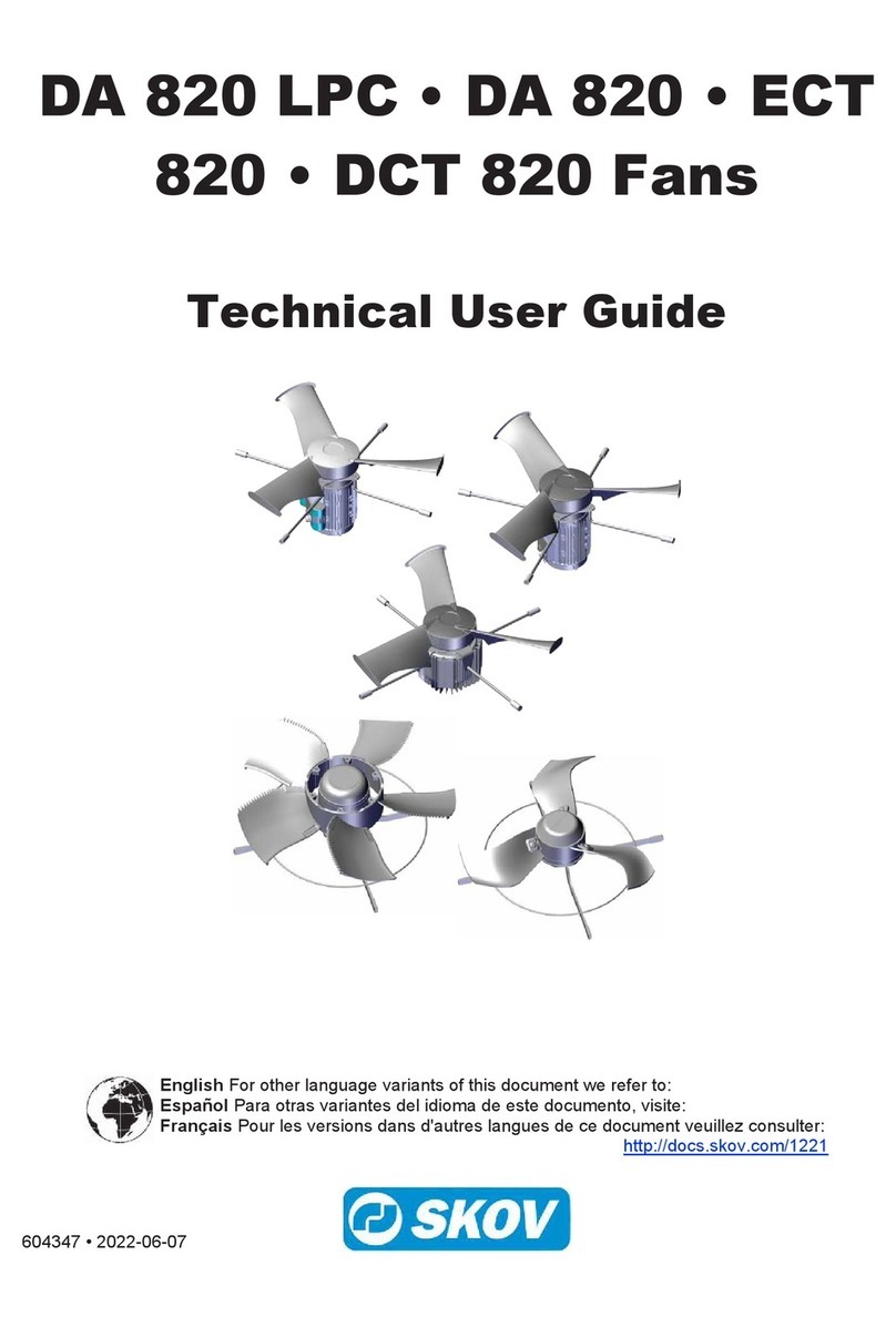
Skov BF 50 Manual

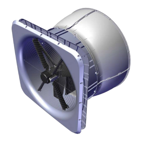
BF 50 Recirculation
Technical User Guide
604435 • 2023-01-24
English For other language variants of this document we refer to:
Español Para otras variantes del idioma de este documento, visite:
Français Pour les versions dans d'autres langues de ce document veuillez consulter:
http://docs.skov.com/1241


BF 50 Recirculation
Technical User Guide 3
Product and Documentation Changes
SKOV A/S reserves the right to change this document and the product herein described without further notice.
In case of doubt, please contact SKOV A/S.
The date of change appears from the front and back pages.
IMPORTANT
Notes concerning alarm systems
Breakdowns, malfunctions or faulty settings may cause substantial damage and financial losses when regulat-
ing and controlling the climate in a livestock house. It is therefore essential to install a separate, independent
alarm system that monitors the house climate concurrently with the climate and production controller. According
to EU-directive No. 98/58/EU, an alarm system must be installed in all mechanically ventilated houses.
We would like to draw your attention to the fact that the product liability clause of general terms and conditions
of sale and delivery specifies that an alarm system must be installed.
Note
• All rights belong to SKOV A/S. No part of this manual may be reproduced in any manner whatsoever without
the expressed written permission of SKOV A/S in each case.
• All reasonable efforts have been made to ensure the accuracy of the information contained in this manual.
Should any mistakes or imprecise information occur in spite of this, SKOV A/S would appreciate being noti-
fied thereof.
• Irrespective of the above, SKOV A/S shall not accept any liability with regard to loss or damage caused or
alleged to be caused by reliance on any information contained herein.
• Copyright by SKOV A/S.

BF 50 Recirculation
Technical User Guide
1 Product description ....................................................................................................................................... 6
2 Product survey ............................................................................................................................................... 7
2.1 BF 50 recirculation fan ............................................................................................................. 7
2.1.1 Type key ...................................................................................................................................... 7
2.2 Accessories................................................................................................................................ 9
3 Mounting guide............................................................................................................................................. 11
3.1 Recommended tools................................................................................................................ 11
3.2 Removal of transport bracket ................................................................................................. 12
3.3 Mounting of accessories......................................................................................................... 13
3.3.1 Mounting of bracket for recirculation.......................................................................................... 13
3.3.2 Mounting of inside safety net ..................................................................................................... 14
3.3.3 Mounting of outside safety net ................................................................................................... 15
4 Installation guide.......................................................................................................................................... 16
4.1 Electrical connection............................................................................................................... 16
4.1.1 Disclaimer at retrofitting fans ..................................................................................................... 16
4.1.2 cUL............................................................................................................................................. 16
4.1.3 Mains supply dimensioning regarding harmonic distortion ........................................................ 16
4.1.4 Cabling to connection box and LPC motor controller................................................................. 17
4.1.5 Cabeling and placement of LPC motor controller ...................................................................... 17
4.2 Connection in the LPC motor controller/frequency converter ............................................ 18
4.2.1 Terminals for power supply........................................................................................................ 19
4.2.2 Terminals for supply of the fan motor ........................................................................................ 20
4.2.3 Signal terminals ......................................................................................................................... 20
4.2.4 Terminals on relay module (accessories) .................................................................................. 20
4.3 LED indication on the motor controller/frequency converter.............................................. 21
4.4 Alarms....................................................................................................................................... 21
4.5 General information about circuit diagrams ......................................................................... 22
4.5.1 Color code.................................................................................................................................. 22
4.5.2 Power supply isolator................................................................................................................. 22
4.5.3 Letter code ................................................................................................................................. 22
4.6 Cable plans and circuit diagrams........................................................................................... 23
4.6.1 BF 50 LPC recirculation 1x230 V .............................................................................................. 23
4.6.1.1 Cable plan.................................................................................................................................. 23
4.6.1.2 Terminals in LPC 1x230 V fan ................................................................................................... 23
4.6.1.3 Circuit diagram........................................................................................................................... 24
4.6.2 BF 50 LPC recirculation 3x400 V .............................................................................................. 25
4.6.2.1 Cable plan.................................................................................................................................. 25
4.6.2.2 Terminals in LPC 3x400 V fan ................................................................................................... 25
4.6.2.3 Circuit diagram........................................................................................................................... 26
4.6.3 BF 50 ON/OFF recirculation 1x230 V ....................................................................................... 27
4.6.3.1 Cable plan.................................................................................................................................. 27
4.6.3.2 Terminals in ON/OFF 1 x 230 V fan........................................................................................... 27
4.6.3.3 Circuit diagram........................................................................................................................... 28
4.6.4 BF 50 ON/OFF recirculation 3x400 V ....................................................................................... 29
4.6.4.1 Cable plan.................................................................................................................................. 29
4.6.4.2 Terminals in ON/OFF 3x400 V fan............................................................................................. 29
4.6.4.3 Circuit diagram........................................................................................................................... 30
4.6.5 BF 50 ON/OFF recirculation 3x230 V ....................................................................................... 31
4.6.5.1 Cable plan.................................................................................................................................. 31
4.6.5.2 Terminals in ON/OFF 3x230 V fan............................................................................................. 31
4.6.5.3 Circuit Diagram .......................................................................................................................... 32
5 Maintenance instructions ............................................................................................................................ 33
5.1 Cleaning.................................................................................................................................... 33
5.1.1 Fan............................................................................................................................................. 33

BF 50 Recirculation
5.1.2 Motor controller/frequency converter ......................................................................................... 33
5.2 Recycling/Disposal .................................................................................................................. 33
6 Troubleshooting ........................................................................................................................................... 34
7 Technical data .............................................................................................................................................. 36
7.1 BF 50 LPC recirculation 1x230 V ........................................................................................... 36
7.2 BF 50 LPC recirculation 3x400 V ........................................................................................... 38
7.3 BF 50 ON/OFF recirculation 1x230 V ..................................................................................... 40
7.4 BF 50 ON/OFF recirculation 3x400 V ..................................................................................... 41
7.5 BF 50 ON/OFF recirculation 3x230 V ..................................................................................... 42
7.6 Dimensioned sketch ................................................................................................................ 43
7.6.1 BF 50 recirculation ..................................................................................................................... 43
7.6.2 Outside safety net ...................................................................................................................... 43
7.6.3 LPC motor controller .................................................................................................................. 44
Technical User Guide

BF 50 Recirculation
6 Technical User Guide
1 Product description
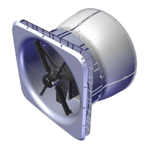
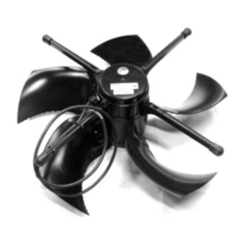
BF 50 recirculation is a direct-driven corrosion-resistant recirculation fan.
BF 50 recirculation is supplied without safety net - these can be ordered as accessories.
The recirculation fan is available in several different versions focusing on low power consumption, as well as
standard versions.
BF 50 is specially designed for harsh livestock house environments. This applies to both climatic and electrical
influences.

BF 50 Recirculation
Technical User Guide 7
2 Product survey
2.1 BF 50 recirculation fan
2.1.1 Type key
BF 50 ON/OFF recirc. 400V3 50Hz 1.5hp
Fan name
BFBlue fan
Fan size
Impeller diameter in inches” 50
Fan type
AC fan
LPC fan
ON/OFF
LPC
Rated voltage
3x400 V AC
3x230 V AC
1x230 V AC
400V3
230V3
230V1
Supply frequency
50 Hz and 60 Hz
50 Hz
60 Hz
50/60Hz
50Hz
60Hz
Horsepower / motor performance
hp
1.5

BF 50 Recirculation
8 Technical User Guide
435453 BF 50 LPC recirc. LE 230V1 50/60Hz
Safety net must be mounted to comply with CE marking, in countries where
this is required.
LPC motor controller
PM motor 1.5 kW.
0.7 m motor cable.
Is supplied assembled without net.
ErP 2015 approved.
435454 BF 50 LPC recirc. LE 400V3 50/60Hz
Safety net must be mounted to comply with CE marking, in countries where
this is required.
LPC motor controller
PM motor 1.5 kW.
0.7 m motor cable.
Is supplied assembled without net.
ErP 2015 approved.
435450 BF 50 ON/OFF recirc. 230V1 1.5hp 50Hz
435451 BF 50 ON/OFF recirc. 230V1 1.5hp 60Hz
Safety net must be mounted to comply with CE marking, in countries where
this is required.
AC motor 1x230 V 1.2 kW.
0.7 m motor cable.
Is supplied assembled without net.
ErP 2015 approved.
435452 BF 50 ON/OFF recirc. 400V3 1.5hp 50Hz
Safety net must be mounted to comply with CE marking, in countries where
this is required.
AC motor 3x400 V 1.2 kW.
0.7 m motor cable.
Is supplied assembled without net.
ErP 2015 approved.

BF 50 Recirculation
Technical User Guide 9
435448 BF 50 ON/OFF recirc. 230V3 1.5hp 60Hz
Safety net must be mounted to comply with CE marking, in countries where
this is required.
AC motor 3x230 V 1.2 kW.
0.7 m motor cable.
Is supplied assembled without net.
ErP 2015 approved.
2.2 Accessories
435460 BF 50 mounting brackets f/recirculation
The mounting bracket is used for recirculation where the fan hangs from the
ceiling.
Supplied with screws for mounting on the fan. SKOV A/S do not supply
other mounting parts.
One for each fan.
435437 BF 50 safety net kit inside
The safety net kit inside is used on BF 50 where extra safety is required.
Supplied with mounting parts.
One for each fan.
435397 BF 50 safety net outside wo/cone, A2
435398 BF 50 safety net outside wo/cone, galv
The outside safety net is used on BF 50 without cone where extra safety is
required.
Supplied with mounting parts.
One for each fan.

BF 50 Recirculation
10 Technical User Guide
445076 LPC-2 relay module
Used for mounting in motor controller/frequency converter, if an alarm out-
put is required or reversing of fan is required.
1 x potential free output relay 1 A, 30 V DC/24 V AC.
1 x digital input.
435490 BF 50/BF 55/DA 1700 PM motor cable 4-core 4 m
Is used for LPC fans in cases where 0.7 m motor cable from the fan box is
insufficient.
After replacing the existing motor cable for BF 50/BF 55/DA 1700 PM motor
cable 4-core 4 m, the motor cable out of the fan box will be 2.7 m.

BF 50 Recirculation
Technical User Guide 11
3 Mounting guide
3.1 Recommended tools
A list of the recommended tools for mounting purposes can be seen below.
Item Description
Cordless drill
Screwdriver bits
Drill kit
Utility knife
Marker pen
Torque wrench
Tape measure
Combination spanner kit
Screwdriver
Ladder
Multigrip pliers
Spirit level
Try square
2 men

BF 50 Recirculation
12 Technical User Guide
3.2 Removal of transport bracket
On the recirculation fan the red transport bracket is
placed between the impeller and the center pillar.
Twist the transport bracket out from the center pillar.
Remove transport brackets from the fan.

BF 50 Recirculation
Technical User Guide 13
3.3 Mounting of accessories
3.3.1 Mounting of bracket for recirculation
Place the 4 brackets as shown. The two brackets that
are similar must be placed diagonally.
Mark 6 holes for each of the 4 brackets.
Pre-drill the 6 holes with a Ø4.8 mm drill.
Mount the 4 bracket on the recirculation fan using the 6
6x20 screws provided (do not tighten to more than 2
Nm).
When choosing suspension.
Please note that the recirculation fan weighs 72 kg.

BF 50 Recirculation
14 Technical User Guide
3.3.2 Mounting of inside safety net
If a safety net has not been selected, a safety guard must be established. The requirements of the International
Standard for Safety of machinery ISO 13857 shall be complied with.
Make sure that the net is turned as shown in the draw-
ing.
Mount the inside safety net on the fan using 8 of the
screws enclosed (do not tighten to more than 2 Nm).
Mount the enclosed 4 straps and screws.
Guide the strap around the net.
Mount the screws (do not tighten to more than 2 Nm).

BF 50 Recirculation
Technical User Guide 15
3.3.3 Mounting of outside safety net
If a safety net has not been selected, a safety guard must be established. The requirements of the International
Standard for Safety of machinery ISO 13857 shall be complied with.
Assemble the safety net outside with the included strips.
Mount 2 strips in all corners.
Mount the safety net outside on the fan using the screws
enclosed (do not tighten to more than 2 Nm).

BF 50 Recirculation
16 Technical User Guide
4 Installation guide
4.1 Electrical connection
Installation, servicing and troubleshooting of all electrical equipment must be carried out by quali-
fied personnel in compliance with the applicable national and international standard EN 60204-1
and any other EU standards that are applicable in Europe.
The installation of a power supply isolator is required for each motor and power supply to facilitate
voltage-free work on the electrical equipment. The power supply isolator is not included.
4.1.1 Disclaimer at retrofitting fans
In the case of retrofitting fans in an existing house, regardless of ON/OFF fans, LPC fans or frequency convert-
ers SKOV recommends that a local expert is involved in checking the electrical installations. The focus should
be on cable dimensions, overload protections, local transformers, etc. It is of outmost importance to take the fan
specifications into account and, at the same time, ensure that local requirements are fulfilled.
4.1.2 cUL
Overcurrent protection provide overload protection to avoid overheating of the cables in the installation. Over-
current protection must always be carried out according to local and national regulations. Suitable for use on a
circuit capable of delivering not more than 5,000 rms symmetrical amperes, 480 V maximum. Circuit breakers
must be designed for protection in a circuit capable of supplying a maximum of 10,000 Arms (symmetrical), 480
V maximum; or the value rated on the individual circuit breaker.
For UL Compliance Use the breakers or fuses listed below in the table to ensure compliance with UL or IEC
61800-5-1. Circuit breakers must be designed for protection in a circuit capable of supplying a maximum of
10,000 Arms (symmetrical), 480 V maximum. In the event of malfunction, failure to follow the protection recom-
mendation may result in damage to the drive / frequency converter. Circuit breaker must comply with UL 489.
Input voltage
Nominal
[V]
Input voltage
Voltage range
[V]
Controller type Circuit breaker UL recommended
MCCB
Fuse UL recom-
mended
Recommended
by UL
[A]
Max. UL
[A]
Type: RK5, RK1,
J,T or CC
[A]
1x230 207 - 256 BF 50 LPC 10 35 15
3x400 360 - 440 BF 50 LPC 4 15 6
3x230 207 - 256 BF 50 LPC 8 25 15
4.1.3 Mains supply dimensioning regarding harmonic distortion
LPC motor controllers and frequency converters function like any other electronic power converter by converting
AC to DC. As this conversion produces a non-sinusoidal current, the mains supply for the controller is affected
by harmonic distortion.
The electrician or the user of the equipment must ensure, possibly through contact with the supply company,
that the equipment is connected to a properly sized mains supply.

BF 50 Recirculation
Technical User Guide 17
4.1.4 Cabling to connection box and LPC motor controller
LPC motor controller
Power supply isolator
Connection box
Example of cabling to connection box and LPC motor
controller.
4.1.5 Cabeling and placement of LPC motor controller
Motor controller must not be built-in or covered and
must be mounted on a solid, level surface.
In order to uphold protection classifications, ensure ac-
cess of cables and cooling of the motor controller, the
distances to the surroundings of 150 mm must be ad-
hered to.
In order to prevent water from running into the motor
controller via cables and screwed connections, the ca-
bling must be carried out so that it can stand water
around the cable in the gasket of the screwed connec-
tion.

BF 50 Recirculation
18 Technical User Guide
4.2 Connection in the LPC motor controller/frequency converter
1Motor connection terminals (U, V, W, PE)
2Connection terminals for braking resistor (not used)
3Connector for optional module
4Terminal block for programming interface
5RJ12 programming connector (2 x slave / 1 x master)
63-point strain relief for modbus cable
7Power supply terminals for 1-phase (L, N, PE) and 3-phase (L1, L2, L3, N, PE)

BF 50 Recirculation
Technical User Guide 19
4.2.1 Terminals for power supply
Power supply 3 x 400 V / 3 x 230 V.
Power supply 1 x 230 V.

BF 50 Recirculation
20 Technical User Guide
4.2.2 Terminals for supply of the fan motor
Remember to strip the cable so that the protective shield
from the fan can be connected to the motor controller
during mounting under the rail.
Connection from motor controller to fan motor.
4.2.3 Signal terminals
Not in use
Not in use
Ground
Not in use
Signal from controller
Ground
10-0 V = open
0-10 V = GND (Short-circuit connection between terminal 7 and
GND)
Stop = open
Start = GND (Short-circuit connection between terminal 8 and
GND)
Not in use
Ground
4.2.4 Terminals on relay module (accessories)
Relay module 445076 can be purchased as accessories.
Alarm NO
Max. 30 V DC / 24 V AC
Alarm NC
Other manuals for BF 50
2
Table of contents
Other Skov Fan manuals