EGAmaster 57520 User manual

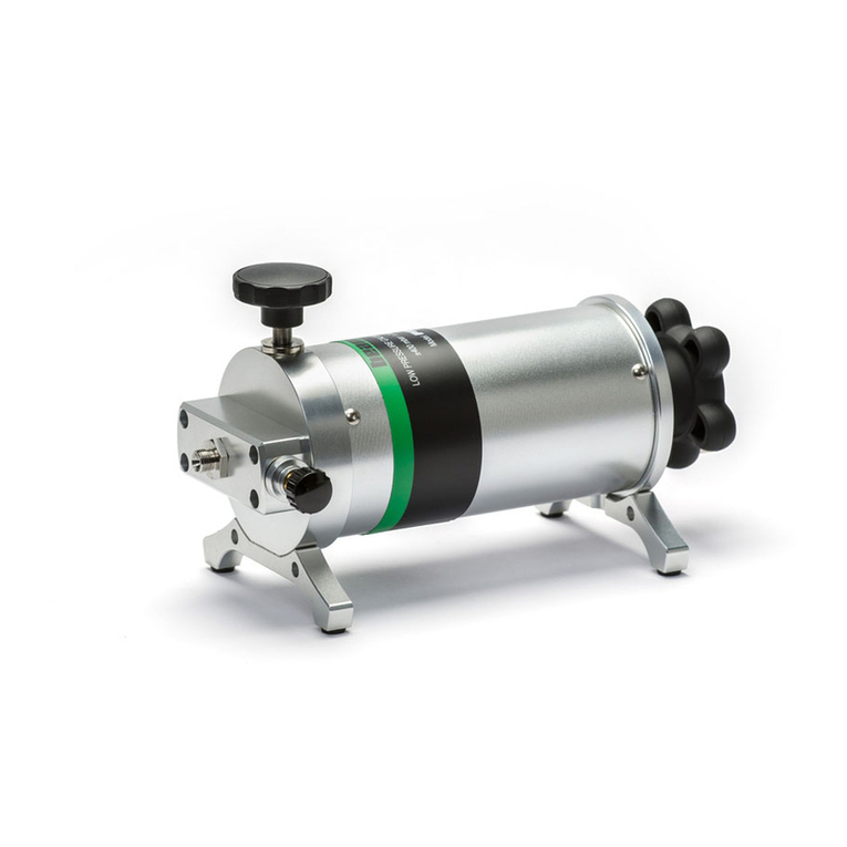
BOMBA HIDRÁULICA MANUAL
MANUAL HYDRAULIC PUMP
MANUAL DE INSTRUCCIONES
OPERATING INSTRUCTIONS
ESPAÑOL ............................... 2
ENGLISH................................ 5
GARANTIA / GUARANTEE..... 9
COD.57520
COD.57521

2
INSTRUCCIONES DE SEGURIDAD
¡Advertencia!
1. La presión creada con la máquina puede causar daños.
2. Respete las instrucciones generales de seguridad, utilice zapatos y gafas de seguridad.
3. Compruebe que las mangueras de presión no estén dañadas y que estén libres de cualquier
obstrucción: si es necesario, sustitúyalas por piezas originales.
4. En caso de no utilizar la máquina por un período prolongado y/o en países de bajas
temperaturas, introduzca un poco de solución anti-congelante dentro de la máquina. Esto
alargará la vida de las juntas.
CARACTERÍSTICAS TÉCNICAS
COD Tipo de
bomba
Desplazamiento del
pistón por bombeo
(cm3)
Fuerza
máxima de
bombeo
(kg)
Capacidad
de aceite
(cm3)
Peso con
aceite (kg)
1ª Etapa 2ª Etapa
57520 2-VELO 13 2.2 35 700 10
57521 13 2.3 35 2700 14
INSTRUCCIONES DE USO
Antes de empezar cualquier trabajo, compruebe la integridad de todos los componentes.
1. Compruebe el nivel de aceite del depósito. Si es necesario, añada aceite.
2. Compruebe todas las conexiones para asegurar que no existan fugas.
NOTA: No ponga la bomba en funcionamiento si el tapón de aceite no está colocado
perfectamente. Así se evitará que entre polvo o partículas que puedan dañar el sistema.
PRECAUCIÓN: Realice una presión suave y uniforme sobre la palanca para evitar
deformaciones en la misma o una sobrepresión en el sistema.
3. Conecte la manguera al equipo hidráulico que se vaya a utilizar.
ESPAÑOL

3
4. Cierre la válvula de descarga con la mano, sin apretar con fuerza, en el sentido de las agujas
del reloj hasta el nal.
5. Bombee la palanca de accionamiento para suministrar aceite al sistema. La bomba dispone
de una válvula interna de seguridad que actuará cuándo se llegue a la presión máxima
permitida, 700bar. De esta forma se obtendrá un buen funcionamiento del sistema y la
ausencia de fugas de aceite.
6. Abra la válvula de descarga del sistema en el sentido contrario de las agujas del reloj para
liberar la presión del sistema.
Palanca de
accionamiento
Tapón de llenado
de aceite
Válvula de descarga
Manguera
MANTENIMIENTO
• Compruebe el nivel de aceite ocasionalmente y añada aceite si fuera necesario. Es
importante utilizar aceite hidráulico. No utilizar otro tipo de aceite.
Comprobación del nivel de aceite:
1. Coloque la bomba en posición horizontal.
2. Retire el tapón de llenado de aceite y compruebe el nivel de aceite.
3. Si el nivel de aceite es bajo, añada aceite a través del tapón de llenado. Para ello se
aconseja retroceder completamente el pistón (abrir válvula de descarga).
4. Vuelva a colocar el tapón de llenado de aceite y asegúrese de que está bien apretado.
• Para prolongar la vida del equipo, limpie y engrase la articulación de la palanca de
accionamiento y la rosca del cilindro.

4
SOLUCIÓN A POSIBLES ERRORES
a) El pistón no avanza:
- Cierre completamente la válvula de descarga.
- Compruebe el nivel de aceite.
b) No hay presión en el sistema:
- Compruebe que no existan fugas o que las conexiones estén perfectamente apretadas.
c) El pistón no retrocede o no retrocede completamente:
- Abra la válvula de descarga.
- Compruebe el nivel de aceite. Retire aceite si hay exceso dentro del sistema.
NOTAS
¡IMPORTANTE!
El fabricante no se responsabiliza de los daños o mal funcionamiento de la máquina en
caso de que no se use correctamente o se haya utilizado para trabajos para los que no está
diseñada.
GARANTÍA
El fabricante garantiza al comprador de ésta máquina la garantía total durante 12 meses de
las piezas con defectos de fabricación.
Esta garantía no cubre aquellas piezas que por su uso normal tienen un desgaste.
Nota: para obtener la validez de la garantía, es absolutamente imprescindible que
complete y remita al fabricante el documento de “CERTIFICADO DE GARANTIA”, dentro
de los siete dias a partir de la fecha de compra.

5
SAFETY INSTRUCTIONS
Warning!
1. The pressure created in the machine can cause damage.
2. Respect the general safety instructions, wear shoes and goggles.
3. Check that pressure hoses are not damaged and there are free of any obstruction: if
necessary, replace them with original parts.
4. In case of not using the machine for an extended period or in countries of low temperatures,
insert some antifreeze solution inside the machine. This will prolong the life of the seals.
TECHNICAL SPECIFICATIONS
COD Bomb type Displacement per
stroke (cm3)Max.
Pumping
force (kg)
Oil
capacity
(cm3)
Weight
(kg)
1ª Stage 2ª Stage
57520 2-VELO 13 2.2 35 700 10
57521 13 2.3 35 2700 14
GUIDE OF USAGE
Before starting work, check the integrity of all components.
1. Check the oil level in the tank. If necessary, add oil.
2. Check all connections to ensure there are no leaks.
NOTE: Do not start the pump if the oil cap is not positioned perfectly. Thus, particles or dust
will not enter the system.
ENGLISH

6
CAUTION: Make a gentle pressure and uniform on the lever to prevent deformations or an
overpressure in the system.
3. Connect the hose to hydraulic machine to be used.
4. Close the external drain valve with the hand, loosely hard, in clockwise direction.
5. Pump the lever for supplying oil to the system. The pump has an internal safety valve that it
will act when it reaches the maximum allowable pressure, 700bar. Thus, it will have a good
operation of the system and there will be no oil leakage.
6. Open the external drain valve in anticlockwise direction to release the pressure of the system.
Lever
Oil cap
Drain valve
Hose
MAINTENANCE
• Check the oil level occasionally and add oil if necessary. It is very important use hydraulic
oil. Do not use other types of oil.
• Checking the oil level:
1. Putt he pump in a horizontal position.
2. Remove the oil cap and check the oil level.
3. If the oil level is low, add oil to the system. It is advisable to go back the piston completely
(open the external drain valve).
4. Put the oil cap and make sure that it is tight.
• Clean and lubricate the joint of the lever and the screw of the cylinder to prolong the life
of the equipment.
SOLUTION TO POSSIBLE MALFUNCTION
a) The piston does not advance:
- Close the external drain valve completely.
- Check the oil level.

7
b) There is no pressure in the system:
- Check for leaks or the connections are tight perfectly.
c) The piston does not go backwards or it does not go backwards completely.
- Open the external drain valve.
- Check the level oil. Remove oil if there is a lot inside the system.
NOTES
IMPORTANT!
The maker will not take responsibility for damage or malfunction as a result of the poduct
being incorrectly used or, applied for a purpose for which it was not intended.
GUARANTEE
The maker guarantees to the machine owner 12 months against any manufacture defect.
This guarantee does not cover the parts wich are consumables.
Note: to apply the guarantee it is necesary to send the “GUARANTEE CERTIFICATE” duly
lled within one week after purchased the machine to the maker.

8


This manual suits for next models
1
Table of contents
Languages:
Other EGAmaster Water Pump manuals
Popular Water Pump manuals by other brands
KoiPro
KoiPro Air-Blow User instructions
Zoeller
Zoeller QWIK JON ULTIMA 202 Series installation instructions

Flotec
Flotec E50TLT owner's manual
Trixie
Trixie 86300 Instructions for use

Doheny's
Doheny's 90500 Installation, operation & parts
Grundfos
Grundfos Unilift AP Installation and operating instructions

Wigam
Wigam P2 Series User and service manual

JEC Pumps
JEC Pumps JRZS Series operating & maintenance manual
GORMAN-RUPP
GORMAN-RUPP 2P5X Specifications information and repair parts manual

BUSCH
BUSCH MINK MV 0312 B instruction manual
Pentair
Pentair MYERS MCI033 owner's manual
Draper
Draper SWP110ADW instructions


