eGauge Systems LLC EDC User manual


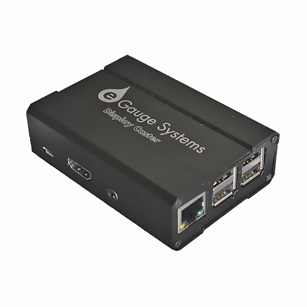
eGauge Display Caster
The eGauge Display Caster provides an easy method display an eGauge meter device interface on
a TV or monitor via HDMI through an easy-to-use interface.
The Display Caster has a micro USB input for power, USB inputs for keyboard and mouse for initial
configuration, and an HDMI output to connect to a TV or monitor. Network/internet connection can
be obtained through built-in 2.4GHz WiFi or an Ethernet-direct connection.
Once the Display Caster is configured, the saved eGauge device interface will be displayed after
automatically recovering from a power outage or communication loss.
Micro-USB powered
USB for keyboard and mouse
HDMI output
2.4GHz b/g/n
eGauge Display Caster
Micro-USB to USB-A for power
120V to Mini-USB power adapter for power
eGauge Display Caster
Visit the online store page
Model: EDC
Specifications
Hardware included

HDMI cable
Printed Manual
Velcro for mounting
1. Connect keyboard and mouse via USB
2. Connect HDMI to television or monitor
3. Apply power using 120V to 5V USB supply, or micro-USB cable
4. Configure network, timezone, and device to display and save as default (see Display
Caster Manual for software setup information).
Ensure timezone is set correctly
Ensure default kiosk is saved
Follow the Display Caster Manual for software setup.
To factory reset - connect a keyboard and press Ctrl+Shift+J simultaneously.
Assembly/installation information
The default password for the display caster is printed on the paper attached to the manual,
as well as inside the box with the eGauge Display Caster. The password can be changed
during setup.
Do not leave keyboard/mouse, or USB ports accessible in public kiosk display
Software configuration Information
Documents


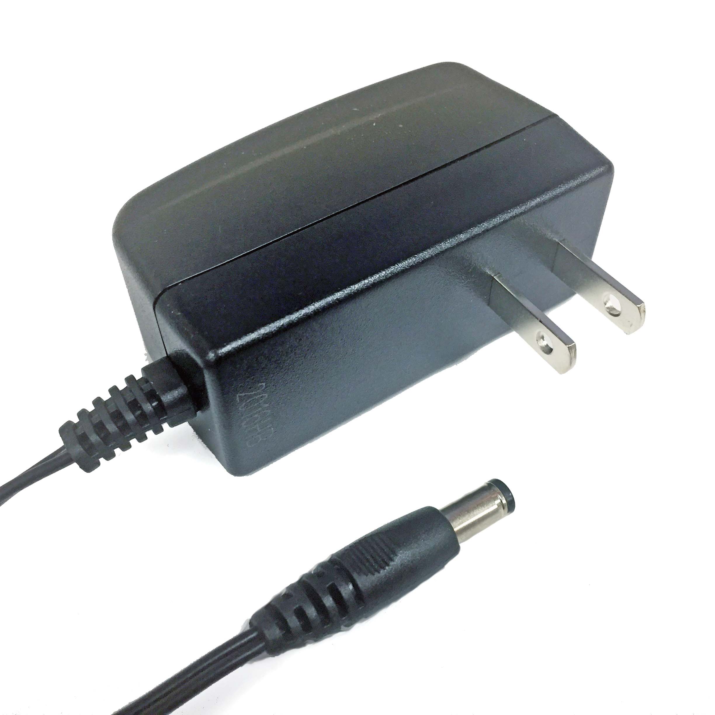
The 12 Volt Power supply is a standard power supply to convert 100-240VAC @ 0.5A (50/60Hz) to
+12VDC @ 1A used to power the BF430 RS485-to-Ethernet adapter, CR-Magnetics DC CTs and
other powered devices. May be used on 240VAC services with the appropriate adapter (not
included).
12V Power Supply
12Vdc output
120V US plug input
Isolated supply
barrel-jack connector
2-prong US style power supply with barrel jack
12 Volt Power Supply
Visit the online store page
SKU: PSU12V
Specifications
Hardware Included
Assembly/installation information


The eGauge CT Extension Kit (ESH044) allows up to four CTs to be connected to an eGauge
located within 100'/33m of the CT Extension Kit. The CT Extension Kit is designed to be installed in
a separate junction box outside the breaker panel, and requires an Ethernet run back to the
eGauge meter. With the CT Extension Kit, it's no longer necessary to extend CT leads by hand,
reducing issues with improperly spliced or extended wiring.
The eGauge CT Extension Kit is compatible with all eGauge meter models (eGauge2, EG30xx,
EG4xxx). However, firmware updates may be require to add support for certain types of CTs.
eGauge CT Extension Kit
ABS
75 x 50 x 21 (mm)
3 x 1.8 x 0.8 (in.)
2 breakway mounting tabs for 5mm fasteners
2 DIN rail 3mm coarse thread screw holes, 4mm depth on back (compatible with EG4xxx
meter mounting kit)
-30 °C to 70 °C
Humidity range: Up to 80%
47 CFR Part 15, Subpart B – Unintentional Radiators, Class B for Home or
Commercial use
eGauge CT Extension Kit
Specifications
Full specs (data-sheet PDF)

1x Sensor Hub
RJ-45 coupler
19" RJ-45 to 2-pin breakout cable
This is the main unit.
Hardware included
Assembly/installation information
Do not connect the Sensor Hub Ethernet port to an Ethernet network. It is only used to carry
signals from the 2-pin inputs on the Sensor Hub to the eGauge 2-pin ports.
The CT Extension Kit consists of three components:
1. Extension Hub (Sensor Hub)
2. Hub RJ-45 to 2-pin breakout cable (whip)
3. RJ-45 Coupler
1. Extension Hub (Sensor Hub)

The RJ-45 jack is used to connect the hub to the eGauge. The four switches A through D on the
face of the unit must be set to the right-most position. The hub does not require power.
This connects the hub to the eGauge.
The eGauge to hub connector splits the RJ-45 cable into four sensor channels. To install, connect
the two pin CT plugs to CT ports on the eGauge. Connect the RJ-45 plug to the Extension Hub
(either directly or using the coupler).
Note that the wire colors on the two pin plugs correspond to the colors on the front of the
Extension Hub. For example, the two pin plug with orange wires would be input "A" on the hub.
Do notconnect the RJ-45 plug to an Ethernet port on the eGauge or any other hardware.
Damage may result.
This can be used to extend the distance between the eGauge and the Extension Hub.
The coupler provides a convenient means to extend the wiring between the eGauge and Extension
Hub. It does not require power. The RJ-45 plug on eGauge to hub connector (whip) is connected to
one side, and a standard CAT5 cable is connected between the coupler and the Extension Hub on
the other side.
An extension of up to 100'/33m may be used. Longer runs may work, but could also lead to a loss
of accuracy. Care should be taken to ensure the extension is wired to the T568B CAT5 standard to
avoid mixing up sensor inputs. If in doubt, compare the wiring of the extension to the color key
located above the Extension Hub RJ-45 port.
2. Hub RJ-45 to 2-pin breakout cable (whip)
3. RJ-45 Coupler

The image below shows a simplified CT Extension kit wiring diagram. The Extension Hub must be
installed in a separate enclosure. Always adhere to code requirements during installation.
Multiple CT Extension Hubs can be connected to a single eGauge meter. Care should be taken to
identify the hubs correctly, in order to avoid mixing up CTs.
Diagrams

The CT Extension Hub does not require any special configuration when used with CTs. Simply
specify the CT type (manufacturer, physical diameter, amperage) and create registers as normal.
For example, assume two J&D 10mm 50A CTs on CT ports one and two. Assuming they are each
monitoring a single 120V branch circuit (eg, CT1 is monitoring lights and CT2 is monitoring
receptacles), the eGauge configuration might look like this:
Current Transformers (CTs) and Sensors
Selecting the correct CT
Software configuration Information
Related Information

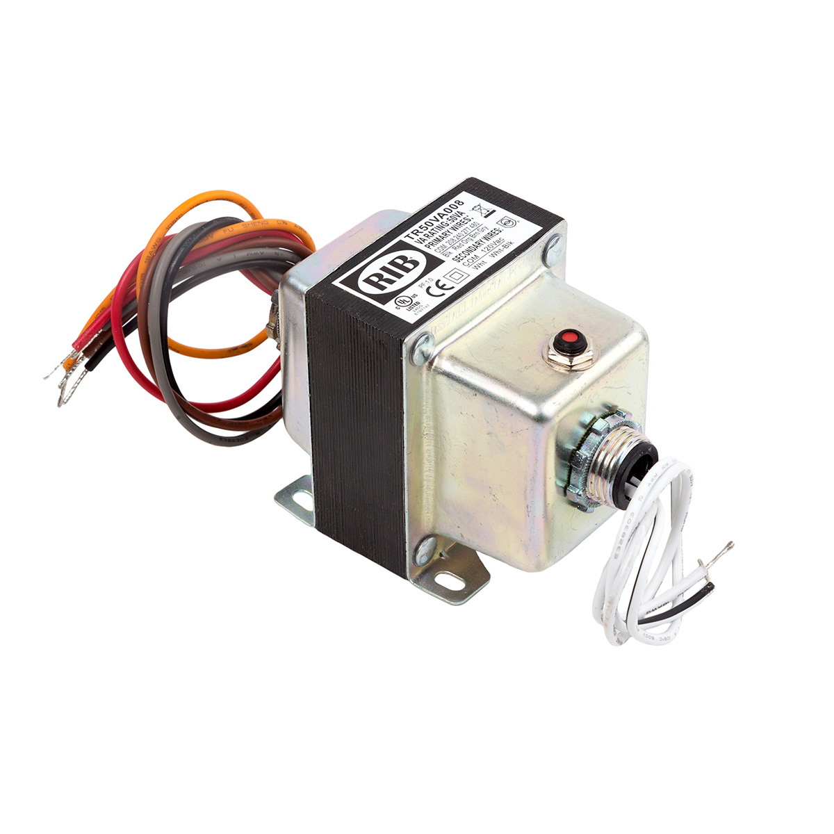
Current manufacturer information: Functional Devices model TR50VA008
Step-down transformer (480/277/240/208 to 120V)
208/240/277/480V to 120Vac, dual hub, 50VA UL Listed transformer. Used for monitoring 480V
delta services and powering 120V accessories from higher voltage systems.
VA Rating: 50
Frequency: 50/60 Hz
Mounting: Foot & Dual Threaded Hubs
Over Current Protection: Circuit Breaker
Dimensions: 3.440 x 2.510 x 3.012 (w/ .500 NPT Hubs)
Step-down transformer
Visit the online store page
Stepdown transformers are intended only to power 120V equipment off higher voltage
service. To measure 480V delta systems (no neutral), 600V delta systems (no neutral), or
347/600V Wye, please use the EV1000 High Voltage Sensors.
Transformers provided by eGauge are 50VA (50 watts limit at 1.0 power factor, lower
wattage when power factor < 1). They are intended to be used for powering a small amount
of equipment provided by eGauge. Attempting to supply loads ~50VA or higher will cause
the transformer to trip and require a manual reset.
Specifications
Full specs (data-sheet PDF)

Wire Length: 9.5 Typical w/ .5 Strip
Operating Temperature: -30 to 140° F
MTBF: 100,000 Hours @ 77° F
Construction: Split-Bobbin
Weight: 3.04 lbs.
Approvals: UL5085-2 Listed General Purpose, US / Canada, CE, RoHS
Step-down transformer
Follow instructions included with transformer, ensure correct primary and secondary wires are
used.
Spec Sheet
277V Powered Enclosure Kit
Potential Transformer Configuration
Monitoring 480V and 600V systems
EV1000 High Voltage Sensor
Hardware included
Assembly/installation information
Documents
Related Information
Table of contents
Other eGauge Systems LLC Measuring Instrument manuals

Popular Measuring Instrument manuals by other brands


ROOTECH
ROOTECH ACCURA 3700 Series user guide

Triplett
Triplett CFM400 user manual

Applied Photophysics
Applied Photophysics Chirascan CD quick start

Harbor Freight Tools
Harbor Freight Tools 91194 operating instructions

Agilent Technologies
Agilent Technologies PSA Series Getting started guide

Knick
Knick Stratos Eco 2405 Cond user manual


