Egcon SMS TYPE User manual

1
Automatic Battery Charger Manual
( MODEL : SMS TYPE )
●
●●
●
WARNING :
To prevent personal injury or equipment damage, only qualified technicians /operators
should install, operate or service this device.
●
●●
●
CAUTION :
Megger and high potential test equipment should not be used.
Incorrect use of such equipment could damage components contained in the unit.
1. APPLICATION
:
This automatic battery charger has been designed to continuously charge
a Lead-Acid Battery to start engine generator set by the switching mode
power supply (SMPS)
,
which is most essential to give emergency power to
the equipment in the event of main power failure.
2. FEATURES :
2.1. Charges batteries with constant voltage and current.
2.2. Protection against the reverse property of battery.
2.3. Current limited automatically (does not require disconnect on engine crank).
2.4. Low ripple voltage (below ±1%).
2.5. Durable for continual use at maximum capacity by wide heat radiation area.
2.6. Durable under a damp and vibrating environment by silicon coating.
2.7. Useable for 50Hz & 60Hz.
2.8. Equalizing and floating charging.
2.9. High efficiency (over 80%).
2.10. Battery discharge protection at AC input power off (Patented).
2.11. Adopted Switching Mode Control method (SMPS).
2.12. Easily field adjustable without battery connection.
3. SPECIFICATION :
3.1. Control panel mounted type.
3.2. Input voltage : 220 Vac ±10% (110Vac : optional)
3.3. Frequency : 60Hz or 50 Hz
3.4. Phase : a single phase
3.5. Output voltage : 24Vdc or 12 Vdc
3.6. Output current : 5Adc , 10Adc
3.7. Output control mode : Switching Mode by use of
F.E.T
3.8. Output control method : constant voltage and current.
3.9. Efficiency : over 80%
3.10. Setting voltage for float charging 24V Battery - 26.4Vdc
12V Battery - 13.2Vdc
3.11. Setting voltage for equalize charging 24V Battery - 28.8Vdc
12V Battery - 14.4Vdc
3.12. Charging current adjustable range : less ±20% of nominal current value
3.13. Durable time at over load : 2 hours at 120% of nominal current value
3.14. Voltage adjustable range for float charging and equalize changing :
2
METHOD 24V battery system 12V battery system
Float charging 26.4V dc ±5% (=24 ~ 28Vdc) 13.2Vdc ±5% (=12 ~ 14Vdc)
Equalize charging 28.8V dc ±5% (=26 ~ 30Vdc) 14.4Vdc ±5% (=13 ~ 15Vdc)
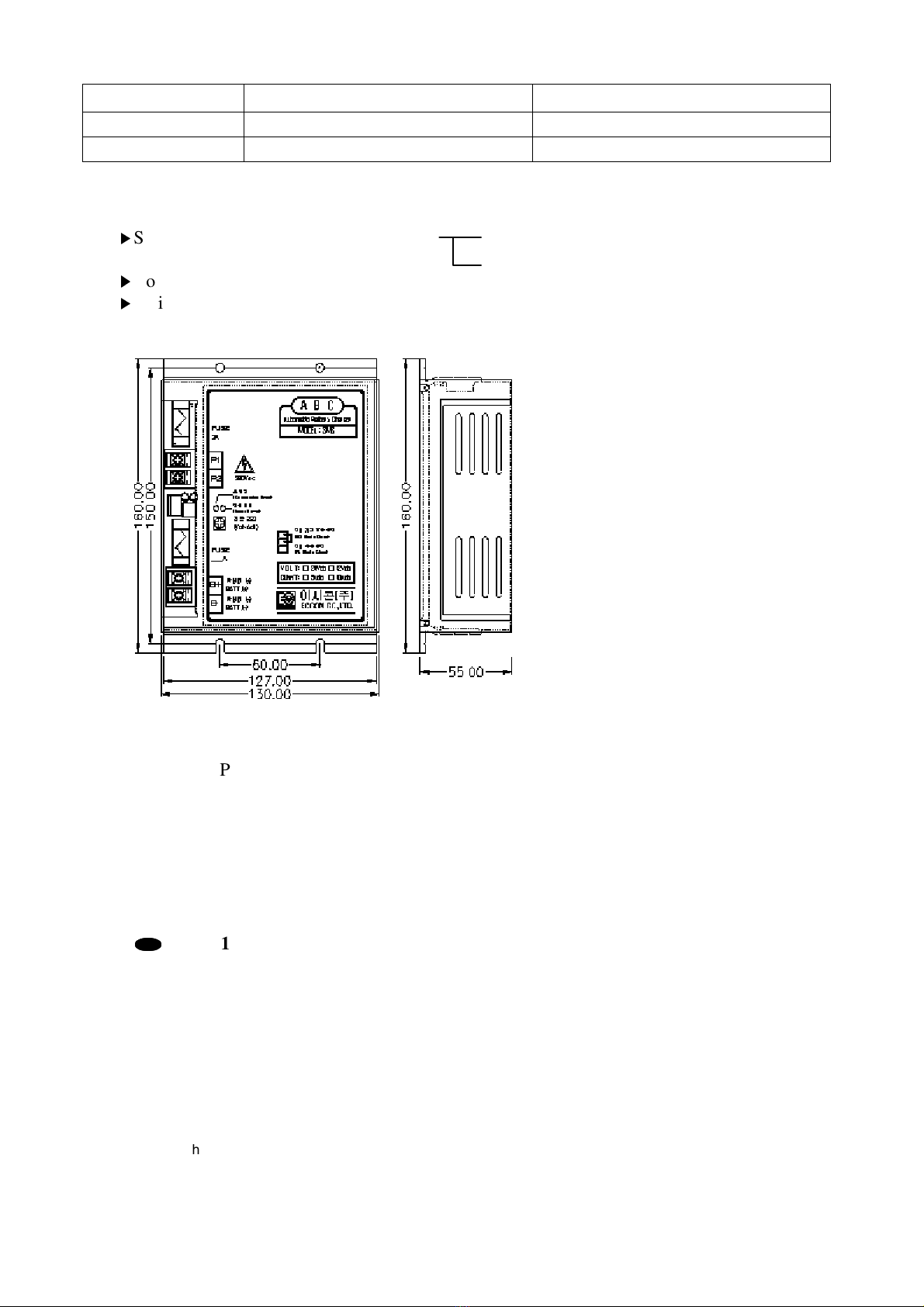
4. STRUCTURE
▶
Size (W * D * H) : 130 * 55 * 160(mm) 12Vdc-5A,10A Charger.
24Vdc-5A,10A Charger.
▶
Color : Bottom- dark gray , Cover- ivory
▶
Weight : about 1.2kg
APPERANCE
5. CONDITION FOR USE :
5.1. Ambient Temperature : -10℃
∼+40
℃
(storage temperature : -25 ~ 60 ℃)
5.2. Relative Humidity : 85 %
●
●●
●
NOTE 1
Be sure area around battery is well ventilated and away from a damp, vibrating
environment and contaminated substance.
6. INDICATIORS AND ADJUSTER :
6.1. Input power [yellow] : indicates when AC input power turns on.
6.2. Connection error [red] : indicates B+ and B- line reverse connection to the battery.
6.3.
Charging select
Connector
floating charge: Charge indicator lamp next to the connector link
Equal Charge: Charge indicator lamp next to remove the connector
7. INPUT & OUTPUT TERMINALS :

3
7.1. P1,P2 ; AC power input terminals to 220Vac power
7.2. B+,B- ; DC power output terminals, B+ should be connected to the positive terminal of the
battery and B- to the negative.
8. INSTALLATION AND CONNECTION
8.1. Installation
The charger shall be installected well ventilated away from a damp, vibrating, environment and
without substance to obstruct maintenance and access.
8.2. Connect the specified AC input power with P1, P2 terminal of battery charger.
8.3.
Connect the positive line of battery to B+ and the negative line to B-, respectively.
8.4. Check if connection error lamp indicates in above8.3, and correct the properties of the lines
(B+, B-) to the battery.
WIRING CONNECTION
4
9. TEST AND OPERATION
9.1. Turn on AC input breaker, then input power indicator lights.
9.2. If the connection error indicator lights, check the properties of battery.
9.3. Charging method selection
▶Float charging
This charging is normal operation mode to charge the battery for starting the engine genset,
which stands by main power cut off. When all connection have been completed as per above
wiring connection drawing, then make two breakers (AC input, DC output) “ON”, charger
starts charging action at float charging.
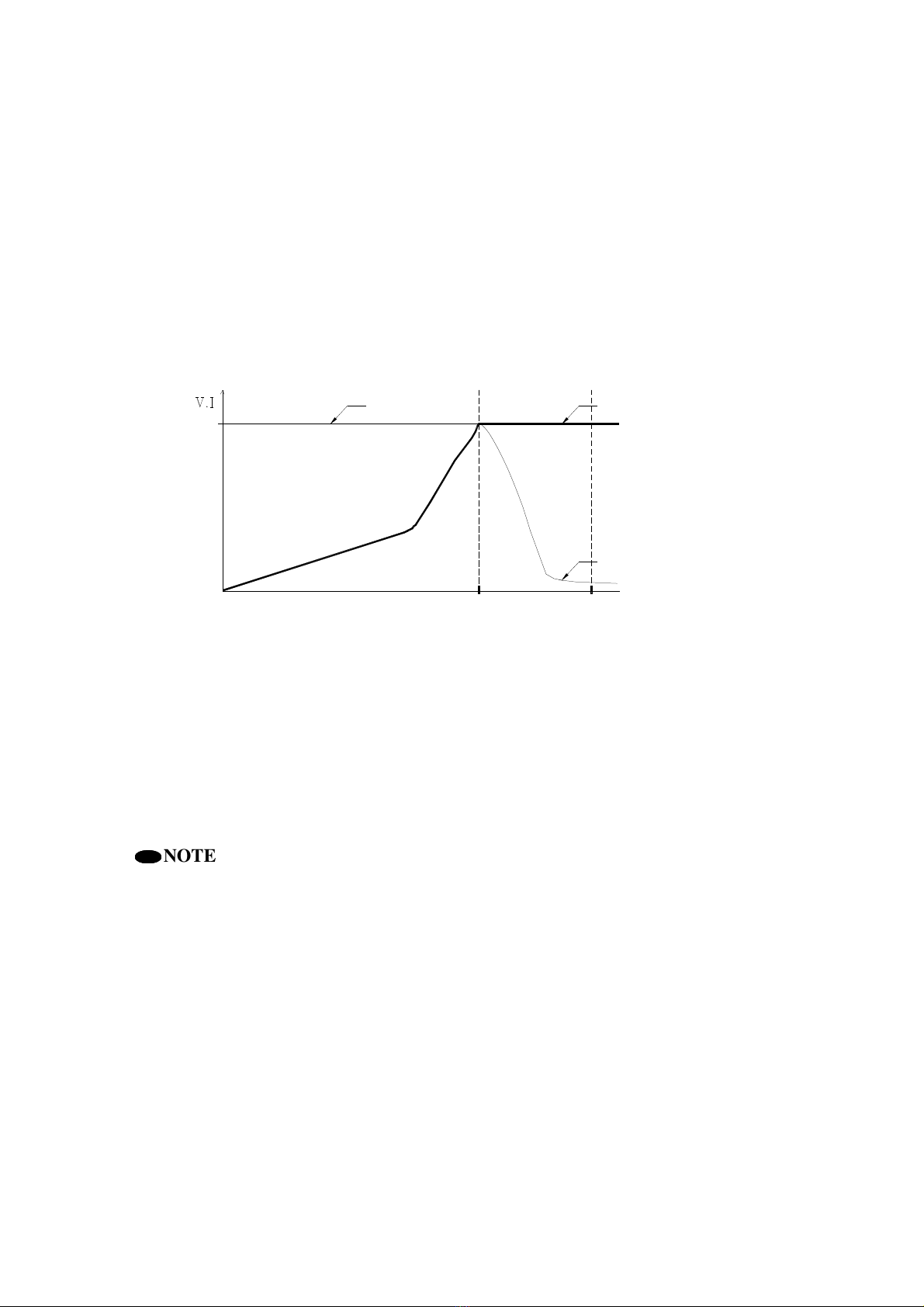
full charging point
start point
charge
0float charging point
charging current float charging voltage
charging current
FLOAT CHARGING CURVE
As the battery is installed from storage condition and the charger start charging battery charger
operates along with above float charging curve. In other words, when two breakers turn on,
the charger supply the nominal current to the battery at low voltage until it reaches full charge
point, from this point the current decrease slowly to keep on a little current at constant voltage
(= float charging voltage),
●
●●
●
NOTE 2
Generally, on float charging mode not to need a rush current like engine starting, the
battery charger must keep output voltage to be a constant float charging voltage at the
full charged condition of the battery and output current below 1.5 ~ 2Adc, which is the
current to supply the consumption quantity for the electrical loads connected to the
battery. But when engine starting occurs with the battery under-charged below float
charging voltage, the charger will supply all of theses current to the load and it may
cause battery damage.
▶Equalize charging
The purpose of the periodic equalize charging is to ensure that all of the battery cell are
at full charge. but, equalizing voltage charge should be done until the equalize charging
time expires one time every 3 months.
This charging starts by pushing equalize charging start push button [red color], equalize
charging voltage is set at the factory before it ex-work.

5
9.4. Adjusting floating and equalizing voltage are set by VR2 on the PCB inside of battery charger.
9.5. Limit current adjustment.
Turing potentiometer VR1 on the PCB of battery charger cause to change DC output current
limit up to ±20% of nominal current. This current limit values is set at the factory prior to
ex-work.
●
●●
●
NOTE 3
When charging mode select switch is in equalize position, be careful not to be over-
charged into the battery, to avoid battery’s overcharge, Equalize charging time is
recommended below 6hrs
.
10. TROUBLE SHOOTING
SECTION SYMPTOMS PROBABLE CAUSE ACTION
No output
No DC output
and AC failure
lamp lights.
1.AC input power is cut off.
2.AC input breaker open
3.DC output breaker open
1.Check the AC input lines and
fuse inside of the charger.
2.Turn on the breaker.
3.Turn on the breaker.
Fault
Connection Error
Lamp lights.
Two lines(B+,B-) to the
battery has wrong
connection.
Check the property of the battery
and correct the lines.
Fused to exchange
Battery’s
Problem
1.The charger
doesn’t work.
2.Charger’s input
breaker off
immediately.
1-1.Battery’s remaining
voltage is below 7Vdc.
1-2.The poor battery charger
2.Leads(wires) short circuit.
1-2.Replace with new one.
2.Open the cover and check leads
inside of the charger.
Table of contents
Popular Batteries Charger manuals by other brands


Blueshape
Blueshape CGTR2P operating instructions

Vector
Vector VEC1088 A Owner's manual & warranty information

KRESS
KRESS KAC21 Safety and operating manual

Lab-T
Lab-T GF520 user manual

Tronic
Tronic TLG 500 B1 operating instructions

Telex Communications
Telex Communications BC-800NM4 Features & specifications