USER MANUAL
GARANTI INFO/WARRANTY INFORMATION
EU COUNTRIES (EXCEPT SWEDEN)
Sverige/Sweden
Garantivillkor enl ALEM 09.
OBS! Fullständigt ifylld garantiblankett krävs
1. The product benefits from warranty, Technical support and
free service for a period of 24month or according to local
agreement from the date of installation / commissioning,
Thus undergoing repair or (if not possible) free replacement of
any parts that have manufacturing defects. The deadline for
resolving the non-compliance is 60 days.
2. The product must be installed by a certified installer /
contractor.
3. Proper installation, storage and operation conditions must be
obtained.
4. Warranties apply only to products installed in their original
installation location.
5. Installation, use, care, and maintenance must be normal and
in accordance with instructions.
6. Warranty requires a dated, fully filled in Warranty form by
an certified installer/contractor. If the original installation date
cannot be verified, then the warranty period begins ninety
(90) days from the date of product manufacture (as indicated
by the model and serial number).
7. Warranty does not cover damage occured by incorrect use
of equipment, use of any nonoriginal spareparts, lack of
maintenence or faults caused by disassembly of the product
or unauthorized persons intervention.
8. Warranty does not cover aesthetic deficiencies caused by
negligent manipulation or accidents (breaks or damage to the
carcass).
9. Warranty does not cover damage caused by external
overvoltage from either grid or car/charging object.
10. Warranty does not cover damage caused by force major like
for example but not limited to: floods, winds, fires, lightning,
accidents, sabotage, military conflicts, terrorism, vulcanos,
earthquakes or corrosive environments.
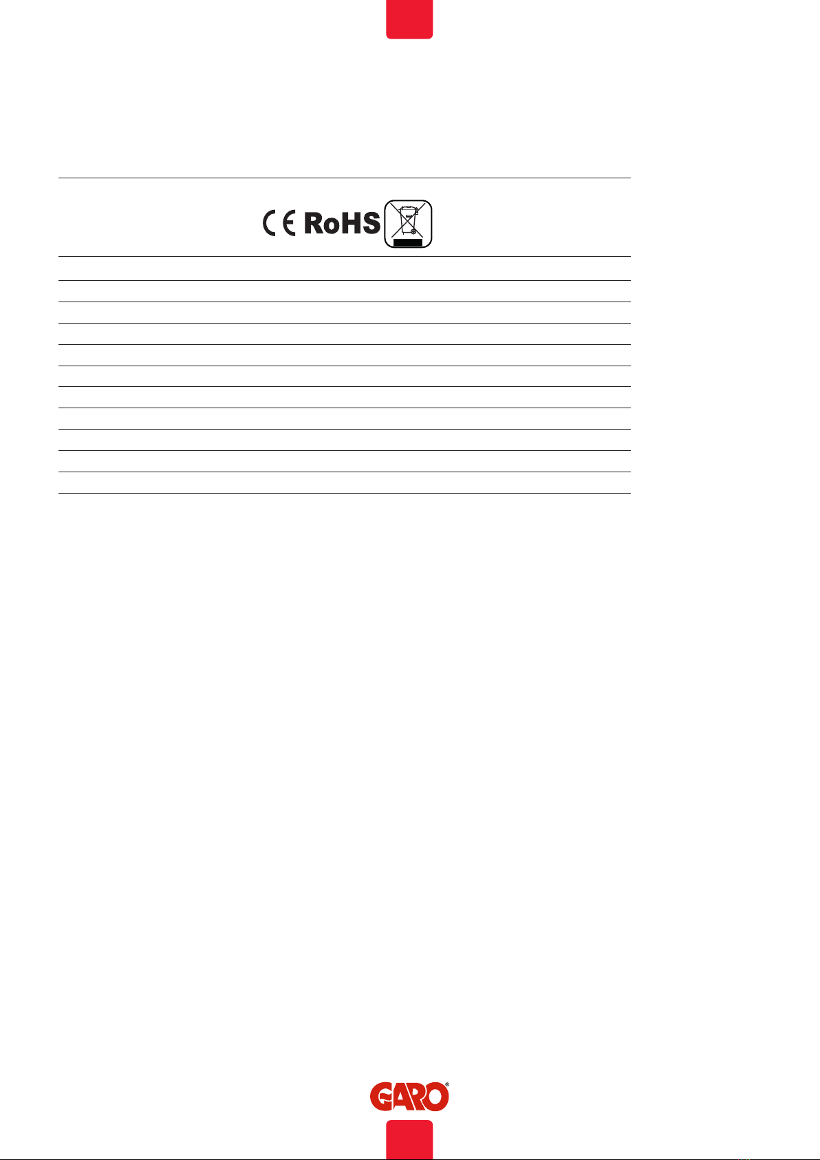
Technical specifications
Product type: All GTB models
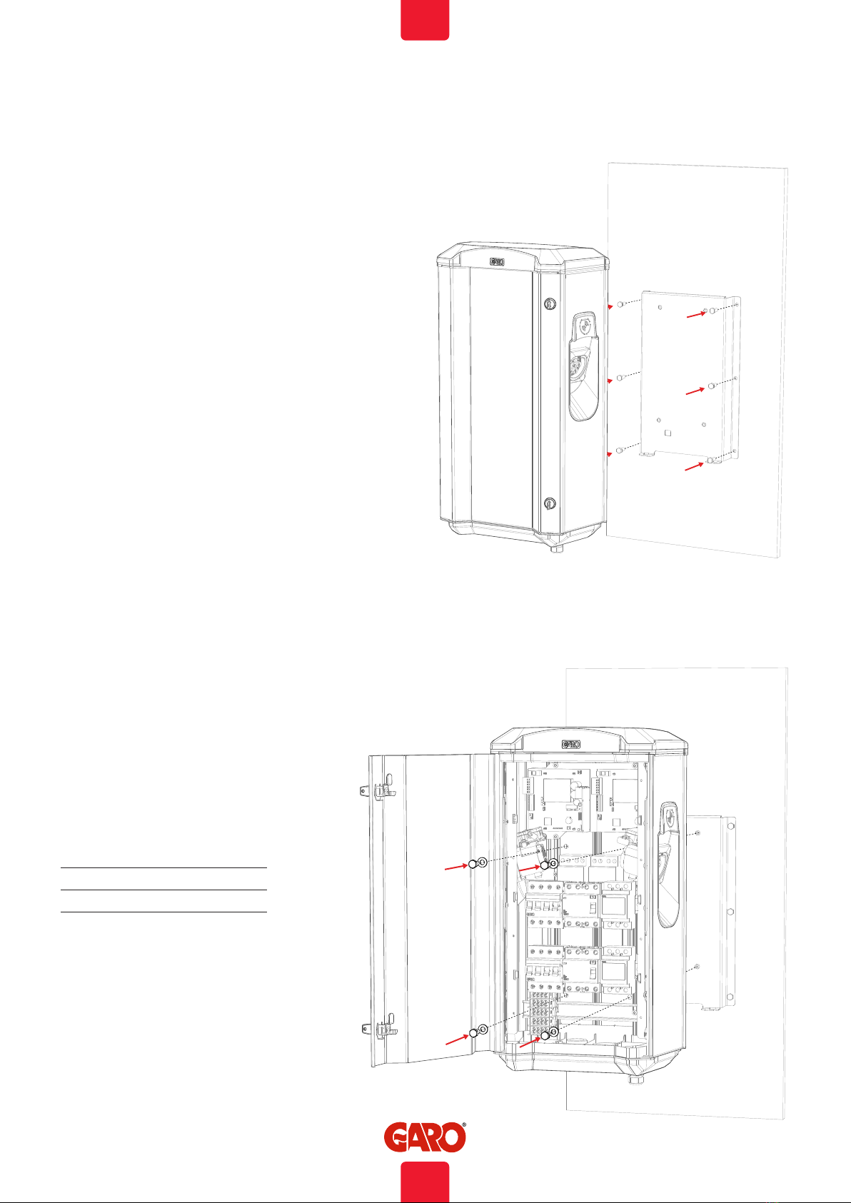
Standards/directives: IEC 61851-1 and IEC TS 61439-7
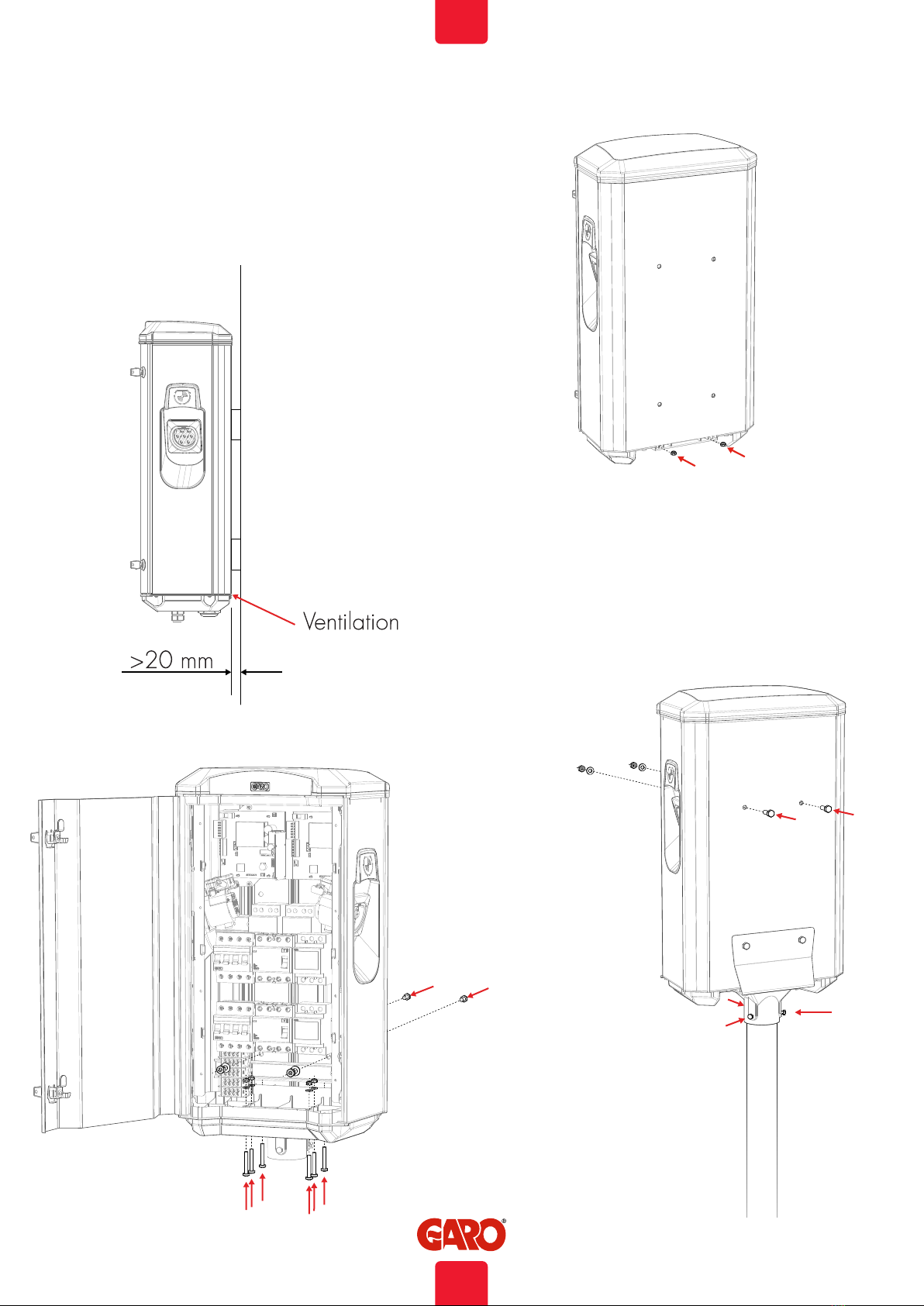
Installation: Wall/pole mounted
Voltage rating: 230V/400V 50Hz
Installation systems: TT-, TN- and IT*-systems
Charging Type: Mode 3
Charging method: AC charging
Protection class: IP44
Mechanical impact resistance: IK10
Temperature range: -25C – +40C (without direct sunlight)
Recommended installation height: 0.5–1.5 metres above ground
Weight: 14-18 kg
Standard cable length (fixed cable
versions):
4m
* 1-phase Twinbox
10
EN