EGS Appleton CPP-2023 User guide

330107-1
INSTALLATION AND
APPLICATIONS INSTRUCTION
Instruction Sheet for Appleton’s 20 Amp “CPP” Plug
Applications:
• Locations where receptacles are used with stationary
or portable electrically operated devices such as
lighting systems, conveyors, heaters, motor-generator
sets, air conditioner compressors and pumps.
• Locations where damp or corrosive conditions are
encountered.
• Class I –classified areas such as petrochemical
plants, petroleum refineries, paint and chemical plants
or any location where ignitable vapors or gases are
present.
• Class II –locations such as process industries where
there are dust hazards from handling such products
as flour, grain and starch or any location where
ignitable amounts of dust are present or amounts
which would otherwise effect performances.
Operational Data:
• Lift receptacle door and insert plug all the way into the
receptacle.
• Turn plug clockwise limit (37˚). This closes internal
contacts and completes circuit.
• Release plug.
• To remove plug, apply inward pressure on plug and
turn to counter-clockwise limit (37˚). Pull plug straight
out.
Features:
A. Heavy duty cable grip exceeds UL Standard 1010,
150 lb. pull-out test for classified locations.
B. Twisting plug locks it in place, cannot be accidentally
pulled out.
C. Special neoprene plug bushing accommodates
flexible cord ranging from .536 to .639 inch diameter.
D. Longer plug housing for better gripping and easier
plug insertion and withdrawal.
CABLE DIA. CATALOG NUMBER
AMPS DIAGRAM WIRE/POLE (INCHES) 125-250V A.C.
20 2W, 3P .536 - .639 CPP-2023
Class I, Groups B,C,D
Class II, Groups F,G
Class III
The CPP-2023 plug is designed for use with the following receptacles in Class I, Groups B,C,D; Class II, Groups
F, G; and Class II, Division 1 and 2 hazardous locations:
CPSA-2350 CPSA-2375 CPSC-2350 CPSC-2375 CPSE-2350 CPSE-2375
CPSL-2350 CPSL-2375 CPST-2350 CPST-2375 CPSX-2350 CPSX-2375
CPE1-2350 CPE1-2375 CPE1-23100 CPC1-2350 CPC1-2375 CPC1-23100
EFD150-NL EFD175-NL EFD110-NL EFDC150-NL EFDC175-NL EFDC110-NL
The CPP-2023 plug is designed for use with the following receptacles in Class I, Groups C,D; Class II, Groups
F, G; and Class II, Division 1 and 2 hazardous locations:
CPE2-2350 CPE2-2375 CPE2-23100 CPC2-2350 CPC2-2375 CPC2-23100
EFD250-NL EFD275-NL EFD210-NL EFDC250-NL EFDC275-NL EFDC210-NL
CPR-23
EGS Electrical Group • 7770 North Frontage Road • Skokie, IL 60077 Rev. A 06/25/02 Page 1

Instruction Sheet for Appleton’s 20 Amp “CPP” Plug
Page 2 330107-1 Rev. A 06/25/02 EGS Electrical Group • 7770 North Frontage Road • Skokie, IL 60077
Instructions:
1. To disassemble device as shown, remove clinch ring
(1) from plug housing (2) interior.
2. Remove terminal block assembly (5) and insulator
clamp assembly (3) from plug housing (2).
3. Strip the cable jacket and individual conductors per
Table A.
Caution:
Care must be taken not to cut into the individual
conductor insulation when removing the outer cable
jacket and to not damage the conductors when
removing individual wire insulation.
Failure to do so will seriously degrade the electrical
properties of the cable and may produce
overheating/electrical hazard leading to
electrocution.
4. Slide plug housing (2) over cord (4).
• The self sealing neoprene bushing will adjust to cord
diameter.
5. Loosen four clamp screws (7) from insulator clamp
assembly (3).
Note:
The CPP Plug should be wired with three conductor
rubber covered #12 AWG through #14 AWG Type
SO Cords with copper conductors ONLY.
6. Slide insulator clamp assembly (3) over cord (4).
7. Separate front terminal block (9) from rear terminal
block (5). Fasten individual conductor wires to terminal
block assembly as follows:
For 125V: Green wire to grounding plug terminal “G”
(11).
White wire to lug terminal “W”.
Black wire to remaining lug terminal.
For 250V: Green wire to grounding plug terminal “G”
(11).
Other 2 wires to remaining 2 lug terminals.
Tighten terminal screw to a torque of 9 in.-lb.
Minimum/11 in.-lb. Maximum.
8. Slide insulator clamp (3) over cord (4) until it is seated
against the terminal block assembly.
9. Place the cord clamp (8) as shown in Table B
according to cable diameter and tighten the four
clamp screws (7) to a torque of 10 in. -lb. Minimum/11
in.-lb. Maximum.
Caution:
DO NOT attempt to over-tighten the screws or
bottom the clamp.
10. Slide plug housing (2) over insulator clamp
assembly (3) and terminal block assembly. Rotate
housing to find correct orientation
11. Insert clinch ring into plug housing interior.
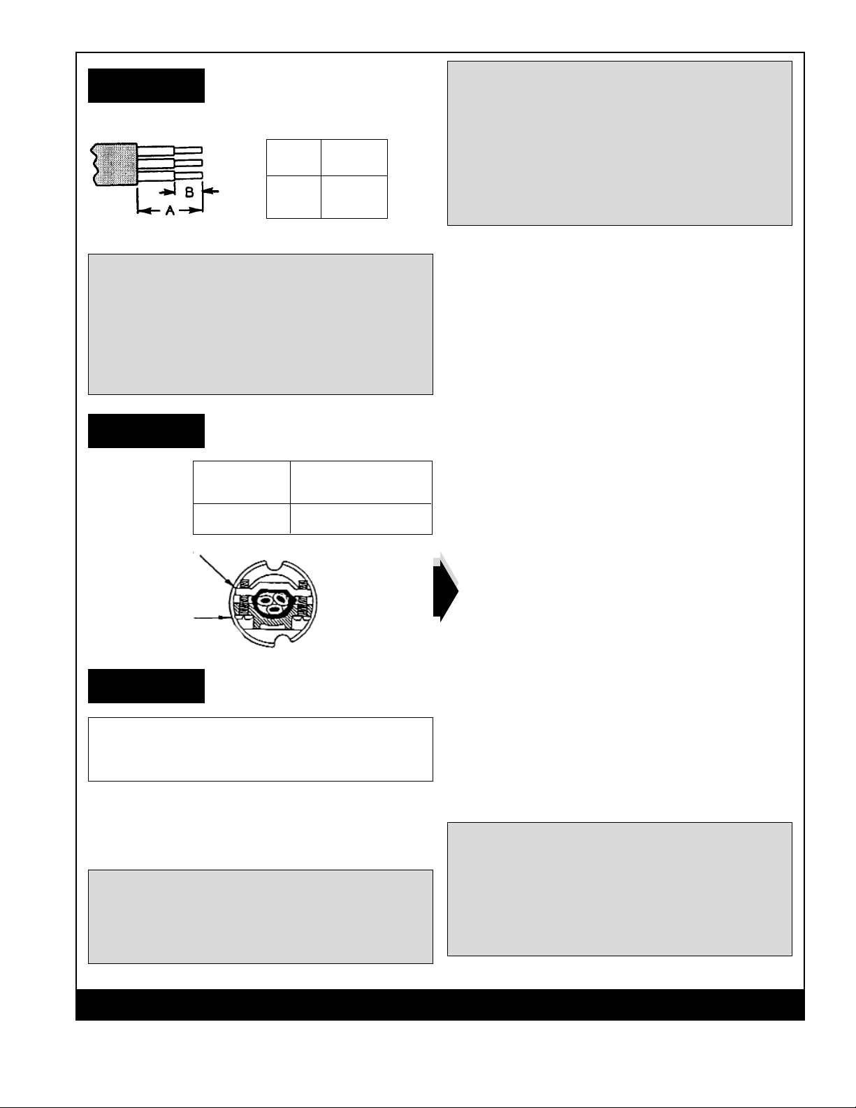
Table A
EGS Electrical Group • 7770 North Frontage Road • Skokie, IL 60077 330107-1 Rev. A 06/25/02 Page 3
Terminal Wire Stripping Guide
A1
1/2
B5/16
Warning:
Use cable with diameters within the specified range
given in Table B.
Failure to do so may result in over stressed wore
terminations which could cause the conductors to
pull out of the contacts and cause serious/fatal
injuries due to electrocution.
CORD DIA. CORD CLAMP
INCHES CONFIGURATION
.539 - .639 See Figure 1
Caution:
Plug and cord connections are rated for use with
Type SO cord with copper conductors ONLY.
Maintenance:
Electrical and mechanical inspection of all components
must be performed regularly. It is recommended that
inspection be performed a minimum of once a year.
Warning:
• Electrical power must be turned “OFF” before and
during installation and maintenance.
• Failure to do so may result in serious or fatal
injuries due to electrocution.
Warning:
If any parts of the plug, receptacle or cable
connector appear to be missing, broken or show
signs of damage:
DISCONTINUE USE IMMEDIATELY
This condition could cause serious/fatal personal
due to electrocution and or equipment damage.
Repair with proper replacement part(s) before
continuing use.
1. Inspect all contact wire terminals for tightness.
• Discoloration due to excessive heat is an indicator of
possible problems and should be thoroughly
investigated and repaired if necessary.
2. Check grounding and bonding for correct installation
and secure connection. (Retorque).
3. Check gaskets for deterioration and replace if
necessary.
4. Clean exterior surfaces making sure nameplates
remain legible.
5. Inspect cable grip tightness to ensure proper
cord/cable gripping.
6. Torque all screws as described in instructions before
using device.
7. Inspect all parts and replace those which are broken
or excessively worn.
8. Check contacts for signs of excessive arcing or
burning and replace if necessary.
In addition to these required maintenance
procedures, we recommend an Electrical Preventive
Maintenance program as described in the Nation
Fire Protection association Bulletin NFPA No. 70B.
Electrical Testing:
Do not connect to power until conducting the following
electrical tests:
• Test continuity of wiring to verify correct phasing and
grounding connections.
• Measure insulation resistance to be sure system
does not have any short circuits or unwanted grounds.
Electrical Ratings:
125-250V A.C., 20A at 2 H.P.; 28V D.C.
Warning:
• Do not modify these devices in any way.
• Replace any missing or broken parts with proper
replacement parts from Appleton Electric, LLC.
• Modifications of these devices or substitution of
parts with non-standard parts may result in
serious/fatal personal injury from electrocution.
Table B
CORD
CLAMP
INSULATOR
CLAMP
Figure 1
RETAIN THIS INSTRUCTION SHEET FOR FUTURE REFERENCE
Page 2 330107-1 Rev. A 06/25/02 EGS Electrical Group • 7770 North Frontage Road • Skokie, IL 60077
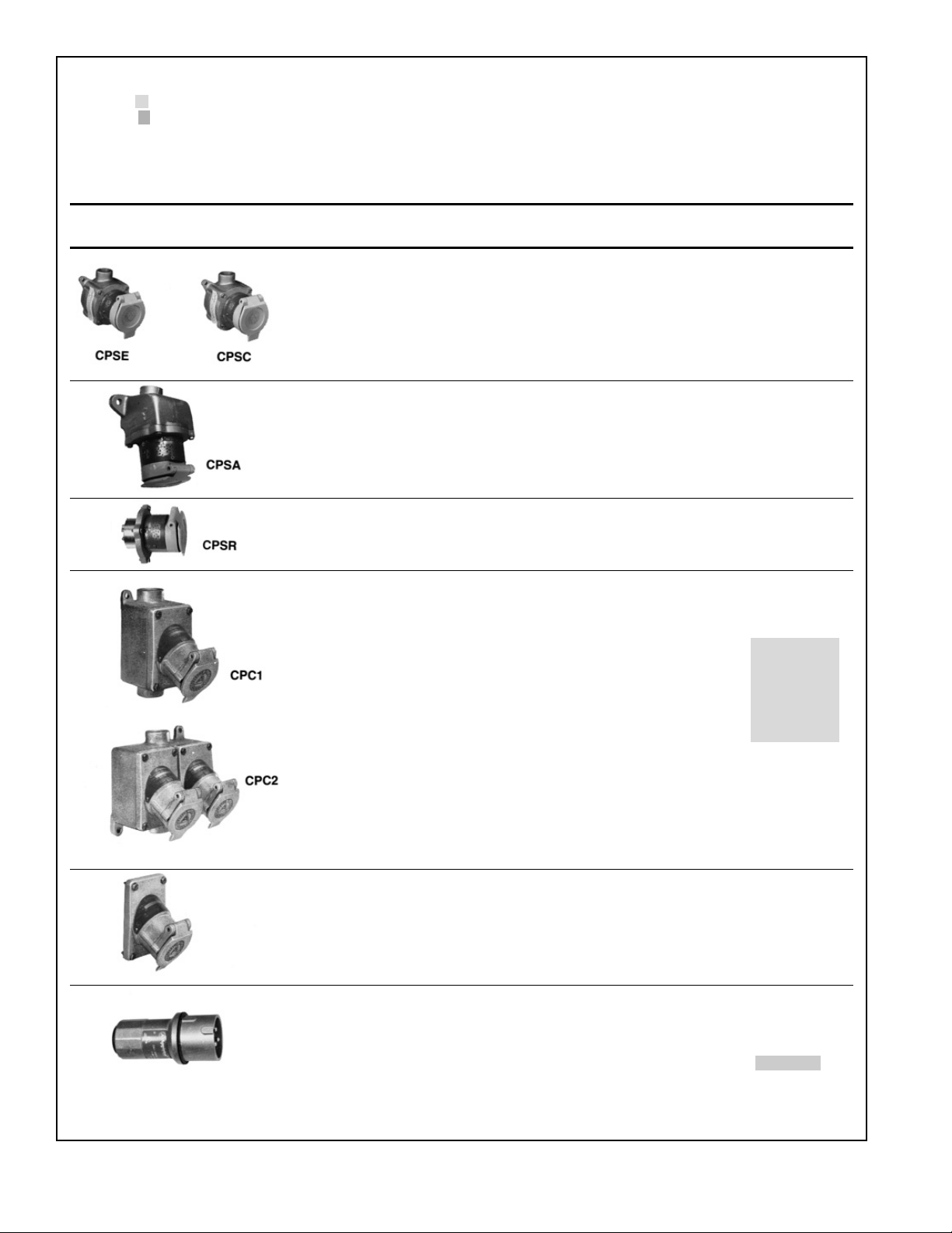
20 Amp CPS Factory Sealed
Receptacles: Explosionproof
Dead-Front Safety Construction—Grounding thru Extra Pole and Shell.
Hub Size, Catalog
Type Wire/Pole Inches Number
CPS Receptacles
120-240V A.C., 20A at 1 H.P.; 20A at 24V D.C.
Dead-End 2W,3P 1/2 CPSE-2350
3/4 CPSE-2375
Feed-Thru 2W,3P 1/2 CPSC-2350
3/4 CPSC-2375
CPS Receptacle 15° Angle Type
120-240V A.C., 20A at 1 H.P.; 20A at 24V D.C.
Dead-End 2W,3P 1/2 CPSA-2350
3/4 CPSA-2375
CPS Receptacle Only (Replacement)
CPSR 2W,3P CPSR-23
CPS Receptacles with EFD Mounting Boxes
120-240V A.C., 20A at 1 H.P.; 20A at 24V D.C.
Single Gang
Dead-End 2W,3P 1/2 CPE1-2350
3/4 CPE1-2375
1CPE1-23100
Feed-Thru 2W,3P 1/2 CPC1-2350
3/4 CPC1-2375
1CPC1-23100
Two Gang
Dead-End 2W,3P 1/2 CPE2-2350
3/4 CPE2-2375
1CPE2-23100
Feed-Thru 2W,3P 1/2 CPC2-2350
3/4 CPC2-2375
1 CPC2-23100
CPS Receptacle Only (Replacement)
CPR 2W,3P CPR-23
CPP Plugs for use with Receptacles Above
Solder Well Wire Terminals
Cable Dia.,
Inches
Plug amperes match 2W,3P .536 to .639 CPP-2023
receptacle ratings
Class I, Div. 1 and 2
Groups B,C,D
NEMA 7BCD
Other EGS Lighting Equipment manuals

Popular Lighting Equipment manuals by other brands


Qazqa
Qazqa Suplux SL 3 Black 103062 instruction manual

Commercial Electric
Commercial Electric 54568141 Use and care guide

CREE LIGHTING
CREE LIGHTING 304 Series installation instructions

Goobay
Goobay 49867 user manual

ECOMAN ITALIA
ECOMAN ITALIA LED T8 instruction manual

Alkalite
Alkalite Krypton KT-81 user manual


