EGS Appleton Code-Master Series User manual
Description
The Code-Master™ light is an inrush current
limited strobe light that is UL Listed as a sig-
naling appliance for the hearing impaired and
is intended for indoor use in UL Listed com-
patible fire alarm systems and other applica-
tions requiring electrical supervision of signal-
ing circuit field wiring. The strobe flashes a 360-
degree beam of light approximately 65 times per
minute. The strobe is UL Listed for use in Class
I, Division 1, Group C and D; Class I, Division 2,
Group A, B, C and D; Class II, Division 1, Group
E, F, and G; Class II, Division 2, Group F and G;
and Class III Division 1 and 2 hazardous loca-
tions with Operating Temperature Codes per
the following chart.
Temperature Codes
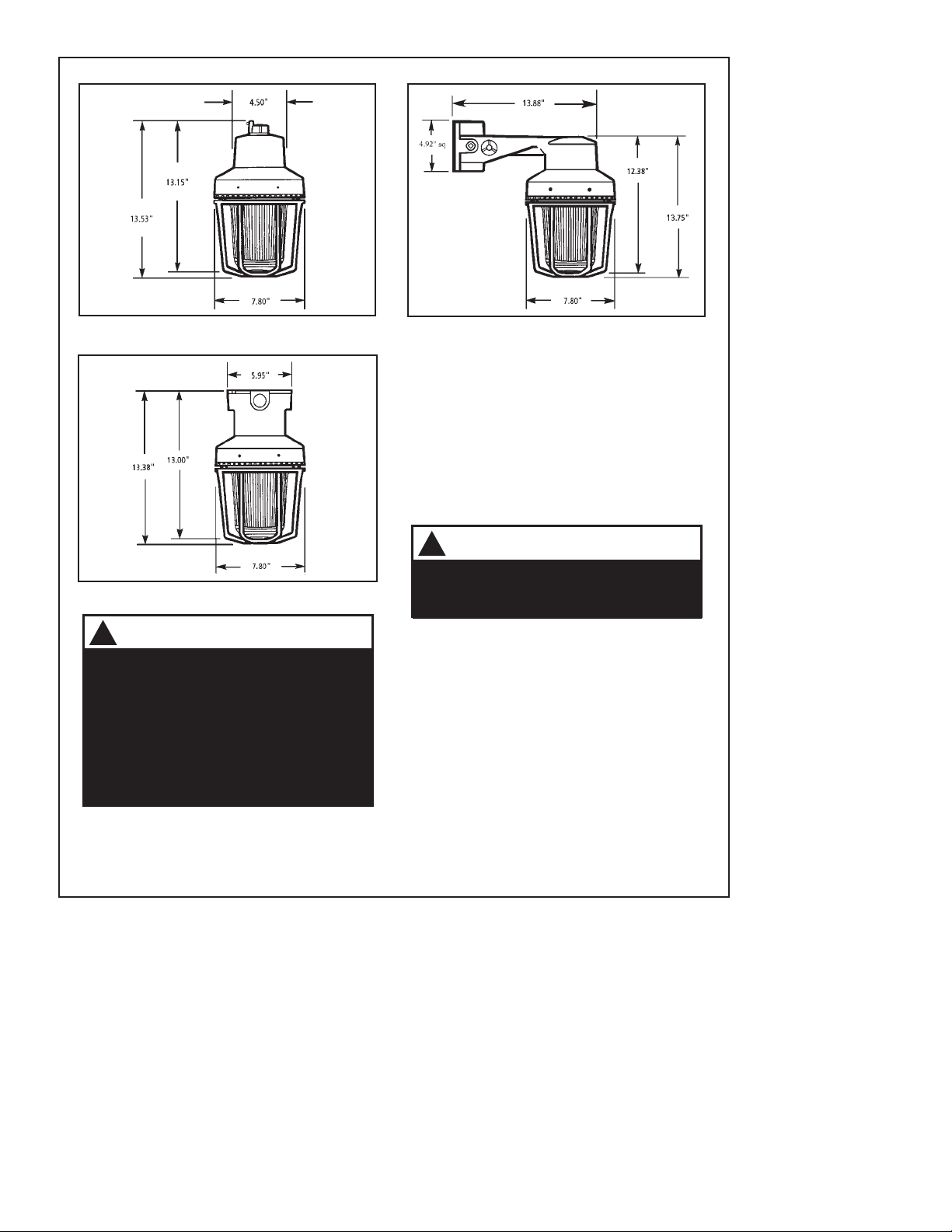
1. Mount using the following applicable method.
a. Pendant Mounting (Figures 1 and 4): Install
explosion-proof hanger box (not supplied).
Secure 3/4” (19 mm) NPT threaded conduit
(not supplied) to the box. Install the mounting
assembly, catalog number CAP75, on the
conduit. Proceed to step 2.
b. Ceiling Mounting (Figures 2 and 4): Mount
the ceiling box, catalog number CAC75, using
appropriate hardware (not supplied) suitable
for the mounting surface. Proceed to step 2.
c. Bracket Mounting (Figures 3 and 4): Install
the mounting bracket, catalog number CALB75.
using appropriate hardware (not supplied) for the
mounting surface. Pull the field wiring through
the mounting bracket. Proceed to step 2.
2. Extend the required power source wiring
down through the mounting assembly. See Table
4 for required supply wire temperature ratings.
3. Refer to Figure 4. Loosen the (2) screws
holding the circuit block in place. Rotate and
remove the circuit block.
4. A ground screw is provided in the wiring
compartment for attachment of field earth
ground wire.
5. Connect the two red positive (+) and two black
negative (-) wire leads to the supervised circuit
in accordance with Figure 4.
6. Install the fixture on the mounting assembly.
These devices are also UL 1971 Listed for
visual signaling use for the hearing impaired
with a 75 cd light output per Table 3.
Installation
EGS Electrical Group • www.appletonelec.com Rev. B 650398-001 03/29/05 Page 1
Install this unit in accordance with the applicable
requirements in the latest edition of the National
Electrical Code.
NOTE: This unit must be mounted vertically
with the globe assembly vertically facing down
in Hearing Impaired Applications.
650398-001
Installation Instructions for Code-Master™ Strob e Lights for Fire
Alarm Hearing Impaired Use In Hazardous Locations
7. Apply power to the unit and ensure proper
function.
Ambient Class I, Div. 2 Class I, Div. 1 Class II, Div. 1
Temp. Groups A, B, C & D Groups C & D Class III, Div. 1 & 2
40ºC 260ºC (T2B) 85ºC (T6) 120ºC (T4A)
55ºC 260ºC (T2B) 85ºC (T6) 120ºC ( T4A)
65ºC 280ºC (T2A) 85ºC (T6) 135ºC (T4)
WARNING
To reduce the risk of ignition of hazardous
atmospheres and shock, do not apply power
to the unit until installation has been complet-
ed and unit is tightly assembled and secured.
!
WARNING
To reduce the risk of ignition of hazardous
atmospheres and shock, keep assembly
tightly closed when circuits are energized.
!
Maintenance
1. Loosen the (3) guard screws and remove the
guard.
2. Loosen the globe and ring assembly set
screw. Insert a suitable tool into the notches
in the globe and ring assembly and loosen the
assembly by prying in a counterclockwise direc-
tion. Remove the ring and globe assembly.
Figure 2. Detail of Ceiling Mounting.
Page 2 Rev. B 650398-001 03/29/05 EGS EGS Electrical Group • www.appletonelec.com
Figure 3. Detail of Bracket Mounting.
Figure 1. Detail of Pendant mounting.
For strobe tube replacement, disconnect from
the supply circuit and allow five minutes for
stored energy to dissipate before starting work
or disassembly.
3. Refer to Table 2 for the correct replacement
catalog number and replace the necessary
part.
4. To replace, simply screw the unit on until it
seats firmly onto its gasket. Tighten the unit
another 1/8 to 1/4 turn. Tighten the setscrew.
5. Reinstall the guard, where applicable, and
secure using the three supplied screws.
6. After the unit is assembled, apply power and
make sure the unit functions properly.
WARNING
When replacing the strobe tube, do not handle
the tube. Hold the strobe tube only by its base
to prevent damage to the tube.
!
WARNING
To reduce the risk of ignition of hazardous
atmospheres and shock, keep assembly
tightly closed when circuits are energized.
To reduce the risk of ignition of hazardous
atmospheres and shock, disconnect from the
supply and circuit and allow five (5) minutes
for stored energy to dissipate before disas-
sembling the unit.
!

Table 1. Code-Master™ Strobe Light Specifications
Table 3.
Light output dispersion when mounted
with the assembly vertically facing down.
Percent
Degrees* of 75 cd Rating
0, Pointing Down 100
5 - 25 90
30 - 45 75
50 55
55 45
60 40
65 35
70 35
75 30
80 30
85 25
90 25
*Tolerance of ±degree is permitted.
Operating Current* Park Current*
Mounting (Continuous RMS, (outgoing Surge* conduit Flash Rated Light
Cat. No. Method Voltage after Init. surge) after init. surge) (Initial) Size Rated Output
CSST2030PDCCL Pendant 20V DC 1.08A 3A 10A for 0.7 ms 3/4Ó 360º beam 75cd
and CAP75 Figure 1 24V DC 0.95A 2.8A 12A for 0.7 ms NPT of light at per
CSST2030PDCCL Ceiling 30V DC 0.83A 2.6A 15A for 0.7 ms -65 fpm Table 3
and CAC75 Figure 2
CSST2030PDCCL Bracket
and CALB75 Figure 3
*Use the operating current to establish the wire gauge and standby power requirements. Consult the control unit
manufacturer to determine surge and peak current effects and maximum number of strobes on the system.
Table 2.
Code-Master™ Strobe Light
Replacement Parts
Mounting Replacement
Cat. No. Method Strobe
CSST2030PDCCL Pendant Cat. No.
and CAP75 Figure 1 S865
CSST2030PDCCL Ceiling
and CAC75 Figure 2
CSST2030PDCCL Bracket
and CALB5 Figure 3
Table 4
Supply Wire Temperature Markings
Ambient Supply Wire
Temperature Temperature Marking
40ºC 75ºC
55ºC 85ºC
65ºC 110ºC
EGS Electrical Group • www.appletonelec.com Rev. B 650398-001 03/29/05 Page 3

Figure 4. Wiring Diagram
FROM
POWER SOURCE
OR PREVIOUS
SIGNALING
DEVICE
CODE-MASTER
STROBE CODE-MASTER
STROBE END OF LINE
RESISTOR, WHEN
REQUIRED WITH
SUPERVISED
SYSTEM
KEY
LIGHT SYMBOL
WIRE NUT SYMBOL
NOTE: DC POLARITY OF CIRCUIT SHOWN IN SUPERVISORY STATE (SIGNAL IN ACTIVE). CIRCUIT POLARITY TO REVERSE TO ACTIVATE
SIGNAL. ELECTRICAL SUPERVISION REQUIRES WIRE TO BE BROKEN AT EACH DEVISE.
DEVICE FOR CONSTANT INPUT VOLTAGE. DO NOT CONNECT TO ÒCODEDÓ OR PULSATING VOLTAGE.
NOTE: For non-fire alarm stand-alone use tie the two red leads together and tie the two black leads together
INPUT VOLTAGE
CURRENT VS. VOLTAGE
Figure 5. Operating Current vs. Operating Input Voltage Range.
Figure 6. Disassembly of the Code-Masterª Strobe.
MOUNTING
HOOD
STROBE
TUBE
GLOBE & RING
ASSEMBLY
GUARD
(OPTIONAL)
Page 4 Rev. B 650398-001 03/29/05 EGS EGS Electrical Group • www.appletonelec.com
Serge
Peak
Operating
30Vdc24Vdc
2.8
1.4
12
3.0
1.6
20
15
10
5
0
10
2.6
1.1
15
20Vdc
Table of contents
Other EGS Lighting Equipment manuals

Popular Lighting Equipment manuals by other brands


Qazqa
Qazqa Suplux SL 3 Black 103062 instruction manual

Commercial Electric
Commercial Electric 54568141 Use and care guide

CREE LIGHTING
CREE LIGHTING 304 Series installation instructions

Goobay
Goobay 49867 user manual

ECOMAN ITALIA
ECOMAN ITALIA LED T8 instruction manual

Alkalite
Alkalite Krypton KT-81 user manual


