EGT TX-3 User manual

PP
1
1
22DD
BACK OF GAUGE
1
1
TX-3 (Playback Tach) Instructions (4-1/2”)
INSTALLATION
DISCONNECT your vehicle’s negative
(-) battery cable.
CONNECT the gauge wiring.
MOUNT your gauge to the panel or
pedestal using the spin lock ring.
RECONNECT your vehicle’s negative
(-) battery cable.
1
2
3
4
ATTENTION: Power Draw = 0.2 amp.
5 amp In-Line Fuse recommended for
+12v Keyed Ignition.
WHITE: +12v Dash Lighting
(Gauge lighting)
BLACK: Ground
RED: +12v Accessory Power
(Main Gauge Power)
The Playback TX-3 will auto-save
your satellite position, allowing the
GPS to acquire signal within 10
seconds after power up. When pow-
ered o for more than 4 hours, GPS
signal will take 30-60 seconds to
acquire due to satellite movement.
The GPS Antenna is waterproof and
magnetic, and can receive signal
through all thin materials except for
metal. Optimal mounting locations
are vehicle roof or top of dashboard.
CONNECT GPS Antenna
securely to threaded post on
back of Tachometer.
MOUNT GPS Antenna with
maximum exposure to the
sky, with the magnetic side
facing the ground.
GPS CONNECTION
1
2
A-140
GPS Antenna (1x)
P
1
Power Cable (1x)
A-315
A-325
Tachometer Signal Harness (1x)
The vehicle’s type of ignition system
determines the correct Pulses Per
Revolution (PPR).
Identify your vehicle’s ignition system by
comparing the total # of spark plugs to the to-
tal # of engine coils, or by checking the ECU.
Use the table on page 3 to determine the
ignition type and PPR.
TACHOMETER SIGNAL WIRE
WARNING: HIGH VOLTAGE CAN
BE PRESENT ON IGNITION WIRES.
Ensure engine is OFF before connect-
ing yellow tachometer signal wire to a
coil.
DO NOT SPLICE tachometer signal
wire directly into a spark plug wire.
This will damage the tachometer.
Connecting signal wire to the wrong
coil will NOT damage the tachometer.
Wear eye protection during installa-
tion.
⚠
When mounting, ensure that wire con-
nections in back of tachometer are
protected from wet conditions. Front
of tachometer is water resistant.
DETAIL MONITOR VIEW
D
Current RPM Current Speed
Press the remote button to toggle between the
following screens:
0 MPH
RPM
0
00000.0
0 RPM
MPH
0
00000.0
A-332
Remote Button/Relay Wire (1x)
GREEN WITH STRIPE: Relay
(Figure 2: Relay Wiring Schematic).
REMOTE BUTTON: Mount
where convenient.
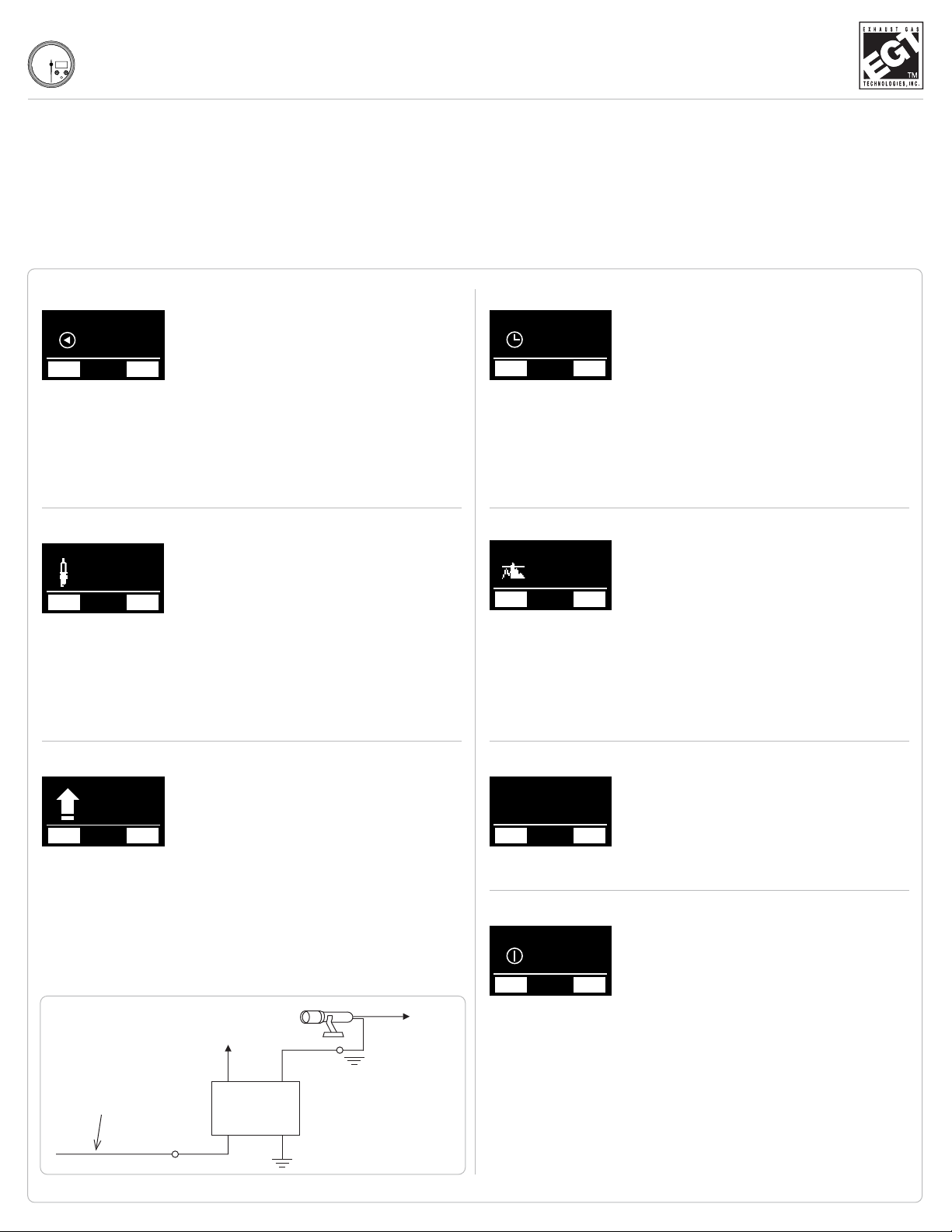
Playback Speed
PRESS AND HOLD PEAK button to edit settings.
HIGHLIGHT desired playback speed with MENU and PEAK
buttons.
After a small delay, the highlighted selection will save.
1:1 plays back in real time.
1:3 plays back in 1/3 time.
PRESS MENU button to open main menu.
PRESS and hold PEAK button to enter Option Settings.
TOGGLE through the following options with MENU and PEAK
buttons:
MENU BUTTON: SETUP
1
2
3
Recording Time
PRESS AND HOLD PEAK button to edit settings.
HIGHLIGHT desired length of recording with MENU and
PEAK buttons.
After a small delay, the highlighted selection will save.
1 minute = 100 samples/second.
5 minutes = 20 samples/second.
10 minutes = 10 samples/second.
20 minutes = 5 samples/second.
1
2
3
Recording Threshold (RPM)
When set at 0, recording starts on Remote or
PEAK button press/hold. When set past 0, button
press/hold delays recording start until RPM reach-
es selected threshold.
LED blink: waiting to reach set RPM.
LED solid: actively recording.
PRESS AND HOLD PEAK button to edit settings.
MOVE pointer to desired RPM setting with MENU and
PEAK buttons.
After a small delay, the selected RPM setting will save.
Pulses per Revolution (PPR)
PRESS AND HOLD PEAK button to edit settings.
HIGHLIGHT desired PPR setting with MENU and PEAK
buttons.
After a small delay, the highlighted selection will save.
1
2
3
See Figure 1 (page 3) to determine the correct
PPR setting for your application.
Restore Defaults
PRESS AND HOLD PEAK button to access settings.
PRESS AND HOLD YES button to restore factory settings.
(Press and hold NO to exit the menu.)
1
2
For troubleshooting and technical support, the
factory default settings can be restored.
TX-3 (Playback Tach) Instructions (4-1/2”)
1
2
3
1
2
3
MENU
RESTORE
DEFAULTS
PREV NEXT
MENU
PULSE PER
REVOLUTION
PREV NEXT
MENU
RECORDING
TIME
PREV NEXT
MENU
RECORDING
THRESHOLD
PREV NEXT
Help
PRESS AND HOLD PEAK button to view data.1
Displays contact info and rmware version.
For assistance, please contact us:
Exhaust Gas Technologies
1-800-348-4678
www.exhaustgas.com
MENU
?
HELP
PREV NEXT
MENU
PLAYBACK
SPEED
PREV NEXT
MENU
RPM SET POINT
PREV NEXT
MENU
RPM SET POINT
PREV NEXT
RPM (Trigger) Set Point
PRESS AND HOLD PEAK button to edit settings.
MOVE pointer to desired RPM setting with MENU and
PEAK buttons.
After a small delay, the selected RPM setting will save.
1
2
3
Sets RPM where relay wire will activate relay
or other connected device. Below RPM set
point, trigger wire will be open oat. When
RPM passes set point, trigger wire will pull to
ground.
GREEN WITH STRIPE
+12V
ATTENTION:
Coil resistance
must be 80
OHMS or greater.
Figure 2. Relay Wiring Schematic
86 30
85 87
+12V

TX-3 (Playback Tach) Instructions (4-1/2”)
PLAYBACK MENU
REW: Hold to rewind. Press for frame-by-frame.
PLAY/PAUSE: Play/pause run.
END: Exit run. Run stores until next recording.
FF: Hold to fast-forward. Press for frame-by-
frame.
PRESS MENU button to open main menu.
PRESS AND HOLD MENU button to begin playback. Gauge
will play run back at set playback speed (1:3 or 1:1).
TOGGLE through options with MENU and PEAK buttons.
1
2
3
The playback tachometer can only store 1 run
at a time. A run will remain saved until a new
run is recorded.
The tachometer will record for the set amount of
time (1, 5, 10, or 20 minutes).
PRESS AND HOLD remote button or PEAK button for 2
seconds.
Recording will start and LED will light up solid blue.
If threshold RPM is set up, the blue LED will ash when the
button is pressed, and will solidify when threshold RPM is
reached and recording starts.
1
2
3
Recording a Run
CONTACT US
Exhaust Gas Technologies Inc.
Tech Line 1-909-548-8100
www.exhaustgas.com
Distributor-Based
(Single-Coil)
Wasted-Spark
(Distributorless)
(Coil Packs)
Coil - On - Plug
(COP)
OEM ECU
Connection
Aftermarket ECU
Connection
12 Cyl (4-Stroke) 6 PPR 1 PPR 0.5 PPR 6 PPR 6 PPR
10 Cyl (4-Stroke) 5 PPR 1 PPR 0.5 PPR 5 PPR 5 PPR
8 Cyl (4-Stroke) 4 PPR 1 PPR 0.5 PPR 4 PPR 4 PPR
6 Cyl (4-Stroke) 3 PPR 1 PPR 0.5 PPR 3 PPR 3 PPR
4 Cyl (4-Stroke) 2 PPR 1 PPR 0.5 PPR 2 PPR 2 PPR
2 Cyl (4-Stroke) 1 PPR 1 PPR 0.5 PPR 1 PPR 1 PPR
1 Cyl (4-Stroke) 0.5 PPR 1 PPR 0.5 PPR 0.5 PPR 0.5 PPR
3 Cyl (2-Stroke) 3 PPR 3 or 6 PPR 1 PPR 3 or 6 PPR 3 or 6 PPR
2 Cyl (2-Stroke) 2 PPR 2 PPR 1 PPR 2 PPR 2 PPR
1 Cyl (2-Stroke) 1 PPR 2 PPR 1 PPR 1 PPR 1 PPR
Figure 1. Determining PPR
MENU
PLAYBACK
SPEED
PREV NEXT
RPM
0
RECORDING
END


