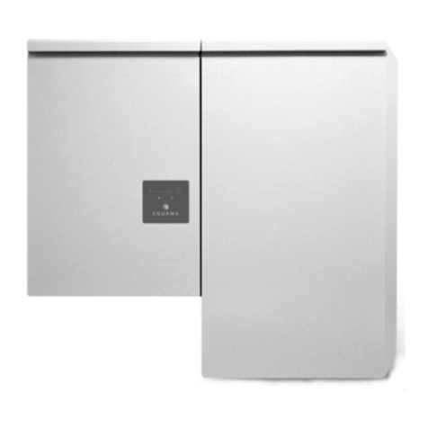
Eguana AC05U-PP Max Installation and operation manual

DO 86073Rev1
AC05U-PP / -SP Max & ACB05-PB Max
Installati n & Startup Manual
F r use nly with battery m dels
•
Pyl ntech US3000C

DO 86073Rev1
Revisi n
Date
Status
Auth r
C mments
1.0
26.July.2022
Draft
RWM
Initial release

DO 86073Rev1
IMPORTANT SAFETY INSTRUCTIONS
SAVE THESE INSTRUCTIONS
The ESS c mp nents described within this manual are intended t be used as part f the Ev lve LFP Max Energy St rage
system and installed per all l cal building c des and regulati ns in additi n t the Nati nal Electrical C de, ANSI/NFPA 70
(f r US) and Canadian Electrical C de (f r Canada).
The f ll wing sub-assembly c mp nents are c vered within this d cument:
ACB05U-PP Master PCS system
ACB05U-SP Sync PCS system
Ev lve PB Battery system
CAUTION: Hazardous Voltages! This inverter contains hazardous voltage and energy that may be lethal. It
may nly be installed by qualified pers nnel wh have read this manual and are familiar with its perati n and
hazards. The f ll wing safety pr cedures sh uld be f ll wed:
Only c nnect the PCS cabinet t a c mpatible electrical service as defined in the m del specificati ns. The PCS must be
c nnected t a dedicated branch circuit in the main electrical panel.
An external disc nnect switch shall be pr vided in the end installati n by thers f r the AC Grid utput circuit.
CAUTION! This e uipment contains high energy lithium batteries. Qualified and trained pers nnel sh uld
wear pr tective cl thing and equipment when w rking inside the battery cabinet and/ r with battery m dules.
CAUTION! The batteries provided with this system must be charged only by the PCS included as part of the
energy storage system. D n t attempt t charge batteries with any ther charger device r c nnect any
devices directly t the DC battery bus.
Ensure pr per electrical gr unding in acc rdance with c de requirements.
Ensure pr per airfl w path f r active c ling.
Never perate system in a manner n t described by this manual.
Only qualified pers nnel sh uld service this pr duct.
Ensure all c vers are securely fastened after installati n is c mplete.
This pr duct must be st red ind rs in an envir nmentally c nditi ned l cati n pri r t installati n, pr tected fr m rain
and exp sure t any hazard us chemicals.
D n t attempt t perate this pr duct if there is any physical evidence f damage t any f the cabinets r internal
c mp nents.
CAUTION! This e uipment is heavy. Mechanical lifts are rec mmended f r safe installati n.
California Proposition 65
WARNING! This pr duct can exp se y u t chemicals including bis (2-ethylhex-yl)phthalate, which is kn wn t
the State f Calif rnia t cause birth defects r ther repr ductive harm. F r m re inf rmati n g t
https://www.p65warnings.ca.gov/.

TABLE OF CONTENTS
1 SAFETY ......................................................................................................................................................................................... 1
1.1
I
N CASE OF EMERGENCY
.............................................................................................................................................................................. 1
1.2
B
ATTERY MODULE SAFETY PRECAUTIONS
................................................................................................................................................. 1
1.3
G
ENERAL SAFETY PRECAUTIONS
................................................................................................................................................................ 2
1.4
D
ISPOSAL AND
R
ECYCLING
........................................................................................................................................................................ 2
2 INTRODUCTION .......................................................................................................................................................................... 3
2.1
A
BOUT THIS
M
ANUAL
–
T
ARGET
A
UDIENCE
............................................................................................................................................ 3
2.2
I
NSTALLATION
P
LANNING
&
S
YSTEM
C
OMMISSIONING
-
S
UPPORTING
D
OCUMENTS
......................................................................... 3
2.3
G
LOSSARY
.................................................................................................................................................................................................... 3
2.4
P
RODUCT MARKINGS
................................................................................................................................................................................... 3
2.5
S
PECIAL TOOLS
&
HARDWARE
................................................................................................................................................................... 3
2.6
I
NITIAL
I
NSPECTION OF
M
ATERIAL
L
IST
–
TOP LEVEL SYSTEM COMPONENTS
........................................................................................ 4
2.6.1 LFP Max install kit – mechanical parts and manuals.......................................................................................................... 5
2.6.2 LFP Max install kit – battery cables ......................................................................................................................................... 6
3 INSTALLATION SITE PREPARATION .................................................................................................................................... 7
3.1
O
VERVIEW OF
PCS
AND
B
ATTERY COMPONENTS
................................................................................................................................... 7
3.2
I
NSTALLATION
A
REA
R
EQUIRED TO
W
ALL
M
OUNT THE
ESS: ............................................................................................................... 7
4 PCS AND BATTERY CABINET WALL-MOUNTING INSTRUCTIONS ............................................................................... 8
5 BATTERY MODULE ASSEMBLY ............................................................................................................................................ 10
5.1
B
ATTERY CABINET GROUND BUS
............................................................................................................................................................. 10
5.2
DC
NEGATIVE
&
POSITIVE POWER BUS TERMINATIONS
........................................................................................................................ 10
5.3
P
REPARING BATTERY MODULES FOR INSTALLATION
............................................................................................................................. 11
5.4
M
OUNTING AND GROUNDING THE BATTERY MODULES IN THE BATTERY CABINET
.............................................................................. 12
5.5
W
IRING THE BATTERY MODULES
............................................................................................................................................................. 13
5.5.1 Battery module C -/+ jumper cable wiring ...................................................................................................................... 13
5.5.2 BMS communication jumper cable wiring .......................................................................................................................... 13
5.5.3 PCS to BMS communication cable ....................................................................................................................................... 14
6 SYSTEM ELECTRICAL WIRING .............................................................................................................................................. 15
6.1
AC
POWER CONNECTIONS
...................................................................................................................................................................... 15
6.2
E
XTERNAL
AC
C
IRCUIT
P
ROTECTION
D
EVICE
....................................................................................................................................... 15
6.3
C
HASSIS
G
ROUNDING
.............................................................................................................................................................................. 16
7 BATTERY MODULE BMS DEFINITIONS AND OPERATING STATES ............................................................................. 16
8 ESS STARTUP PROCEDURE .................................................................................................................................................. 17
8.1
S
YSTEM OPERATION
................................................................................................................................................................................. 17
9 PCS DISPLAY PANEL .............................................................................................................................................................. 18
9.1
LED
D
ISPLAY
I
NDICATORS
...................................................................................................................................................................... 18
9.2
PCS
DISPLAY PANEL INDICATOR SUMMARY
.......................................................................................................................................... 18
9.3
S
ERVICE
B
UTTON
...................................................................................................................................................................................... 18
9.4
B
ACKUP
P
OWER
O
PERATION
................................................................................................................................................................. 19
9.4.1 Backup Power isplay Modes ............................................................................................................................................... 19
9.5
R
ESTARTING THE BATTERY SYSTEM AFTER LOW BATTERY SHUTDOWN
............................................................................................. 20
10 MAINTENANCE & SERVICE .................................................................................................................................................. 20
11 SERVICEABLE PARTS – BATTERY MODULE REMOVAL/REPLACEMENT ................................................................ 20
12 TROUBLESHOOTING ............................................................................................................................................................ 21
13 DECOMMISSIONING THE ESS ............................................................................................................................................. 21

14 SPECIFICATIONS.................................................................................................................................................................... 22
Table 1: PCS Electrical / Mechanical Ratings ............................................................................................................................... 22
Table 3: Battery Cabinet Electrical / Mechanical Ratings ......................................................................................................... 23
Table 4: Battery Cabinet Field Wiring Ratings – AWG / Torque ........................................................................................... 23
14.1
UL
1741
SA
G
RID
S
UPPORT
U
TILITY
I
NTERACTIVE
I
NVERTER
S
PECIFICATIONS
.......................................................................... 24
Table 5: UL1741 SA grid support functions. ................................................................................................................................ 24
Table 6: SA9 Low and high voltage ride through settings. ..................................................................................................... 24
Table 7: SA10 Low and high frequency ride through settings. ............................................................................................. 25
Table 8: SA11 Ramp rate settings. .................................................................................................................................................. 25
Table 9: SA12 Specified power factor settings. .......................................................................................................................... 26
Table 10: SA13 Volt VAR Mode ....................................................................................................................................................... 27
Table 11: SA14 Frequency-Watt settings. ................................................................................................................................... 28
Table 12: SA15 Volt-Watt Settings. ............................................................................................................................................... 28
14.2
T
HERMAL PERFORMANCE
:
C
HARGE
/
D
ISCHARGE
C
URVES
.............................................................................................................. 29

1
1 Safety
The c mp nents described by this manual are intended t be used as part f an energy st rage system and installed per all
l cal building c des and regulati ns in additi n t the Nati nal Electrical C de, ANSI/NFPA 70 (f r US) and Canadian
Electrical C de (f r Canada).
Thr ugh ut this manual, the f ll wing symb ls will be used t highlight imp rtant inf rmati n and pr cedures:
Symbol
Definition
Symbol
Definition
WARNING! A dangerous voltage or other
condition exists. Use extreme caution
when performing these tasks.
Meter measurement required.
AUTION! This information is critical to
the safe installation and or operation of the
inverter. Follow these instructions closely.
T rque rating critical t perati n.
NOTE: This statement is important. Follow
instructions closely.
L gin t the rem te m nit ring system f r
perating status
Gr und, GND, PE
1.1 In case of emergency
In all cases:
•
If safe t d s , switch ff the AC breakers (external t the system).
•
C ntact the fire department r ther required emergency resp nse team.
•
Evacuate the area, and if applicable, f ll w y ur emergency evacuati n plan if thers are in pr ximity t the
installed l cati n.
In case of fire:
•
When safe, use a fire extinguisher suitable f r use; including A, B, and C dry chemical fire extinguishers r carb n
di xide extinguishers.
In case of flooding:
•
Stay ut f water if any part f the system r wiring is submerged.
•
D n t attempt t perate batteries that have been submerged in water even after they have been dried.
In case of unusual noise, smell or smoke:
•
If safe t d s , ventilate the area.
1.2 Battery module safety precautions
This pr duct is integrated with Pylt ntech US3000C series battery m dules. Refer t the Pyl ntech pr duct manual f r
c mplete safety instructi ns regarding handling f battery m dules.
EMS

2
1.3 General safety precautions
Important! Installati n, service, and perating pers nnel must read this d cument in its
entirety, and bserve all safety and installati n pr cedures as described in this manual.
Never perate system in a manner n t described by this manual.
Only qualified pers nnel sh uld service this pr duct.
Ensure all c vers are securely fastened after installati n is c mplete.
Pers nal Pr tective Equipment (PPE) in c mpliance with l cal w rk place safety standards must be
w rn when w rking inside the cabinet.
Risks of Fire
D n t exp se the system t temperatures exceeding 60 degrees Celsius.
Av id installati n in direct sunlight.
D n t st re bjects n t p f the cabinet.
D n t bstruct the airfl w paths f the cabinet air intake.
D n t bstruct the exhaust f cabinet exhaust.
D n t st re c mbustible bjects and c rr sive chemicals directly adjacent t the system.
Risks of Shock
WARNING! Hazardous Voltages.
The Inverter contains hazardous voltage and energy that may be lethal
.
It may nly be installed by qualified pers nnel wh have read this manual and are familiar with its perati n
and hazards.
Only c nnect the PCS cabinet t a c mpatible electrical service as defined in the m del specificati ns. The
PCS must be c nnected t a dedicated branch circuit in the main electrical panel.
Ensure pr per electrical gr unding in acc rdance with c de requirements.
CAUTION! Both
AC
and
DC
voltage sources are terminated inside this e uipment. Each circuit must be
individually disconnected before servicing
Risks of Damage
The PCS is c nfigured f r the Pyl ntech US3000C battery m dule nly. D n t attempt t c nnect any ther
battery t the system.
D n t c nnect any ther l ads directly t the battery p wer bus.
D n t dr p, tip, r
puncture the cabinet during transp rt and installati n. Visible damage t the cabinet
and/ r internal c mp nents sh uld be rep rted t the manufacturer immediately.
D n t st re this system f r peri ds l nger than six m nths with ut a battery maintenance charge. This may
result in permanent damage t the batteries.
1.4 Disposal and Recycling
D n t disp se f the system r any f the c mp nents within the cabinet. Batteries, electr nics, cables, and
metal parts are recyclable. C nsult y ur municipal waste management auth rity t determine required meth ds
f c mp nent recycling.

3
2 Introduction
2.1 About this Manual – Target Audience
This manual is intended t be used by qualified service and installati n pers nnel f r the purp ses f pr duct installati n.
This manual c ntains instructi ns f r the installati n f Eguana Ev lve™ energy st rage c mp nents required t assemble
the Ev lve LFP Max ; including the CB. This pr duct is permanently wired t the h me electrical service, and must be
installed by a licensed electrician nly.
2.2 Installation Planning & System Commissioning - Supporting Documents
The Ev lve LFP Max energy st rage system is perated by the Ev lve Hub. Please c nsult the Ev lve Hub Installati n
Manual f r full installati n planning details, including c nduit lay ut plans and sample single line diagrams f r a c mplete
s lar plus st rage system installati n. The Ev lve Hub installati n manual als describes in m re detail the vari us
perating m des and c nfigurati ns f r AC c upled PV s lar plus st rage systems.
A c mplete list f Installer res urces is available at www.eguanatech.c m under the Ev lve™ pr duct banner.
2.3 Glossary
2.4 Product markings
The ratings label is l cated n the b tt m face f each
cabinet. The serial number / date c de labels f r the
system are l cated as sh wn (right) with the fr nt
c vers rem ved.
2.5 Special tools & hardware
The f ll wing t ls are required t c mplete the
installati n f the ESS:
•
T rque wrench
•
17mm s cket wrench (DC- main p wer
c nnecti n).
•
10mm s cket wrench (battery +/- m dule
p wer c nnecti ns).
•
3/8” s cket wrench (DC+ main p wer
c nnecti n).
•
L ad bearing hardware f r wall bracket
m unting. 5/16” (M8)
Term Definiti n Term Definiti n
AC
/ DC
Alternating Current
/ Direct Current
LED
Light Emitting Di de
ARC
Aut Rec very Circuit
NC
/ NO
N rmally Cl sed
/ N rmally Open
CPU
Central Pr cessing Unit
PCS
P wer C ntr l System (Inverter)
EMC
Energy Management C ntr ller
PE
Pr tective Earth
EMS
Energy Management System
PV
Ph t
-
V ltaic
ESD
Electr static Discharge
RF
Radi Frequency
ESS
Energy St rage System
SOC
State Of Charge (Battery)
GND
Gr und
SOH
State f Health (Battery)
All cabinets:
ratings label
PCS cabinet:
s/n, date c de
Battery cabinet:
s/n, date c de

4
2.6 Initial Inspection of Material List – top level system components
The system c mp nents supplied with the system are sh wn bel w. Each c mp nent sh uld be inspected visually f r any
damage that may have been caused by shipment. If damage is present, please c ntact y ur l cal distribut r.
Item Eguana P/N Description
1 ACB05U-PP/SP Max PCS cabinet (and c ver)
2 ACB05-PB Max Battery Cabinet (and c ver)
3* --------- Wall m unt rail – PP m del
3* --------- Wall m unt rail – SP m del
4 US3000C 4 battery m dules
5 LFP Max install kit Assembly parts kit, cables, and manuals.
1
2
3
4
5
Figure
1
: Top level system
components.

5
2.6.1 LFP Max install kit – mechanical parts and manuals
Item Qty Eguana P/N Description
Battery Cabinet
1 1 PB kit Incl. cabinet c upler assembly, tw levelling brackets, and tw plugs
2 8 801003244 Adhesive backed battery m dule pads
3 1 801003757 Battery rack partiti n bracket (includes attached battery retaining clip 801003044)
PCS Cabinet
4 1 LP Max kit
Incl. levelling bracket, cabinet c upler end plate, plug, and PCS
-
BMS c mmunicati n
cable.
- 1 D c 82013 Ev lve LFP Max Installati n and Startup Manual
- 1 D c 58159 Ev lve LFP Max System Owner’s Manual
4
SP/PP Max kit
US3000C
PB
Max
kit
1
2
3
8x
Figure
2
: LFP Max install kit
-
mechanical parts.

6
2.6.2 LFP Max install kit – battery cables
Item Qty Eguana P/N Description Pylon p/n
1 2 801003792 BMS jumper sh rt 210 mm WI0SRJ458025
2 1 801003794 BMS jumper l ng 700 mm WI0SUS300002
3 4 801003791 Chassis GND cable GRN/YEL 1 m WI0GUS300001
BMS
GND
1
2
3
Figure
3
: LFP Max install kit
-
battery cables.

7
3 Installation Site Preparation
Bef re installing the pr duct, read all instructi ns and warnings in this manual. This pr duct is wall-m unted nly, and can
be installed b th utd rs (in c mpliance with NEMA Type 3R installati ns) and ind rs, either attached r detached
garages, and ind r l cati ns m re than 5 feet fr m dwelling units. This pr duct is n t t be installed in habitable spaces.
C nsult l cal building c des f r m re details.
AUTION! All electrical installation work should be performed in accordance with local building and electrical codes.
WARNING! Isolate the PCS from all energy sources prior to electrical installation by means of disconnects, breakers
or connectors. Failure to properly isolate either AC or C sources may result in serious injury or death. This system
will generate an AC voltage at the off-grid terminals when C source is applied.
AUTION! The P S cabinet weighs up to 145 lbs. (65 kg), and the battery cabinet weighs up to 320 lbs. (145
kg) with four battery modules installed. Handle with care. The wall t which the system is m unted must be
l ad-bearing rated acc rding t the l cal building c de. Mechanical lifts are rec mmended t p siti n cabinets n the wall
bracket.
NOTE: All interc nnecting cables are limited in length, and designed specifically f r adjacent cabinet m unting using
the manufactured wall brackets.
CAUTION! o not install in direct sunlight. Battery performance is dependent upon operating ambient temperature.
Radiant heat absorbed in direct sunlight will greatly reduce the performance of the battery, and will prematurely
cause degradation of the display indicator panel on the PCS cabinet. The battery modules are rated for operating
temperature range between -10C to +50C.
NOTE: ESS systems installed ind rs may require the installati n f a sm ke alarm r heat detect r specific f r ESS
use. C nsult the l cal building c de f r m re details.
NOTE: This pr duct was n t evaluated in seismic envir nments.
NOTE: All external wiring must be pr tected by metallic c nduit, and all c nduit fittings installed n the ESS
cabinets must be rated Type 3R r better.
3.1 Overview of PCS and Battery components
1. The f rced air c ling f the PCS cabinet is designed t fl w air fr m b tt m t t p.
2. Wall m unting hardware n t
included. The l ad-bearing
wall bracket is pr visi ned f r
M8 hardware. Levelling
brackets are pr visi ned f r
M5 hardware.
3.2 Installation Area Required
to Wall Mount the ESS:
The physical installati n f the cabinets
requires lay ut planning and installati n
f the system c mp nents in the
available installati n space. The
rec mmended installati n height is
driven by the viewing angle f the
display panel n the PCS cabinet.
Figure
4
: Installation clearances for the Evolve LFP Max energy storage
system (ACB05U-PP model shown).

8
4 PCS and Battery Cabinet Wall-Mounting Instructions
N te: The f ll wing instructi ns apply t the –SP m del.
The -PP m del f ll ws the same instructi n set with the
battery cabinet placed t the left f the PCS cabinet.
1. M unt the wall rail t the wall. Use the available sl t pattern t
m unt t a l ad-bearing structure rated f r the weight f the final
system. The sl ts acc mm date a M8 (5/16”) b lt diameter.
IMPORTANT! Wall-stud m unting: A minimum f three wall
studs spanned within the width f the m unting rail are
required. A minimum f tw m unting b lts are required per stud
(t p/b tt m).
2. (n t sh wn) Rem ve the battery cabinet fr m the packaging, and
stand the cabinet upright. Rem ve the fr nt c ver.
3. M unt the tw leveling brackets t the back side f the cabinet.
Each side f the cabinet must have a rubber washer in direct
c ntact with the cabinet wall.
4. Lift the battery cabinet nt the wall m unt bracket, aligning the
wall h ks at the rear f the cabinet with the sl ts n the l ad-
bearing face f the bracket.
5. Slide the battery cabinet t wards the right end f the bracket t
all w f r clearance f r the PCS cabinet.
6. Fr m the rear side f the cabinet, adjust the uter wingnuts n the
levelling brackets until the cabinet is vertically plumb (level) t the
wall.
1
3
4
3
9
8
Figure
5
: Wall
-
mounting the cabinets.
6
-
P
P
-
SP

9
7. Rem ve the PCS cabinet fr m its packaging and
stand upright. (n t sh wn). Rem ve the fr nt
c ver.
8. Assemble and m unt the single l wer-center
leveling bracket as sh wn in steps 3 and 4 ab ve.
CAUTION! The PCS cabinet is heavy.
Mechanical lift r tw pers ns rec mmended.
9. Lift the PCS cabinet nt the wall m unting bracket.
10. Slide the PCS cabinet t the left such that it aligns
with the alignment tab n the m unting bracket.
11. Fr m the rear side f the cabinet, adjust the uter
wingnut n the single levelling bracket until the
cabinet is vertically plumb (level) t the wall. (see
image – step 6).
12. Insert the PCS cabinet c upling gasket between the
tw cabinets (l wer-fr nt). Slide the battery cabinet
t wards the left until mating t the gasket.
13. Place the c upling plate inside the PCS cabinet and
insert the f ur m unting b lts and washers thr ugh
t the battery cabinet side.
14. Place star washers n the b lts n the battery side
f the cabinet.
15. M unt the battery cabinet side c upling plate, and
fasten with the l ck nuts. T rque t 10 – 15 in-lbs.
WARNING! The mounting bolts of the flange
assembly are required to be fully secured, as
they provide the chassis grounding for the battery
cabinet. Torque nuts as shown in the specification
tables provided in this manual.
16. Continuity test: Check the c ntinuity
between the cabinets using an Ohm meter. The
test reading must be zer Ohms at a bare metal
p int inside each f the PCS and battery cabinets.
17. Install the cabinet c upler end plate (see- LP kit) t
seal the h le n the battery cabinet.
18. Opti nal: (This is n t a l ad bearing anch r –
anch red c nduit runs t the PCS are satisfact ry).
Install screws in leveling plates f r PCS and battery
cabinets by inserting a screwdriver thr ugh the h le
n the backside f the cabinets.
19. Plug h le n back f cabinet using by inserting the
h le plug fr m the fr nt side.
Opti nal (
hardware
n t included)
12
16
thru
18
19
17
10
Figure
6
: PCS cabinet and inter
-
cabinet coupler installation.

10
5 Battery Module Assembly
The f ll wing instructi ns include:
•
Interc nnecti n f the PCS DC and c mmunicati n cables t
the battery cabinet.
•
Preparati n and assembly f the battery cabinet m dules and
internal wiring.
Note: Overcurrent protection of the C source is provided
internally as part of the integrated battery system. No
external C disconnect is required.
5.1 Battery cabinet ground bus
CAUTION! A tor ue wrench is re uired to ensure the
power cables are terminated to their specifications. Over-
t rque can damage the DC breaker and/ r strip the threads
n the c pper bus bar p sts. Under-t rque can result in an arc fault
hazard, and risk f fire. Damage as a result f impr per terminati n is
n t c vered by the manufacturer warranty.
1. M unt the f ur gr und wires pr vided in the battery m dule
gr unding kit int the 4-p siti n gr und distributi n bl ck.
5.2 DC negative & positive power bus terminations
N te; MAX -S m del sh wn. See fr nt view f the MAX-P
m del bel w.
2. R ute the DC- cable fr m the DC- bus t the battery
disc nnect DC- p st. T rque the nut t 35 in/lbs.
3. R ute the DC+ cable fr m the DC+ bus t the
battery disc nnect DC+ p st. T rque the nut t 35 in/lbs.
P/N
Description
-----
PCS DC
-
battery disc nnect cable
-----
PCS DC+ battery disc nnect cable
1
3
2
Figure
7
: Battery
cabinet module grounding wires and
C negative/positive terminations

11
5.3 Preparing battery modules for
installation
The PCS cabinet is n t sh wn in the f ll wing steps.
CAUTION! Ensure the battery m dule p wer
switches are in the OFF p siti n thr ugh ut
the f ll wing pr cedure.
N te: Observe the r tati n f the m dules
n the l wer and upper racks. The l wer
rack is r tated such that the chassis gr und
terminal is at the b tt m f the m dule, while the
upper rack chassis gr und terminal is at the t p.
1. (n t sh wn) Rem ve a battery fr m its
packaging. Rem ve the rackm unt ears, if
supplied with the battery.
2. Attach tw adhesive-backed m dule pads
(included in the battery m dule hardware kit)
t the battery m dules as sh wn. F r the
l wer rack f m dules, the pads are installed
n the t p face f the battery. F r the upper
rack, the pads are installed n the b tt m
face f the battery.
u
pper rack
l wer
rack
Figure
8
: Attaching adhesive pads to the battery modules.

12
5.4 Mounting and grounding the battery modules in the battery cabinet
1. Slide the l wer rack battery int the cabinet as sh wn, and c nnect the gr und cable t the ring terminal gr und
c nnect r n the battery m dule as sh wn.
2. Push the m dule inward until making c ntact with the rear face f the cabinet.
3. Repeat steps 1 and 2 ab ve with the 2
nd
l wer rack m dule.
4. M unt the l wer rack retaining clip.
5. Install the battery rack partiti n bracket as sh wn using the tw M5 keps nuts pr vided.
N te: Rem ve the retaining clip fr m the bracket if m unted n the partiti n bracket bef re pr ceeding with the
f ll wing steps:
6. Repeat steps 1 thru 3 ab ve with the upper level battery rack.
7. M unt the tw upper rack retaining clips.
2
4
5
3
6
Upper rack
l wer rack
1
7
Figure
9
: Installing and grounding the battery modules.

13
5.5 Wiring the battery modules
F ll w the battery m dule p wer and
c mmunicati n jumper wiring bel w.
5.5.1 Battery module C -/+ jumper cable
wiring
The battery cables are fact ry terminated at the
DC- and DC+ bus. All cables are the same length.
C nnect each m dule (push-t -click) c nnect r
as sh wn (right).
5.5.2 BMS communication jumper cable
wiring
Install the cables in the f ll wing sequence.
IMPORTANT! All m dule interc nnecting
BMS jumpers terminate at the [Linkp rt]
terminals. N te the Linkp rt reference, 0 an 1, f r
each p rt c nnecti n.
1. Terminate the BMS jumper cable C2 between
batteries #2 - 3.
2. Terminate the BMS jumper cables C1
between batteries #1-2 and #3-4.
Ref
P/N
Description
Pylon p/n label
C1 #3792
BMS jumper
sh rt 210 mm WI0SRJ458025
C2 #3794
BMS jumper
l ng 700 mm WI0SUS300002
Figure
10
: Installing the battery jumper cables.

14
5.5.3 PCS to BMS communication cable
This cable is specific t the battery m del. Refer t the instructi n that applies nly t the battery m dule suppled.
Terminate the PCS-BMS cable in battery #1 as sh wn bel w. This battery is herein referred t as the “Master” battery
m dule. All ther m dules sync t the master.
1. Terminate the PCS – BMS / C ns le Y cable jumper in the [A/CAN] and [C ns le] p rts f battery #1.
2. R ute the ther end f the cable thr ugh the PCS p rt h le and terminate in the cable in the [BMS OUT] p rt.
BMS OUT
1
US3000C
#3810
Figure
11
: PCS to BMS communication cable connection.

15
6 System Electrical Wiring
Note: This pr duct is capable f pr viding utility interactive and
islanded back up p wer, and can be AC c upled t a utility interactive
ph t v ltaic inverter. Wiring meth ds must be in acc rdance with
l cal electrical c des. The installer is resp nsible f r ensuring that ver-
current pr tecti n is installed and sized appr priately f r the AC grid
and ff-grid utput circuits, in acc rdance with the Nati nal Electrical
C de, ANSI/NFPA 70, Canadian Electrical C de and l cal c des.
All field wiring c nnecti ns t the battery system are at the PCS cabinet nly.
The kn ck ut l cati ns f r c nduit entry int the PCS are categ rized as AC
p wer and signal level circuits.
IMPORTANT! Drilling holes anywhere in the battery or PCS cabinet
renders the warranty null and void. Use the kn ck uts pr vided at the
b tt m face f the PCS cabinet nly! D n t drill h les anywhere in the
battery system. Use c nduit fitting reducers, if applicable.
6.1 AC power connections
Note: The PCS pr vides galvanic separati n between AC and
DC S urces.
AUTION! To reduce the risk of fire, connect only to a
dedicated circuit provided with appropriate branch circuit over-
current protection in accordance with local electrical codes.
WARNING! Improper connection of the wiring panel may
result in equipment damage and cause personal injury.
isconnect all AC and C Sources prior to installation.
Note: The AC utput’s Neutral terminal is n t b nded t
gr und. The Neutral is c nnected t gr und when perating in
backup (stand-al ne) m de.
AC Grid Port:
1. Terminate the AC grid c nnecti n wires as f ll ws:
L = Line
N = Neutral
PE = Gr und.
6.2 External AC Circuit Protection Device
An external AC circuit pr tecti n device, either breaker r fused disc nnect, that is lates all ungr unded c nduct rs, shall
be pr vided by thers f r the AC Grid utput circuit. F r utd r wall m unt installati ns, the disc nnect must be rated f r
utd r use and include fuse pr tecti n f ungr unded c nduct rs (2 p le). The maximum fuse / breaker rating f r the
external disc nnect is determined by the use applicati n f the ESS:
Grid interactive nly perati n (with ut backup): 50 Amp
Grid interactive & backup perati n: 60 Amp
PE
N
L
Grid
PCS cabinet
–
b tt m view
AC p wer
Signal
Figure
12
:
PCS knockout detail.
Figure
13
:
AC power connections.
This manual suits for next models
2
Table of contents
Other Eguana Switch manuals
Popular Switch manuals by other brands

Endress+Hauser
Endress+Hauser Liquiphant M FTL50 operating instructions
S&C
S&C Alduti-Rupter Switches Outdoor Distribution Installation and operation
NETGEAR
NETGEAR 748TP Hardware installation guide
Western Telematic
Western Telematic AFS-16-1 user guide
MaxiiNet
MaxiiNet Vi30005 installation manual
Ask
Ask ADSW0012M1 user manual
Linksys
Linksys FENSK05 - EtherFast Network Starter user guide

Dynex
Dynex DX-B7PORT Guía de instalación

LEGRAND
LEGRAND 3 109 77 quick start guide
Extreme Networks
Extreme Networks Summit Summit24 Installation and user guide
Acuity Brands
Acuity Brands nLight UNITOUCH user manual
Sun Oracle
Sun Oracle ES1-24 Safety and compliance guide
