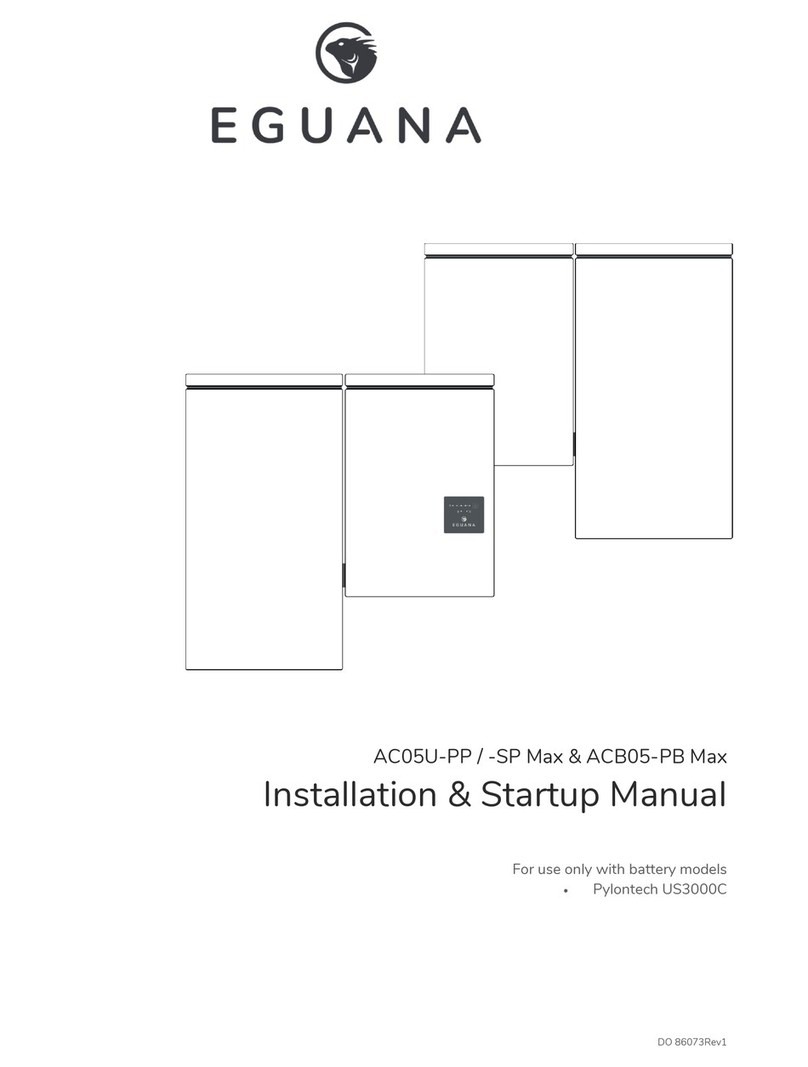
Eguana Evolve LFP Installation and operation manual

DO 82013Rev1
Evolve LFP
Installation & Startup Manual
For use only wit battery models
•Pylontec US3000 /US3000C

DO 82013Rev1

DO 82013Rev1
IMPORTANT SAFETY INSTRUCTIONS
SAVE THESE INSTRUCTIONS
T is manual contains important instructions for t e Eguana Evolve™ LFP, including t e Power Control System (PCS) and base
model battery cabinet installation and operation, erein defined as t e ESS. T e ESS is expandable wit t e addition of up to two
more battery cabinets. Refer to t is manual in Appendix A for more details if your system contains additional battery capacity
beyond t e base model. T e ESS components described by t is manual are intended to be used as part of an Energy Storage
system and installed per all local building codes and regulations in addition to t e National Electrical Code, ANSI/NFPA 70 (for US)
and Canadian Electrical Code (for Canada).
CAUTION: Hazardous Voltages! This inverter contains hazardous voltage and energy that may be lethal. It may only
be installed by qualified personnel w o ave read t is manual and are familiar wit its operation and azards. T e
following safety procedures s ould be followed:
Only connect t e PCS cabinet to a compatible electrical service as defined in t e model specifications. T e PCS must be connected
to a dedicated branc circuit in t e main electrical panel.
An external disconnect switc s all be provided in t e end installation by ot ers for t e AC Grid output circuit.
CAUTION! This e uipment contains high energy lithium batteries. Qualified and trained personnel s ould wear
protective clot ing and equipment w en working inside t e battery cabinet and/or wit battery modules.
CAUTION! The batteries provided with this system must be charged only by the PCS included as part of the energy
storage system. Do not attempt to c arge batteries wit any ot er c arger device or connect any devices directly to t e
DC battery bus.
Ensure proper electrical grounding in accordance wit code requirements.
Ensure proper airflow pat for active cooling.
Never operate system in a manner not described by t is manual.
Only qualified personnel s ould service t is product.
Ensure all covers are securely fastened after installation is complete.
T is product must be stored indoors in an environmentally conditioned location prior to installation, protected from rain and
exposure to any azardous c emicals.
Do not attempt to operate t is product if t ere is any p ysical evidence of damage to any of t e cabinets or internal components.
CAUTION! This e uipment is heavy. Mec anical lifts are recommended for safe installation.

TABLE OF CONTENTS
1 SAFETY ......................................................................................................................................................................................... 1
1.1
I
N CASE OF EMERGENCY
.............................................................................................................................................................................. 1
1.2
B
ATTERY MODULE SAFETY PRECAUTIONS
................................................................................................................................................. 1
1.3
G
ENERAL SAFETY PRECAUTIONS
................................................................................................................................................................ 2
1.4
D
ISPOSAL AND
R
ECYCLING
........................................................................................................................................................................ 2
2 INTRODUCTION .......................................................................................................................................................................... 3
2.1
A
BOUT THIS
M
ANUAL
–
T
ARGET
A
UDIENCE
............................................................................................................................................ 3
2.2
I
NSTALLATION
P
LANNING
&
S
YSTEM
C
OMMISSIONING
-
S
UPPORTING
D
OCUMENTS
......................................................................... 3
2.3
G
LOSSARY
.................................................................................................................................................................................................... 3
2.4
P
RODUCT MARKINGS
................................................................................................................................................................................... 3
2.5
S
PECIAL TOOLS
&
HARDWARE
................................................................................................................................................................... 3
2.6
I
NITIAL
I
NSPECTION OF
M
ATERIAL
L
IST
–
TOP LEVEL SYSTEM COMPONENTS
........................................................................................ 4
2.6.1 LFP install kit – mechanical parts and manuals ................................................................................................................... 5
2.6.2 LFP install kit – battery cables ................................................................................................................................................... 6
3 INSTALLATION SITE PREPARATION .................................................................................................................................... 7
3.1
O
VERVIEW OF
PCS
AND
B
ATTERY COMPONENTS
................................................................................................................................... 7
3.2
I
NSTALLATION
A
REA
R
EQUIRED TO
W
ALL
M
OUNT
PCS
AND
B
ATTERY
: ............................................................................................. 7
4 PCS AND BATTERY CABINET WALL-MOUNTING INSTRUCTIONS ............................................................................... 8
5 BATTERY MODULE ASSEMBLY ............................................................................................................................................ 10
5.1
B
ATTERY CABINET GROUND BUS
............................................................................................................................................................. 10
5.2
DC
NEGATIVE POWER TERMINAL ASSEMBLY
......................................................................................................................................... 10
5.3
P
REPARING BATTERY MODULES FOR INSTALLATION
............................................................................................................................. 11
5.4
M
OUNTING AND GROUNDING THE BATTERY MODULES IN THE BATTERY CABINET
.............................................................................. 12
5.5
W
IRING THE BATTERY MODULES
............................................................................................................................................................. 13
5.5.1 Battery module DC /+ jumper cable wiring ...................................................................................................................... 13
5.5.2 BMS communication jumper cable wiring .......................................................................................................................... 13
5.5.3 PCS to BMS communication cable ....................................................................................................................................... 14
5.6
DC-
BATTERY MODULE TO CABINET
DC-
CONNECTIONS
..................................................................................................................... 15
5.7
PCS
DC+
POWER AND BREAKER ASSEMBLY WIRING
.......................................................................................................................... 16
6 SYSTEM ELECTRICAL WIRING .............................................................................................................................................. 17
6.1
AC
POWER CONNECTIONS
...................................................................................................................................................................... 17
6.2
C
HASSIS
G
ROUNDING
.............................................................................................................................................................................. 18
6.3
C
OMMUNICATION
W
IRING TO THE
E
NERGY
M
ANAGEMENT
S
YSTEM
–
RJ45
P
IN
-
OUT
.................................................................... 18
6.4
AK1
E
VOLVE
H
UB CONTROL CABLE
...................................................................................................................................................... 18
7 BATTERY MODULE BMS DEFINITIONS AND OPERATING STATES ............................................................................. 19
8 ESS STARTUP PROCEDURE .................................................................................................................................................. 20
8.1
S
YSTEM OPERATION
................................................................................................................................................................................. 20
9 PCS DISPLAY PANEL .............................................................................................................................................................. 21
9.1
LED
D
ISPLAY
I
NDICATORS
...................................................................................................................................................................... 21
9.2
PCS
DISPLAY PANEL INDICATOR SUMMARY
.......................................................................................................................................... 21
9.3
S
ERVICE
B
UTTON
...................................................................................................................................................................................... 22
9.4
B
ACKUP
P
OWER
O
PERATION
................................................................................................................................................................. 22
9.4.1 Backup Power Display Modes ............................................................................................................................................... 22
9.5
R
ESTARTING THE BATTERY SYSTEM AFTER LOW BATTERY SHUTDOWN
............................................................................................. 23
10 MAINTENANCE ....................................................................................................................................................................... 23
11 SERVICEABLE PARTS – BATTERY MODULE REMOVAL/REPLACEMENT ................................................................ 23
12 TROUBLESHOOTING ............................................................................................................................................................ 24

13 SPECIFICATIONS.................................................................................................................................................................... 25
Table 1: PCS Electrical / Mechanical Ratings ............................................................................................................................... 25
Table 2: PCS Field Wiring Ratings – AWG / Torque ................................................................................................................. 26
Table 3: Battery Cabinet Electrical / Mechanical Ratings ......................................................................................................... 26
Table 4: Battery Cabinet Field Wiring Ratings – AWG / Torque ........................................................................................... 26
13.1
UL
1741
SA
G
RID
S
UPPORT
U
TILITY
I
NTERACTIVE
I
NVERTER
S
PECIFICATIONS
.......................................................................... 27
Table 5: UL1741 SA grid support functions. ................................................................................................................................ 27
Table 7: SA9 Low and high voltage ride through settings. ..................................................................................................... 27
Table 8: SA10 Low and high frequency ride through settings. ............................................................................................. 28
Table 9: SA11 Ramp rate settings. .................................................................................................................................................. 29
Table 10: SA12 Specified power factor settings. ....................................................................................................................... 29
Table 11: SA13 Volt VAR Mode ....................................................................................................................................................... 30
Table 12: SA14 Frequency Watt settings. ................................................................................................................................... 31
Table 13: SA15 Volt Watt Settings. ............................................................................................................................................... 31
13.2
T
HERMAL PERFORMANCE
:
C
HARGE
/
D
ISCHARGE
C
URVES
.............................................................................................................. 32
APPENDIX A: BATTERY EXPANSION CABINET INSTALLATION – BATTERIES #5 TO #8 ......................................... 34
A.1
I
NITIAL
I
NSPECTION OF
M
ATERIAL
L
IST
–
TOP LEVEL SYSTEM COMPONENTS
.................................................................................... 34
2.6.1 LFP expansion install kit – mechanical parts .................................................................................................................... 34
2.6.2 LFP install kit – battery cables ................................................................................................................................................ 35
A.2
W
ALL BRACKET INSTALLATION
.............................................................................................................................................................. 36
A.3
M
OUNTING THE CABINET TO THE WALL
................................................................................................................................................. 36
A.4
B
ATTERY MODULE ASSEMBLY
................................................................................................................................................................. 36
A.5
B
ATTERY MODULE WIRING
...................................................................................................................................................................... 36
APPENDIX B: ELECTRICAL BLOCK DIAGRAM – INTERNAL .............................................................................................. 37

1
1 Safety
T is manual contains important instructions for t e Eguana Evolve™ LFP. T e components described by t is manual are intended
to be used as part of an energy storage system and installed per all local building codes and regulations in addition to t e National
Electrical Code, ANSI/NFPA 70 (for US) and Canadian Electrical Code (for Canada).
T roug out t is manual, t e following symbols will be used to ig lig t important information and procedures:
Symbol
Definition
Symbol
Definition
WARNING! A dangerous voltage or other
condition exists. Use extreme caution
when performing these tasks.
Meter measurement required.
AUTION! This information is critical to the
safe installation and or operation of the
inverter. Follow these instructions closely.
Torque rating critical to operation.
NOTE: This statement is important. Follow
instructions closely.
Login to t e remote monitoring system for
operating status
1.1 In case of emergency
In all cases:
•If safe to do so, switc off t e AC breakers (external to t e system).
•Contact t e fire department or ot er required emergency response team.
•Evacuate t e area, and if applicable, follow your emergency evacuation plan if ot ers are in proximity to t e installed
location.
In case of fire:
•W en safe, use a fire extinguis er suitable for use; including A, B, and C dry c emical fire extinguis ers or carbon dioxide
extinguis ers.
In case of flooding:
•Stay out of water if any part of t e system or wiring is submerged.
•Do not attempt to operate batteries t at ave been submerged in water even after t ey ave been dried.
In case of unusual noise, smell or smoke:
•If safe to do so, ventilate t e area.
1.2 Battery module safety precautions
T is product is integrated wit Pyltontec US3000 / US3000C series battery modules. Refer to t e Pylontec product manual for
complete safety instructions regarding andling of battery modules.
EMS

2
1.3 General safety precautions
Important! Installation, service, and operating personnel must read t is document in its entirety,
and observe all safety and installation procedures as described in t is manual. Never operate
system in a manner not described by t is manual.
Only qualified personnel s ould service t is product.
Ensure all covers are securely fastened after installation is complete.
Personal Protective Equipment (PPE) in compliance wit local work place safety standards must be worn
w en working inside t e cabinet.
Risks of Fire
Do not expose t e system to temperatures exceeding 60 degrees Celsius.
Avoid installation in direct sunlig t.
Do not store objects on top of t e cabinet.
Do not obstruct t e airflow pat s of t e cabinet air intake.
Do not obstruct t e ex aust of cabinet ex aust.
Do not store combustible objects and corrosive c emicals directly adjacent to t e system.
Risks of Shock
WARNING! Hazardous Voltages.
The Inverter contains hazardous voltage and energy that may be lethal
. It
may only be installed by qualified personnel w o ave read t is manual and are familiar wit its operation and
azards.
Only connect t e PCS cabinet to a compatible electrical service as defined in t e model specifications. T e PCS
must be connected to a dedicated branc circuit in t e main electrical panel.
Ensure proper electrical grounding in accordance wit code requirements.
CAUTION! Both
AC
and
DC
voltage sources are terminated inside this e uipment. Each circuit must be
individually disconnected before servicing
Risks of Damage
T e PCS is configured for t e Pylontec US3000 / US3000C battery module only. Do not attempt to connect any
ot er battery to t e system.
Do not connect any ot er loads directly to t e battery power bus.
Do no
t drop, tip, or puncture t e cabinet during transport and installation. Visible damage to t e cabinet and/or
internal components s ould be reported to t e manufacturer immediately.
Do not store t is system for periods longer t an six mont s wit out a battery maintenance c arge. T is may result
in permanent damage to t e batteries.
1.4 Disposal and Recycling
Do not dispose of t e system or any of t e components wit in t e cabinet. Batteries, electronics, cables, and metal parts
are recyclable. Consult your municipal waste management aut ority to determine required met ods of component
recycling.

3
2 Introduction
2.1 About this Manual – Target Audience
T is manual is intended to be used by qualified service and installation personnel for t e purposes of product installation.
T is manual contains instructions for t e installation and start up sequence of t e Eguana Evolve™ LFP; including t e PCS and
master battery cabinets. T is product is permanently wired to t e ome electrical service, and must be installed by a licensed
electrician only. T e battery capacity of t is system can be expanded by adding additional cabinets adjacent to t e base battery
cabinet. Refer to Appendix A for battery expansion installation instructions.
2.2 Installation Planning & System Commissioning - Supporting Documents
T e Evolve LFP energy storage system is operated by t e Evolve Hub. Please consult t e Evolve Hub Installation Manual for full
installation planning details, including conduit layout plans and sample single line diagrams for a complete solar plus storage
system installation. T e Evolve Hub installation manual also describes in more detail t e various operating modes and
configurations for AC coupled PV solar plus storage systems.
T e Evolve Hub’s energy management system & gateway requires installer administration and device commissioning prior to
operation of t e Evolve LFP energy storage system. Refer to t e Fleet Installer Administration Guide and t e Evolve Hub Install
and Commission Quick Guide for furt er details.
A complete list of Installer resources is available at www.eguanatec .com under t e Evolve™ product banner.
2.3 Glossary
2.4 Product markings
T e ratings label is located on t e bottom face of eac
cabinet. T e serial number / date code labels for t e system
are located as s own (rig t) wit t e front covers removed.
2.5 Special tools & hardware
T e following tools are required to complete t e installation
of t e ESS:
•Torque wrenc
•17mm socket wrenc (DC- main power
connection).
•10mm socket wrenc (battery +/- module power
connections).
•3/8” socket wrenc (DC+ main power connection).
•
Load bearing ardware for wall bracket mounting.
5/16” (M8)
Term Definition Term Definition
AC
Alternating Current
LED
Lig
t Emitting Diode
ARC
Auto Recovery Circuit
NC
/ NO
Normally Closed
/ Normally Open
CPU
Central Processing Unit
PCS
Power Control System (Inverter)
DC
Direct Current
PE
Protective Eart
EMS
Energy Management System
PV
P oto
-
Voltaic
ESD
Electrostatic D
isc arge
RF
Radio Frequency
ESS
Energy Storage System
SOC
State Of C arge (Battery)
GND
Ground
SOH
State of Healt (Battery)
All cabinets: ratings label
PCS cabinet:
s/n, date code
Battery cabinet:
s/n, date code

4
2.6 Initial Inspection of Material List – top level system components
T e system components supplied wit your Eguana Evolve™ LFP are s own below. Eac component s ould be inspected visually
for any damage t at may ave been caused by s ipment. If damage is present, please contact your local distributor.
Item Eguana P/N Description
1 ACB05U-LP PCS cabinet (and cover)
2 ACB05-PB Battery Cabinet (and cover)
3 - Wall mount bracket
4 US3000C / US3000 4 battery modules (US3000C model s own).
5 LFP install kit Assembly parts kit, cables, and manuals.
- Evolve Hub
Not s own
–
t is is an accessory. Model m
ay vary. Refer to documentation included wit
t e Evolve Hub as equipped.
1
2
3
4
5
Figure
1
: Top level system components.

5
2.6.1 LFP install kit – mechanical parts and manuals
Item Qty Eguana P/N Description
Battery Cabinet
1 1 PB kit Incl. cabinet coupler assembly, two levelling brackets, and two plugs
2 1
Breaker
Assembly DC breaker assembly
3 8 801003794 Ad esive backed battery module pads
4 1 801003757 Battery rack partition bracket (includes attac ed battery retaining clip 801003044)
PCS Cabinet
5 1 LP kit
Incl. levelling bracket, ca
binet coupler end plate, plug, and PCS
-
BMS communication cable.
The P S-BMS cable provided will match the battery type supplied with the equipment.
- 1 Doc 82013 Evolve LFP Installation and Startup Manual
- 1 Doc 58159 Evolve LFP System Owner’s Manual
5
LP kit
US3000C
U
S3000
PB kit
M4 x 25 mm
1
2
3
4
8x
Breaker assembly
M5
Figur
e
2
: LFP install kit
mechanical parts.

6
2.6.2 LFP install kit – battery cables
Item Qty Eguana P/N Description Pylon p/n
1 2 801003790 DC- module jumper BLK 180 mm WI0BSC1000B2
2 1 801003793 DC- module jumper BLK 400 mm WI0CUS300004
3 2 801003798 DC- terminal jumper BLK 400 mm WI0CUS300002
4 3 801003789 DC+ module jumper RED 180 mm WI0BSC100001
5 1 801003796 DC+ terminal jumper RED 400 mm WI0CUS300001
6 1 801003797 DC+ terminal jumper RED 700 mm WI0PUS300001
7 2 801003792 BMS jumper s ort 210 mm WI0SRJ458025
8 1 801003794 BMS jumper long 700 mm WI0SUS300002
9 4 801003791 C assis GND cable GRN/YEL 1 m WI0GUS300001
DC
-
DC +
BMS
GND
1
2
3
4
5
6
7
8
9
Figure
3
: LFP install kit
battery cables.

7
3 Installation Site Preparation
Before installing t e product, read all instructions and warnings in t is manual.
AUTION! All electrical installation work should be performed in accordance with local building and electrical codes.
WARNING! Isolate the PCS from all energy sources prior to electrical installation by means of disconnects, breakers or
connectors. Failure to properly isolate either AC or DC sources may result in serious injury or death. This system will
generate an AC voltage at the off grid terminals when DC source is applied.
AUTION! The P S cabinet weighs up to 145 lbs. (65 kg), and the battery cabinet weighs up to 320 lbs. (145 kg)
with four battery modules installed. Handle with care. T e wall to w ic t e system is mounted must be load-bearing
rated according to t e local building code. Mec anical lifts are recommended to position cabinets on t e wall bracket.
NOTE: All interconnecting cables are limited in lengt , and designed specifically for adjacent cabinet mounting using t e
manufactured wall brackets.
CAUTION! Do not install in direct sunlight. Battery performance is dependent upon operating ambient temperature.
Radiant heat absorbed in direct sunlight will greatly reduce the performance of the battery, and will prematurely cause
degradation of the display indicator panel on the PCS cabinet. The battery modules are rated for operating temperature
range between 10C to +50C. Indoor installation is recommended where ambient temperatures are outside of this range.
NOTE: T e Evolve LFP energy storage system was not evaluated in seismic environments.
3.1 Overview of PCS and Battery components
1. T e cabinets can be installed in an indoor and outdoor non-corrosive environment (not marine environment).
2. T e forced air cooling of t e PCS cabinet is designed to flow air from bottom to top.
3. T e PCS and Battery cabinets are rated Type 3R.
4. Wall mounting ardware not included. T e load-bearing wall bracket is provisioned for M8 ardware. Levelling brackets
are provisioned for M5 ardware.
3.2 Installation Area Required to Wall Mount PCS and Battery:
T e p ysical installation of t e cabinets requires t e layout planning and installation of t e system components in t e available
installation space. T e recommended installation eig t is driven by t e viewing angle of t e display panel on t e PCS cabinet.
Figure
4
: Installation clearances for the Evolve LFP energy storage system.

8
4 PCS and Battery Cabinet Wall-Mounting Instructions
1. Mount t e wall bracket to t e wall. Use t e available slot pattern to
mount to a load-bearing structure rated for t e weig t of t e final
system. T e slots accommodate a M8 (5/16”) bolt diameter.
IMPORTANT! Wall-stud mounting: A minimum of t ree wall
studs spanned wit in t e widt of t e mounting bracket are
required. A minimum of two mounting bolts are required per stud
(top/bottom).
2. (not s own) Remove t e battery cabinet from t e packaging, and stand
t e cabinet uprig t. Remove t e front cover.
3. Mount t e two leveling brackets to t e back side of t e cabinet. Eac
side of t e cabinet must ave a rubber was er in direct contact wit t e
cabinet wall.
4. Lift t e battery cabinet onto t e wall mount bracket, aligning t e wall
ooks at t e rear of t e cabinet wit t e slots on t e load-bearing face of
t e bracket.
5. Slide t e battery cabinet towards t e rig t end of t e bracket to allow
for clearance for t e PCS cabinet.
6. From t e rear side of t e cabinet, adjust t e outer wingnuts on t e
levelling brackets until t e cabinet is vertically plumb (level) to t e wall.
1
3
4
3
9
8
Figure
5
: Wall
mounting the cabinets.
6

9
7. Remove t e PCS cabinet from its packaging and stand
uprig t. (not s own). Remove t e front cover.
8. Assemble and mount t e single lower-center leveling
bracket as s own in steps 3 and 4 above.
CAUTION! T e PCS cabinet is eavy. Mec anical lift
or two persons recommended.
9. Lift t e PCS cabinet onto t e wall mounting bracket.
10. Slide t e PCS cabinet to t e left suc t at it aligns wit
t e alignment tab on t e mounting bracket.
11. From t e rear side of t e cabinet, adjust t e outer wingnut
on t e single levelling bracket until t e cabinet is vertically
plumb (level) to t e wall. (see image – step 6).
12. Insert t e PCS cabinet coupling gasket between t e two
cabinets (lower-front). Slide t e battery cabinet towards
t e left until mating to t e gasket.
13. Place t e coupling plate inside t e PCS cabinet and insert
t e four mounting bolts and was ers t roug to t e
battery cabinet side.
14. Place star was ers on t e bolts on t e battery side of t e
cabinet.
15. Mount t e battery cabinet side coupling plate, and fasten
wit t e lock nuts. Torque to 10 – 15 in-lbs.
WARNING! The mounting bolts of the flange
assembly are required to be fully secured, as they
provide the chassis grounding for the battery
cabinet. Torque nuts as specified in the specification
tables provided in this manual.
16. Continuity test: C eck t e continuity between
t e cabinets using an O m meter. T e test reading
must be zero O ms at a bare metal point inside eac
of t e PCS and battery cabinets.
17. Install t e cabinet coupler end plate (see- LP kit) to seal
t e ole on t e battery cabinet.
18. Optional: (T is is not a load bearing anc or – anc ored
conduit runs to t e PCS are satisfactory). Install screws in
leveling plates for PCS and battery cabinets by inserting a
screwdriver t roug t e ole on t e backside of t e
cabinets.
19. Plug ole on back of cabinet using by inserting t e ole
plug from t e front side.
10
Optional (
ardware
not included)
12
16
t ru
18
19
X4
17
Figure
6
: PCS cabinet and in
ter
cabinet coupler installation.

10
5 Battery Module Assembly
T e following instructions include:
•Preparation and assembly of t e battery cabinet modules and
internal wiring.
•Interconnection of t e PCS DC and communication cables to
t e battery cabinet.
Note: Overcurrent protection of the DC source is provided
internally as part of the integrated battery system. No
external DC disconnect is required.
5.1 Battery cabinet ground bus
CAUTION! A tor ue wrench is re uired to ensure the
power cables are terminated to their specifications. Over-
torque can damage t e DC breaker and/or strip t e t reads
on t e copper bus bar posts. Under-torque can result in an arc fault
azard, and risk of fire. Damage as a result of improper termination is
not covered by t e manufacturer warranty.
1. Mount t e four ground wires provided in t e battery module
grounding kit into t e 4-position ground distribution block.
5.2 DC negative power terminal assembly
2. Route t e DC negative power cable from t e PCS t roug t e
cabinet port and mount to t e DC negative power terminal.
3. Mount t e two DC negative battery module power cables,
referenced A3, (as provided in t e battery cable kit) to t e DC
negative power terminal. Offset eac power lug so t at a flus
electrical contact is made between eac of t e lugs.
4. Secure t e DC negative power cables to t e power
terminal using t e was er, lock was er, and ex nut
provided. Torque t e nut to 35 in/lbs.
Ref
P/N
Description
Pylon p/n label
A3 #3798
DC
-
terminal jumper
BLK 400 mm WI0CUS300002
P- #2925 PCS DC- power cable -
3/8”
A3
A3
1
4
2
3
3
Figure
7
: Battery cabinet ground wire and DC
negative terminal assembly.

11
5.3 Preparing battery modules for installation
T e PCS cabinet is not s own in t e following steps.
CAUTION! Ensure t e battery module power
switc es are in t e OFF position t roug out t e
following procedure.
Note: Observe t e rotation of t e modules on t e
lower and upper racks. T e lower rack is rotated
suc t at t e c assis ground terminal is at t e
bottom of t e module, w ile t e upper rack c assis ground
terminal is at t e top.
1. (not s own) Remove a battery from its packaging.
Remove t e rackmount ears, if supplied wit t e
battery.
2. Attac two ad esive-backed module pads
(included in t e battery module ardware kit) to
t e battery modules as s own. For t e lower rack
of modules, t e pads are installed on t e top face
of t e battery. For t e upper rack, t e pads are
installed on t e bottom face of t e battery.
u
pper rack
lower
rack
Figure
9
: Attaching adhesive pads to the battery modules.

12
5.4 Mounting and grounding the battery modules in the battery cabinet
1. Slide t e lower rack battery into t e cabinet as s own, and connect t e ground cable to t e ring terminal ground
connector on t e battery module as s own.
2. Pus t e module inward until making contact wit t e rear face of t e cabinet.
3. Repeat steps 1 and 2 above wit t e 2
nd
lower rack module.
4. Mount t e lower rack retaining clip.
5. Install t e battery rack partition bracket as s own using t e two M5 keps nuts provided.
Note: Remove t e retaining clip from t e bracket if mounted on t e partition bracket before proceeding wit t e following
steps:
6. Repeat steps 1 t ru 3 above wit t e upper level battery rack.
7. Mount t e two upper rack retaining clips.
2
4
5
3
6
Upper rack
lower rack
1
7
Figure
9
: Installing and grounding the battery modules.

13
5.5 Wiring the battery modules
Follow t e battery module power and communication jumper wiring
below.
5.5.1 Battery module DC /+ jumper cable wiring
Install t e cables in t e following sequence as s own.
1. Terminate t e two DC- module jumper cables referenced
A1.
2. Terminate t e DC- module jumper cable referenced A2.
3. Terminate t e two DC+ module jumper cables referenced
B1.
4. Terminate t e DC+ module jumper cable referenced B2.
5.5.2 BMS communication jumper cable wiring
Install t e cables in t e following sequence.
IMPORTANT! All module interconnecting BMS jumpers
terminate at t e [Linkport] terminals. Note t e Linkport
reference, 0 an 1, for eac port connection.
1. Terminate t e BMS jumper cable C2 between batteries #2 - 3.
2. Terminate t e BMS jumper cables C1 between batteries #1-2
and #3-4.
Ref
P/N
Description
Pylon p/n label
A1 #3790
DC
-
module jumper
BLK 180 mm WI0BSC1000B2
A2 #3793
DC
-
module jumper
BLK 400 mm WI0CUS300004
B1 #3789
DC+ module jumper
RED 180 mm WI0BSC100001
B2 #3796
DC+ breaker cable
RED 400 mm WI0CUS300001
C1 #3792
BMS jumper s ort 210
mm WI0SRJ458025
C2 #3794
BMS jumper long 700
mm WI0SUS300002
Figure
10
: Installing the battery jumper cables.

14
5.5.3 PCS to BMS communication cable
T is cable is specific to t e battery model. Refer to t e instruction t at applies only to t e battery module suppled.
1. Terminate t e PCS-BMS cable in battery #1 as s own in figure 11. T is battery is erein referred to as t e “Master” battery
module. All ot er modules sync to t e master.
Model US3000: Terminate t e PCS - BMS jumper cable in t e [CAN] port of battery #1.
Model US3000C: Terminate t e PCS – BMS / Console Y cable jumper in t e [A/CAN] and [Console] ports of battery #1.
2. Route t e ot er end of t e cable t roug t e PCS port ole and terminate in t e cable in t e [BMS OUT] port as s own in
figure 11.
3. Terminate t e two BMS jumper cables referenced C1 between batteries #1-2 and #3-4.
BMS
OUT
1
US3000C
U
S3000
#3810
#3787
Figure
11
: PCS to BMS communication cable connection.

15
5.6 DC- battery module to cabinet DC- connections
Note: T is is a continuation from section 5.2. T e cables referenced A3 s ould already be terminated at t e cabinet DC-
terminal.
1. Connect t e DC- power cables referenced A3 to t e DC-
terminals of batteries 1 and 4 as s own.
Ref
P/N
Description
Pylon p/n label
A3 #3798
DC
-
terminal jumper
BLK 400 mm WI0CUS300002
Figure
12
: DC
battery module to DC
cabinet
connections.
Table of contents
Other Eguana Switch manuals
Popular Switch manuals by other brands

LEGRAND
LEGRAND Radiant Series installation guide
Smartwares
Smartwares SH5-RBS-04A instruction manual
EDP
EDP GEIST COOL SwitchAir SA1-02003 Series installation guide
UWT
UWT RF 3000 Series Technical Information/Instruction manual

United Electric Controls
United Electric Controls B117 Installation and maintenance instructions
Cisco
Cisco Nexus 7000 Series Hardware Installation and Maintenance
