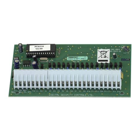
EHUOYAN YHY521X User manual

YHY521X
RFID
module
RFID/NFC Reader/Writer Module
User manual
Version 1.0
June, 2018
RFID
SMARTRFIDMODULE

EHUOYAN YHY521X
Manual
Page 2 of 36
CONTENT
1.Introduction......................................................................................................................................4
2.Gengral description..........................................................................................................................4
3.Features.............................................................................................................................................4
4.Application information ..................................................................................................................5
5.Quick reference data........................................................................................................................5
6.Ordering information ......................................................................................................................6
7.Block diagram...................................................................................................................................6
8.Pinning information.........................................................................................................................6
8.1.Pining...........................................................................................................................…….7
8.2.Pin description............................................................................................................…….7
9.Functional description.....................................................................................................................7
10.Digital interface..............................................................................................................................8
10.1.UART interface ........................................................................................................…….8
10.2.Selection of the transfer speeds...............................................................................…….8
10.3.Transfer protocol .....................................................................................................…….8
10.3.1.Host to YHY521X transfer protocol............................................................…….9
10.3.2. YHY521X to Host transfer protocol...........................................................…….9
11.Interrupt request system .............................................................................................................10
12.Antenna Power ...........................................................................................................................10
13.External antenna..........................................................................................................................10
14.YHY521X Command set .............................................................................................................11
14.1.Commands overview..............................................................................................…….11
14.2.Commands and response.......................................................................................…….12
14.2.1.Detect_Clone................................................................................................…….12
14.2.3.MConfigure..................................................................................................…….12
14.2.4.Download_Keys...........................................................................................…….16
14.2.7.Antenna_Control.........................................................................................…….17
14.2.8.Sense_mode..................................................................................................…….17
14.2.15.Card_Sleep.................................................................................................…….18
14.2.16.Card_Type .................................................................................................…….19
14.2.17.Card_ID......................................................................................................…….20
14.2.18.Block_Read................................................................................................…….20
14.2.19.Block_Write...............................................................................................…….21
14.2.20.Value_Init...................................................................................................…….22
14.2.21.Value_Read................................................................................................…….23
14.2.22. Value_Inc..................................................................................................…….24
14.2.23. Value_Dec .................................................................................................…….25
14.2.24. Value_Backup...........................................................................................…….26
14.2.25.Sector_Read...............................................................................................…….27
14.2.26.Sector_Write..............................................................................................…….28
14.2.27. Pages_Read_UL........................................................................................…….29
14.2.28. Pages_Write_UL.......................................................................................…….30
14.2.29. Ntag_Read_Text.......................................................................................…….30
14.2.30. Ntag_Write_Text......................................................................................…….31
14.2.31. Ntag_Read_URL......................................................................................…….32
14.2.32. Ntag_Write_URL.....................................................................................…….33

EHUOYAN YHY521X
Manual
Page 3 of 36
15.Electrial Characteristics..............................................................................................................34
15.1.Operating condition...............................................................................................…….34
15.2.Current consumption.............................................................................................…….35
16.Package outline.............................................................................................................................35
17.Contact information.....................................................................................................................36

EHUOYAN YHY521X
Manual
Page 4 of 36
1.Introduction
This document describes the functionality of the contactless reader/writer
YHY521X. It includes the functional and electrical specifications.
2. General description
The YHY521X is a highly integrated reader/writer for contactless
communication at 13.56MHz.The YHY521X reader supports ISO14443A/
MIFARE®mode.
The module provides a robust and efficient implementation of a demodulation
and decoding circuitry for signals from ISO/IEC 14443A/ MIFARE®
compatible cards and transponders. The digital part handles the complete
ISO/IEC 14443A framing and error detection(Parity & CRC).
In the master mode, YHY521X will seek the card or data itself and output to
host automatically.
In the slave mode, the module just needs only one command to perform one
action, such as read or write data from card’s block. The user does not need
input three steps : request, anticollision and selection. The module will do this
function for you automatically. What you need is just to send one command
to the module. Then it will send back what you want. Anything is just so
simple and so easy. Also, if there is any card goes into the RF field, the red
led on the module will light and the SIG pin will change from “1” to “0” to
indicate the event.
Host interface : Serial UART(RS232 TTL level).
3.Features
▲ Can detect UID clone card
▲ Small size and external antenna
▲Auto scan for presence of tags in and out and upload data
▲NFC NDEF text commands
▲Encrypted EEPROM to store up to 40 groups of keys
▲Contactless operating frequency 13.56 MHz
▲ Supports ISO14443A ,Mifare®Classic1K,Mifare®UltraLight, NTAG213
▲ RS232(TTL) Interface, baud rate up to 230400bps,default 19200bps
▲ Typical Operating Distance: 0 ~4cm
▲ Operating Voltage :DC 3.3V
▲ 1 LED indicator

EHUOYAN YHY521X
Manual
Page 5 of 36
▲ Size: 42mm ×26mm ×6mm
▲Weight:8g
4.Applicationinformation
YHY521X can be use on vending or game machine, secure access, parking,
payment, ticketing, leisure, member ship, time & attendance, biometrics, IT-access,
Identify, loyalty, Counter, data storage and fast data collection systems.
Figure 1. YHY521X Applications
5. Quick reference data _____________________________
Table 1: Quick reference data
Symbol Parameter Conditions Min Typ Max Unit
VCC Supply voltage GND=0V 2.7 3.3 3.6 V
IHPD Hard Power-down Current - - 10 uA
IASD Antenna Soft-down VCC =3.3V 15 20 mA
IVCC Supply Current VCC =3.3V 43 65 mA
DRW Read/Write card Distance VCC =3.3V 0 60 mm
Tamb Operating ambient temperature -25 +85 ℃
6.OrderingInformation
Table 2: Ordering Information

EHUOYAN YHY521X
Manual
Page 6 of 36
Model Number Name
YHY521X RFID module
7. Block diagram _ _____________________________
Figure 2. Simplified YHY521X Block diagram
The Analog circuitry and MFRC522 handle the modulation and demodulation
RFID signal.
The MCU handles the protocol requirements for the communication schemes
including the RF base protocols as well as the protocols for host
communication.
8. Pinning information _____________________________
8.1 Pining

EHUOYAN YHY521X
Manual
Page 7 of 36
Figure 3 – Pinning configuration
8.2 Pin description
Table 3: J1/2 Pin description
Pin Symbol Type Description
J1-1 GND PWR Power supply Ground
J1-2 VCC PWR Power supply, 3.3V DC
J1-3 TXD O Uart Transmitter
J1-4 RXD I Uart Receiver
J1-5 SIG O Interrupt output, LOW level indicates card in the field
J1-6 RFU O Reserved For Use
J4 used for connect to external antenna.
9. Functional description _____________________________
YHY521X supports the Reader/Writer mode for ISO/IEC 14443A/MIFARE card.
Figure 4 – YHY521X Reader/Writer mode

EHUOYAN YHY521X
Manual
Page 8 of 36
10. Digital interface ________ _____________________
10.1 UART Interface
Figure 5 – YHY521X UART interface to host
The YHY521X supports direct interfacing serial UART interface type(J1). It
is similar to RS232 with voltage levels according pad voltage supply.
10.2 Slection of the transfer speeds
The default transfer speed is 19200bps(19.2 k bit/s).
To change the transfer speed, the host controller has to write a value for the
new transfer speed by the CONFIG command, after reset the module, the
new speed will active.
Table 5: Selectable transfer speeds
Transfer Speed [kbit/s] Configure Code
2.4 1
4.8 2
9.6 3
14.4 4
19.2 5
38.4 6
57.6 7
115.2 8
230.4 9
10.3 Transfer Protocol
The original setting for the host and YHY521X communicates at 19200bps, N, 8, 1.
In the slave mode, the host first sends the command and the module executes the
operation and replies with a response to the command. The host can analyze the reply
to check if the operation was successful or if any error occurred during the operation.
10.3.1 Host to YHY521X Transfer Protocol
YHY521X
J1
RXD
TXD
SIG
HOST
TXD
RXD
INT1
Antenna

EHUOYAN YHY521X
Manual
Page 9 of 36
Table 5. UART frame send by host
1.
1. Header: This header has 2 bytes that indicates the beginning of a frame. These 2
bytes should be always 0xAA 0xBB.
2. Length: This byte is used to indicate the length of the payload data. This includes
the Length, Command and the Data bytes.
3. Command: This byte is used to instruct the module on what operation to perform.
4. Data: These are parameters for the module to execute the command. For example,
for a Read command, the data will be the block number to be read and the
authenticated key. For a Write command, this will be the block number and
the authenticated key and 16 bytes data to write into the block. For other
command, it maybe empty.
5. CSUM: This is the checksum byte. This byte is used on the host as well as the
module to check the validity of the packet and to trap any data
corruption. This is calculated by XOR all the bytes in the packet except
the Header and the CSUM byte.
CSUM=Length⊕Command⊕Data[0]⊕Data[1]…⊕Data[n-1]
Note: If there is one byte “0xAA” in the packet data from Length to CSUM,please
insert one byte “0x00” after “0xAA”,but the Length need not change.
Code example:
//--------------------------------------------------
if (cSendBuffer[i] == 0xAA)
{
TI = 0;
SBUF = 0;
while (!TI);
}
//--------------------------------------------------
10.3.2 YHY521X to Host Transfer Protocol
Table 6. UART frame send by YHY521X
1
.
1. Header: This header has 2 bytes that indicates the beginning of a frame. These 2
bytes should be always 0xAA 0xBB.
2. Length: This byte is used to indicate the length of the payload data. This includes
the Length, Command and the Data bytes
3. Status: This is the status for which the response is being sent back. If ok then the
module return the command which host has sent, if failure it return the
Header Length Command Data CSUM
2 Byte 1 Byte 1 Byte N Bytes 1 Byte
Header Length Status Data CSUM
2 Byte 1 Byte 1 Byte N Bytes 1 Byte

EHUOYAN YHY521X
Manual
Page 10 of 36
ones-complement code. For example, the command is 0x19, then the
ones-complement code is 0xe6.
4. Data: This contains the result data if an operation was successful. It may be empty.
5. CSUM: This is the checksum byte. This byte is used on the host as well as the
module to check the validity of the packet and to trap any data
corruption. This is calculated by XOR all the bytes in the packet except
the Header and CSUM byte.
CSUM=Length⊕Command⊕Response[0]⊕Response[1]⊕…⊕Response[n-1]
11. Interrupt Request System___ _____________________
The YHY521X indicates certain events by pin SIG. If activated, the signal on
pin SIG maybe used to interrupt the host using its interrupt handling
capabilities. This allows the implementation of efficient host software.
In the auto seek mode, if detect a card into the RF field, the SIG pin will
output “0”, else it will be “1”.
12. Antenna Power ___ _____________________
12.1 Antenna Power
You can send command Antenna-control to close the RF power and this will
save some power for the module. After switch off the antenna power, the
module will not read the RFID cards anymore until you send the command to
switch the antenna power on.
13. External antenna____________ _
The YHY521X module needs to connect to an external antenna to read and
write the RFID tags.
You can connect it to a PCB antenna or metal coil antenna. Big or small
antenna is ok if it can match the RF driver.
Figure 6 –external antenna

EHUOYAN YHY521X
Manual
Page 11 of 36
14. YHY521X Command Set ___ ____________________
14.1 Commands overview
The commands for the YHY521X include system commands and RFID
commands.
The system commands are used for controlling the module settings and
save parameters to the EEPROM.
The RFID commands are used to operate the RFID card, such as read or
write sector’s data.
Table 8: Command list
14.2 Commands and Response
After power on or reset YHY521X, the RED led will flash one time, it means
Code Command Description
SYSTEM COMMANDS
0x04 MConfigure Configure parameters to the module
0x05 Download_Keys Download auth keys to the module
0x11 Antenna_Control Control Antenna on or off
0x13 Sense_Mode Set Auto Sense Mode
RFID COMMANDS
0x12 Card_Sleep Card Sleep(Halt)
0x19 Card_Type Read Card Type
0x20 Card_ID Read Card UID
RFID M1 S50 commands
0x0c Detect_Clone Detect a clone card
0x21 Block_Read Read Data From Card Block, 16 bytes
0x22 Block_Write Write Data Into Card Block, 16 bytes
0x23 Value_Init Initialize block data to Value format, 4 bytes
0x24 Value_Read Read Value, 4 bytes
0x25 Value_Inc Increase Value, 4 bytes, Low Byte First
0x26 Value_Dec Decrease Value, 4 bytes, Low Byte First
0x27 Value_Backup Backup Value to Another Block
0x2a Sector_Read Read One Sector
0x2b Sector_Write Write One Sector
NFC NTAG213 commands
0x28 Pages_Read_UL Read out 4 pages of the UL data,
0x29 Page_Write_UL Write in 4 bytes data into 1 page to the UL chip
0x40 Ntag_Read_Text Read NFC text from NTAG chip
0x41 Ntag_Write_Text Write NFC text into NTAG chip
0x42 Ntag_Read_URL Read NFC URL from NTAG chip
0x43 Ntag_Write_URL Write NFC URL into NTAG chip

EHUOYAN YHY521X
Manual
Page 12 of 36
that YHY521X is ready.
If a Mifare®tag detected by the module, pin SIG will change from “1” to “0”
and the red led on board will light till the tag moves out of RF field.
The RED led will flash during data stream exchanging between host and
YHY521X.
14.2.1 Detect_Clone
This command will detect the UID clone card, if it is a clone card, it will
reply success, else reply failure.
Table 9. Command--:Host
Æ
YHY521X
Send Header Length Command Data XOR Checksum
0xAA 0xBB 0x02 0x0c BCC
Table 10. Response--: YHY521X
Æ
Host
Receive Head Length Status Data XOR Checksum
Success 0xAA 0xBB 0x02 0x0C 0x0E
Failure 0xAA 0xBB 0x02 0XF3 0Xf1
Table 11 Example
Send AA BB 02 0C
0
E
Description
AA BB
02
0C
0E
Head
Length
COMMAND
BCC=02
⊕
0C
Receive(Success) AA BB 02 0C 0E
Description
AA BB
02
0C
0E
Head
Length
Status
BCC
Receive(Failure) AA BB 02 F3 FE
Description
AA BB
02
F3
F1
Head
Length
Error
BCC
14.2.3 MConfigure
This command will configure parameters to the YHY521X. After Reset
YHY521X the configuration will active.
Table 15. Command--:Host
Æ
YHY521X
Send Header Length Command Data XOR Checksum
0xAA 0xBB 0x12 0x04
Configure data:
16 bytes BCC
Configure data: 16 bytes.
Table 16. Configure data

EHUOYAN YHY521X
Manual
Page 13 of 36
D[0] D[1] D[2..7] D[8] D[9] D[10] D[11] D[12] D[13] D[14] D[15]
Auto
code Key
Type Key
String Block
R AddrL RFU Start
Sector RFU Auth
Mode RFU Baud
Code
D[0]:Auto code -----
0—Auto function off ,the YHY521X will not auto seek card and the SIG pin is not active.
1—Auto seek card, if there are cards in the RF field, the RED led will light and SIG pin will
output low level.
2—Same 1, and it will read the card id and upload to host, and then halt the card.
3—Same 1, and it will read the selected block and upload to host, and then halt the card.
7-- Same 1, and it will read the selected sector and upload to host, and then halt the card.
8-- Same 1, and it will read the NTAG213 NDEF text and upload to host, and then halt the
card.
9—Same 1, and it will read the card id when the tag in and out and upload to host, and then
halt the card.
D[1]:Key Type -----
0x00 ---Key A
0x01 ---Key B
D[2..7]:Key string -----
Key(6 Bytes) to authenticate the mifare card
D[8]:Block R -----
Define one block of the card to be read.
D[9]: AddrL--- Node address for mode 9.
D[10]:RFU-default 0x00
D[11]:Sector to be scan
D[12]:RFU-default 0x00
D[13]:Auth mode -----
Define the auth mode----
0—Auth directly from host, default mode
1—The YHY521X will use the downloaded keys for authentication card
D[14]:RFU -----
Reserved For future Used. Default 0x60.
D[15]:Baud code -----
See table 5 for the baud rate code.

EHUOYAN YHY521X
Manual
Page 14 of 36
Table 17. Response--: YHY521X
Æ
Host
Receive Head Length Status Data XOR Checksum
Success 0xAA 0xBB 0x02 0x04 0x06
Failure 0xAA 0xBB 0x02 0xFB 0xF9
Table 18. Example 1 ---Auto read card id, Auto code=0x02
Send AA BB 12 04
0
2
0
0
F
F FF FF FF FF FF 00
0
0
00 00 00 00
00
08
1C
Description
AA BB
12
04
02
00..00
08
1C
Head
Length
COMMAND
Auto code—auto read id
Any data
Baud code---115200bps
BCC
Receive(Success) AA BB 02 04 06
Description
AA BB
02
04
06
Head
Length
Status
BCC
Receive(Failure) AA BB 02 FB F9
Description
AA BB
02
FC
FE
Head
Length
Error
BCC
If success then reset the YHY521X to active this function. The reader will read the card id
itself when there is a card into the RF field and then output the id to host, at the same time
the buzzer would beep one time if it is connecting to a buzzer.
Example 2 ---Auto read card block, Auto code=0x03
Configure command--: Host
Æ
YHY521X
AA BB 12 04 03 00 FF FF FF FF FF FF 00 05 06 03 04 01 60 08 78
Description:
03:Auto code
00 FF FF FF FF FF FF: Auth key A and key string
00: Read block 0
01: Auth mode 1
08: Baud code,115200bps
If success then reset the YHY521X to active this function. The reader will read the card
block itself when there is a card into the RF field and then output the block data to host, at
the same time the buzzer would beep one time if it is connecting to a buzzer. Below is the
output string example.
YHY521X
Æ
Host----
AA BB 12 51 5E C0 E0 7A 04 88 04 00 47 51 35 56 61 10 28 08 EB
Description:

EHUOYAN YHY521X
Manual
Page 15 of 36
51:Status code
5E C0 E0 7A 04 88 04 00 47 51 35 56 61 10 28 08: Data in the block 0
Example 3 ---Auto Read NTAG213 NFC NDEF text dada, Auto code=0x08
Configure command--: Host
Æ
YHY521X
AA BB 12 04 08 00 FF FF FF FF FF FF 00 00 00 00 00 00 00 05 1B
Description:
08:Auto code
05: Baud code,19200bps
If success then reset the YHY521X to active this function. The reader will read the NFC tag
when there is a tag into the RF field and then output the status to host. Below is the output
string.
AA BB 1E 40 31 53 69 6E 67 6C 65 4C 69 6E 65 31 32 33 34 35 36 37 38 39 FE 04 A7 B3
02 09 40 80 6F
Description:
40:Status code
31 53 69 6E 67 6C 65 4C 69 6E 65 31 32 33 34 35 36 37 38 39
:
Ascii code of the
“1SingleLine123456789”
FE: End of this text
04 A7 B3 02 09 40 80
:
UID of this tag
Auto scan commands:
AA BB 12 04 01 00 FF FF FF FF FF FF 00 00 00 00 00 00 00 05 12// Auto mode 1,baud 19200
AA BB 12 04 02 00 FF FF FF FF FF FF 00 00 00 00 00 00 00 05 11// Auto mode 2, scan UID
AA BB 12 04 02 00 FF FF FF FF FF FF 00 00 00 00 00 00 00 03 17 // Scan UID, baud 9600
AA BB 12 04 03 00 FF FF FF FF FF FF 00 00 00 00 00 00 00 05 10//Auto mode 3, scan block
AA BB 12 04 07 00 FF FF FF FF FF FF 00 00 00 01 00 00 00 05 15// Auto mode 7, scan sector1
---------------------------------------------------------------------------------------------------------------
AA BB 12 04 08 00 FF FF FF FF FF FF 00 00 00 00 00 00 00 05 1B// Auto mode 8, NFC scan
Scan data example:
, get nfc text (1SingleLine123456789):
AA BB 1E 40 31 53 69 6E 67 6C 65 4C 69 6E 65 31 32 33 34 35 36 37 38 39 FE 04 A7 B3 02 09 40
80 6F
--------
:
40
:
Status code
31 53 69 6E 67 6C 65 4C 69 6E 65 31 32 33 34 35 36 37 38 39
:
NFC text (1SingleLine123456789)
ascii code
FE:NFC end code
04 A7 B3 02 09 40 80
:
UID
-------------------------------------------------------------------------------------------------------
AA BB 12 04 09 00 FF FF FF FF FF FF 00 02 00 00 00 00 00 05 18 // Auto mode 9,
----------------mode: 9, node address: 02, baud:19200.
Scan data example:

EHUOYAN YHY521X
Manual
Page 16 of 36
AA BB 08 60 02 01 40 9C 48 61 9E , ‘01’:Enter RF field, node: 02, UID: 40 9C 48 61;
AA BB 08 60 02 00 40 9C 48 61 9F , ‘00’:Left RF field, node: 02, UID: 40 9C 48 61;
AA BB 0B 60 02 01 04 A7 B3 02 09 40 80 B3 , ‘01’:Enter RF field, node: 02, UID: 04 A7 B3 02
09 40 80;
AA BB 0B 60 02 00 04 A7 B3 02 09 40 80 B2, ‘00’:Left RF field, node: 02, UID: 04 A7 B3 02 09
40 80;
---------------------------------------------------------------------------------------------------------------------
14.2.4 Download_Keys
This command can load up to 40 groups keys to the YHY521X’s EEPROM, all
the data stored in the EEPROM is encrypted. When auth mode is 1, the reader
will use the EEPROM’s key to auth the card. After reset this keys will active.
Table 19. Command--: Host
Æ
YHY521X
Send Header Length Command Data XOR Checksum
0xAA 0xBB 0x09 0x05
7 bytes
Sector: 1 byte
Keys: 6 bytes BCC
Sector: 0—0x27 (mifare 4 k card has 40 sectors)
Keys: KeyA or KeyB, default FF FF FF FF FF FF.
Table 20. Response--: YHY521X
Æ
Host
Receive Head Length Status Data XOR Checksum
Success 0xAA 0xBB 0x02 0x05 0x07
Failure 0xAA 0xBB 0x02 0xFA 0xF8
Table 21. Example
Send AA BB 09 05 01 FF FF FF FF FF FF 0D
Description
AA BB
09
05
01
FF FF FF FF FF FF
0D
Head
Length
COMMAND
Sector 01
Key
BCC
Receive(Success) AA BB 02 03 01
Description
AA BB
02
05
07
Head
Length
Status
BCC
Receive(Failure) AA BB 02 FC FE
Description AA BB
02
FA
Head
Length
Error

EHUOYAN YHY521X
Manual
Page 17 of 36
F8 BCC
14.2.7 Antenna_Control
This command set the antenna power on or off .
Table 28. Command--:Host
Æ
YHY521X
Send Header Length Command Data XOR Checksum
0xAA 0xBB 0x03 0x11 Switch:1Byte BCC
Switch----
0x00: antenna soft power-down
0x03: antenna soft power-on
Table 29. Response--: YHY521X
Æ
Host
Receive Head Length Status Data XOR Checksum
Success 0xAA 0xBB 0x02 0x11 0x13
Failure 0xAA 0xBB 0x02 0xEE 0xEC
Table 30. Example
Send AA BB 03 11 00 12
Description
AA BB
03
11
00
12
Head
Length
COMMAND
antenna soft power-down
BCC
Receive(Success) AA BB 02 11 13
Description
AA BB
02
11
13
Head
Length
Status
BCC
Receive(Failure) AA BB 02 EE EC
Description
AA BB
02
EE
EC
Head
Length
Error
BCC
14.2.8 Sense_Mode
This command can change the auto sense mode any time during the YHY521X
working, it needs no reset operation.
Table 31. Command--:Host
Æ
YHY521X
Send Header Length Command Data XOR Checksum
0xAA 0xBB 0x03 0x13 Auto code:1Byte BCC
Auto code -----
0—Auto function off ,the YHY521X will not auto seek card and the SIG pin is not active.
1—Auto seek card, if there are cards the RED led will light and SIG pin output low level.
2—Same 1, and it will read the card id and upload to host, and then halt the card.

EHUOYAN YHY521X
Manual
Page 18 of 36
3—Same 1, and it will read the selected block and upload to host, and then halt the card.
Table 32. Response--: YHY521X
Æ
Host
Receive Head Length Status Data XOR Checksum
Success 0xAA 0xBB 0x02 0x13 0x11
Failure 0xAA 0xBB 0x02 0xEC 0xEE
Table 33. Example
Send AA BB 03 13 00
10
Description
AA BB
03
13
00
10
Head
Length
COMMAND
Auto off
BCC
Receive(Success) AA BB 02 13 11
Description
AA BB
02
13
11
Head
Length
Status
BCC
Receive(Failure) AA BB 02 EC EE
Description
AA BB
02
EC
EE
Head
Length
Error
BCC
14.2.15 Card_Sleep
This command sets the Card into sleeping. After successfully operation
the card will be halt. Reactivate the card need to remove the card from
antenna area and put the card into antenna area again. Or reset the
YHY521X to repower the card.
Table 51. Command--:Host
Æ
YHY521X
Send Header Length Command Data XOR Checksum
0xAA 0xBB 0x02 0x12 0x10
Table 52. Response--: YHY521X
Æ
Host
Receive Head Length Status Data XOR Checksum
Success 0xAA 0xBB 0x02 0x12 0x10
Failure 0xAA 0xBB 0x02 0x ED 0xEF
Table 53. Example
Send AA BB 02 12
10
Description
AA BB
02
12
10
Head
Length
COMMAND
BCC
Receive(Success) AA BB 02 12
10

EHUOYAN YHY521X
Manual
Page 19 of 36
Description
AA BB
02
12
10
Head
Length
Status
BCC
Receive(Failure) AA BB 02 ED EF
Description
AA BB
02
ED
EF
Head
Length
Error
BCC
14.2.16 Card_Type
This command reads card type.
Table 54. Command--:Host
Æ
YHY521X
Send Header Length Command Data XOR Checksum
0xAA 0xBB 0x02 0x19 0x1B
Table 55. Response--: YHY521X
Æ
Host
Receive Head Length Status Data XOR Checksum
Success 0xAA 0xBB 0x04 0x19 Card type:
2Bytes BCC
Failure 0xAA 0xBB 0x02 0x E6 0xE4
Card type:
0x0400---Mifare 1k card(s50)
0x0200---Mifare 4k card(s70)
0x4400---UL(NTAG2XX)
Table 56. Example
Send AA BB 02 19
1
B
Description
AA BB
02
19
1B
Head
Length
COMMAND
BCC
Receive(Success) AA BB 04 19 04 00
19
Description
AA BB
04
19
04 00
19
Head
Length
Status
Card TYPE 04 00: S50 Card; 02 00: S70 Card
BCC
Receive(Failure) AA BB 02 E6 E4
Description
AA BB
02
E6
E4
Head
Length
Error
BCC
14.2.17 Card_ID
This command read the mifare card UID.

EHUOYAN YHY521X
Manual
Page 20 of 36
Table 57. Command--:Host
Æ
YHY521X
Send Header Length Command Data XOR Checksum
0xAA 0xBB 0x02 0x20 0x22
Table 58. Response--: YHY521X
Æ
Host
Receive Head Length Status Data XOR Checksum
Success 0xAA 0xBB 0x06 0x20 Card ID: 4Bytes BCC
Failure 0xAA 0xBB 0x02 0x DF 0xDD
Table 59. Example
Send AA BB 02 20
22
Description
AA BB
02
20
22
Head
Length
COMMAND
BCC
Receive(Success) AA BB 06 20
9
2 BF 72 5
9
20
Description
AA BB
06
20
92 BF 72 59
20
Head
Length
Status
Card ID
BCC
Receive(Failure) AA BB 02 DF DD
Description
AA BB
02
DF
DD
Head
Length
Error
BCC
14.2.18 Block_Read
This command reads data from the appointed block. One block has 16
bytes.
Table 60. Command--:Host
Æ
YHY521X
Send Header Length Command Data XOR Checksum
0xAA 0xBB 0x0A 0x21
Block Info:
8 bytes BCC
Block Info: Key type +Block number + Key
Key type: 1 byte, 0x00—Key A, 0x01—Key B.
Block number: 1 byte, 0x00..0xff (0..255) (*)
Key: 6 bytes, default “FFFFFFFFFFFF”
(*)Note: If auth mode is “1”, then this key is not active, it can be any 6 data bytes.
Table 61. Response--: YHY521X
Æ
Host
Receive Head Length Status Data XOR Checksum
Success 0xAA 0xBB 0x12 0x21 Block data:
16Bytes BCC
Failure 0xAA 0xBB 0x02 0x DE 0xDC
Table of contents
Popular Control Unit manuals by other brands
Sensity Systems
Sensity Systems NetSense LSNM-0001-A reference guide
Balluff
Balluff BNI ECT-507-005-Z040 user guide
Leadshine
Leadshine 2CS3EIP Series user manual
schmersal
schmersal SRB-E-301MC operating instructions

Dynamic Engineering
Dynamic Engineering PMC-UNIV-TEST user manual

Symmons
Symmons Temptrol II Installation, operation & service instructions
