PK-A3258-10-00-0A© 2018 Leviton Mfg. Co., Inc. For Technical Assistance Call: 1-800-824-3005 (U.S.A. Only) www.leviton.com
LIMITED 1 YEAR WARRANTY AND EXCLUSIONS
Leviton warrants to the original consumer purchaser and not for the benefit of anyone else that this product at the time of its sale by Leviton is free of defects in materials and workmanship under normal and proper use for one year from the purchase
date. Leviton’s only obligation is to correct such defects by repair or replacement, at its option. For details visit www.leviton.com or call 1-800-824-3005. This warranty excludes and there is disclaimed liability for labor for removal of this product
or reinstallation. This warranty is void if this product is installed improperly or in an improper environment, overloaded, misused, opened, abused, or altered in any manner, or is not used under normal operating conditions or not in accordance
with any labels or instructions. There are no other or implied warranties of any kind, including merchantability and fitness for a particular purpose, but if any implied warranty is required by the applicable jurisdiction, the duration of
any such implied warranty, including merchantability and fitness for a particular purpose, is limited to one year. Leviton is not liable for incidental, indirect, special, or consequential damages, including without limitation, damage to,
or loss of use of, any equipment, lost sales or profits or delay or failure to perform this warranty obligation. The remedies provided herein are the exclusive remedies under this warranty, whether based on contract, tort or otherwise.
FOR CANADA ONLY
For warranty information and/or product returns, residents of Canada should contact Leviton in writing at Leviton Manufacturing of Canada Ltd to the attention of the Quality Assurance Department,
165 Hymus Blvd, Pointe-Claire (Quebec), Canada H9R 1E9 or by telephone at 1 800 405-5320.
INDUSTRY CANADA COMPLIANCE STATEMENT:
This device complies with Industry Canada license-exempt RSS standard(s). Operation is subject to the following two conditions: (1) this device may not cause interference, and (2) this device must accept any interference, including
interference that may cause undesired operation of the device. IMPORTANT! Any changes or modifications not expressly approved by the party responsible for compliance could void the user’s authority to operate this equipment. This
Class A digital apparatus complies with Canadian CAN ICES-3(A)/NMB-3(A).
TRADEMARK DISCLAIMER: Use herein of third party trademarks, service marks, trade names, brand names and/or product names are for informational purposes only, are/may be the trademarks of their respective owners; such use is
QRWPHDQWWRLPSO\DI¿OLDWLRQVSRQVRUVKLSRUHQGRUVHPHQW
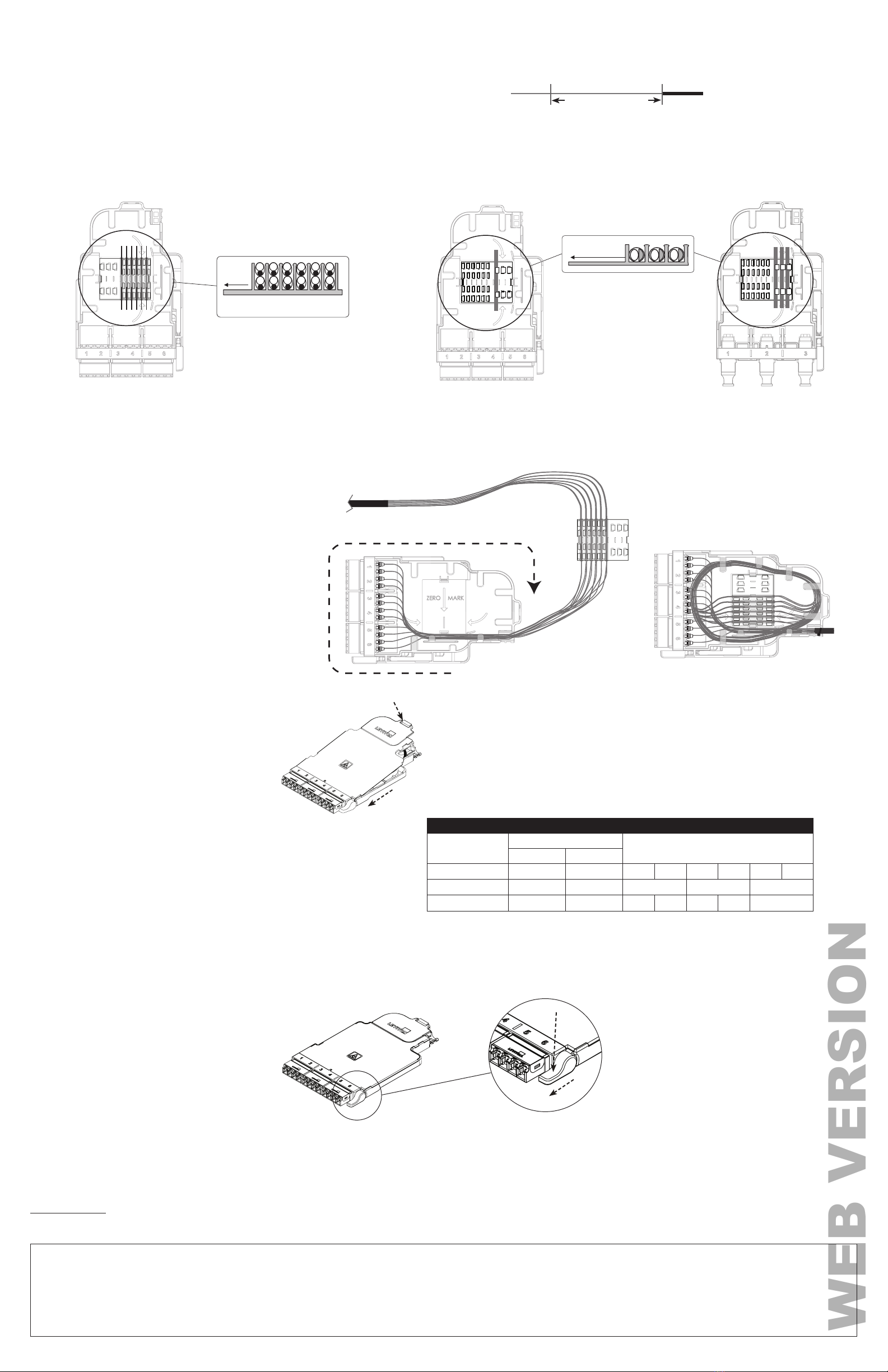
7. Terminate.
NOTE: Cleave lengths and termination steps can vary. Consult your splicer instructions.
a. Install splice sleeves
b. Shorten each fiber to 35 mm past Zero Mark using guide.
c. Strip.
d. Perform fusion splicing per manufacturer's instructions
e. Place fibers in splice sleeve holder after termination as shown by termination type.
8. Route assembly into module (single fiber or mass fusion).
a. Feed fibers through channel shown.
b. Rotate module base clockwise as you place fibers under tabs.
c. Position sleeve holder and snap into place, positioning
the last 250 um of fiber under the LC connectors
d. Continue rotating module clockwise, routing
trunk fibers under tabs as you go, with final length
of fiber in outermost channel.
e. Secure trunk jacket at entrance, tie with wraps.
11. Mount module in enclosure.
All modules install through front of enclosure. If using an enclosure or HDX patch
deck with sliding trays, individual trays can be removed for ease of use.
a. Place module in guide rails of enclosure.
b. Slide module toward back of enclosure until latch engages.
12. To remove module.
a. Gently press button.
b. Remove module.
Label Printing Organization by Fiber Adapter Type
HDX
Splice Module
Per Column
Number Scheme
Port Spacing No. of Ports
Quad LC (duplexed) 0.6 6 1 2 3 4 5 6
Quad LC (by fiber) 0.6 12 1-2/3-4 5-6/7-8 9-10/11-12
MTP (3 port) 1.20 3 1 Space 2 Space 3
9. Replace lid.
NOTE: To avoid damaging fibers, verify all
fiber optic cabling is correctly routed within the
module base under the cable management tabs
prior to installing and securing the lid.
2
1
10. Label module.
Affix labels as shown.
NOTE: Make sure the label surface area is free of dirt, oil and debris.
When wiping down surface area, use isopropyl alcohol or a simple soap
and water solution.
a.
b.
PLACE FIBER
HERE TO MARK
end of stripped
fiber 35mm
end of buffered fiber
(zero mark)
REMOVE ACRYLATE
TRUNK
LEGS
PIGTAILS
1234 5678 9101112
TRUNK
LEGS
PIGTAILS
123
SINGLE SPLICE
HOLDERS NOT USED
RIBBON SPLICING
TRUNK
LEGS
PIGTAILS
1 2 3 4 5 6 7 8 9 10 11 12
TOP ROW – EVEN FIBERS
BOTTOM ROW – ODD FIBERS
RIBBON
HOLDERS
NOT USED 1
24
35
68
7
10
9
12
11
SINGLE SPLICING
SIDE VIEW
Splice Sleeve Holder with
Spliced Fiber (in 40 mm sleeve)
SIDE VIEW
Splice Sleeve Holder with Ribbon Splicing
Single Fusion Splicing for LC pigtails Mass Fusion Splicing for LC pigtails Mass Fusion Splicing for MTP pigtails
PIGTAILS
1234 5678 9101112
1 2 3 4 5 6 7 8 9 10 11 12


