Eicom HTEC-500 User manual

HPLC-ECD Stand Alone System
(HTEC-500)
User’s Guide
Eicom Corporation
AC01-0319

Contents
1. Important Checklist Before Operation ............................................. 1
2. Terminology .......................................................................................... 2
3. A List of Fitting Parts and Directions for Use...................................... 3
4. Mobile Phase Preparation.................................................................. 4
5. System Installation ............................................................................... 5
5-1. Wiring.......................................................................................... 5
5-2. Tubing and Degasser............................................................... 5
5-3. Connecting to the Autoinjector and the Autosampler
(Plumbing) ......................................................................................... 5
5-4. Connecting to the Autoinjector and the Autosampler
(Electrical Signal Connection) ....................................................... 6
6. Online Elution Degassing System ...................................................... 7
6-1. If you think the degassing efficiency is reduced,
you may diagnose the problem by the
following procedure: .................................................... 7
7. HPLC Pump Operation ....................................................................... 8
7-1. Run/Stop .................................................................................... 9
7-2. Flow Rate Setting...................................................................... 9
7-3. Pulse Free Mode Setting.......................................................... 10
7-4. Function of Pulse Free Mode .................................................. 10
8. How to Fix Pump Errors and Problems .............................................. 11
8-1. Less Flow Rate, Less Pump Pressure or
Unstable Pump Pressure ............................................... 11
8-2. Types of Pump Errors ................................................................ 12
8-3. How to Fix these Errors.............................................................. 13

9. Manual Sample Injector and Autoinjector...................................... 16
9-1. Structure..................................................................................... 16
9-2. Operation of Manual Injector ................................................ 16
9-3. Autosampler and Autoinjector Setup ................................... 17
10. Precolumn ............................................................................................ 18
10-1. Types of Precolumn Housing and Line Filters........................ 18
10-2. Identification of Precolumn Quality....................................... 19
10-3. How to Repack ......................................................................... 20
10-4. Filter Exchange ......................................................................... 21
11. ECD Operation..................................................................................... 22
11-1. Basics.......................................................................................... 22
11-2. Working Electrode.................................................................... 23
11-3. Applied Potential...................................................................... 23
11-4. Time Constant ........................................................................... 25
11-5. Background Current ................................................................ 25
11-6. If Background Current is High ................................................. 25
11-7. Caution for the Platinum Working Electrode........................ 25
12. Storage of the System......................................................................... 26
12-1. Short-term (A few days to a few weeks) ................................................26
12-2. Long-term (more than a few days or a few weeks) ............................26
13. Storage of a Standard Sample ......................................................... 27
14. Regular Maintenance Schedule....................................................... 28
Daily Maintenance.............................................................................. 28
Occasional Maintenance.................................................................. 28
Yearly Maintenance ........................................................................... 28
15. Troubleshooting ................................................................................... 30
Appendix. A ................................................................................................... 33

This page intentionally left blank.
1
HTEC-500
1. Important Checklist Before Operation
• The separation column and the enzyme column must be held firmly by the column clip. The stainless
steel surfaces should make good contact with each other in order to ground static electricity. This
may be the cause of noise in the ECD.
• Place the mobile phase container and the waste container on the same level as the HTEC-500.
• Use glass bottles as mobile phase and ultrapure water containers. Do not use any plastic containers.
• Rinse behind the pump pistons with ultrapure water before and after use through the pump piston
washing port. Do not use any organic solvents in the rinse solution. If precipitation or something blocks
the line, do not push out with high pressure or force. First, disconnect the line and then remove the
source of the blocking.
• Before opening the detector cell for maintenance, remove the outlet screw and aspirate all the
remaining mobile phase in the detector cell with a syringe.
• Pay attention to prevent any tubing from becoming blocked. Salt solvents must be rinsed out by
ultrapure water before an organic solvent of a high concentration is used. Drying out of the salt
solvent should also be avoided.
• Pay attention not to allow any leakage from any connection points of the tubing. Leakage is not only
harmful for the equipment but also generates pump pulse noise.
• When air is thought to be present in the tubing or the pump, please purge the air (see chapter 8,
page 11). Then you can connect a column.
• Pulse free mode must be switched on during the analysis.
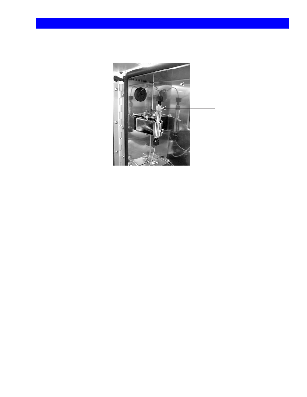
Column Clip
Separation Column (PP-ODS)
Door
A separation column must be held firmly by the column clip.
When an enzyme column is used, the enzyme column must
also be held firmly by the column clip. The respective stainless
steel surfaces should make good contact in order to ground
static electricity. This can be the cause of noise in the ECD.
Fig. 1 Separation Column Installation
2
HTEC-500
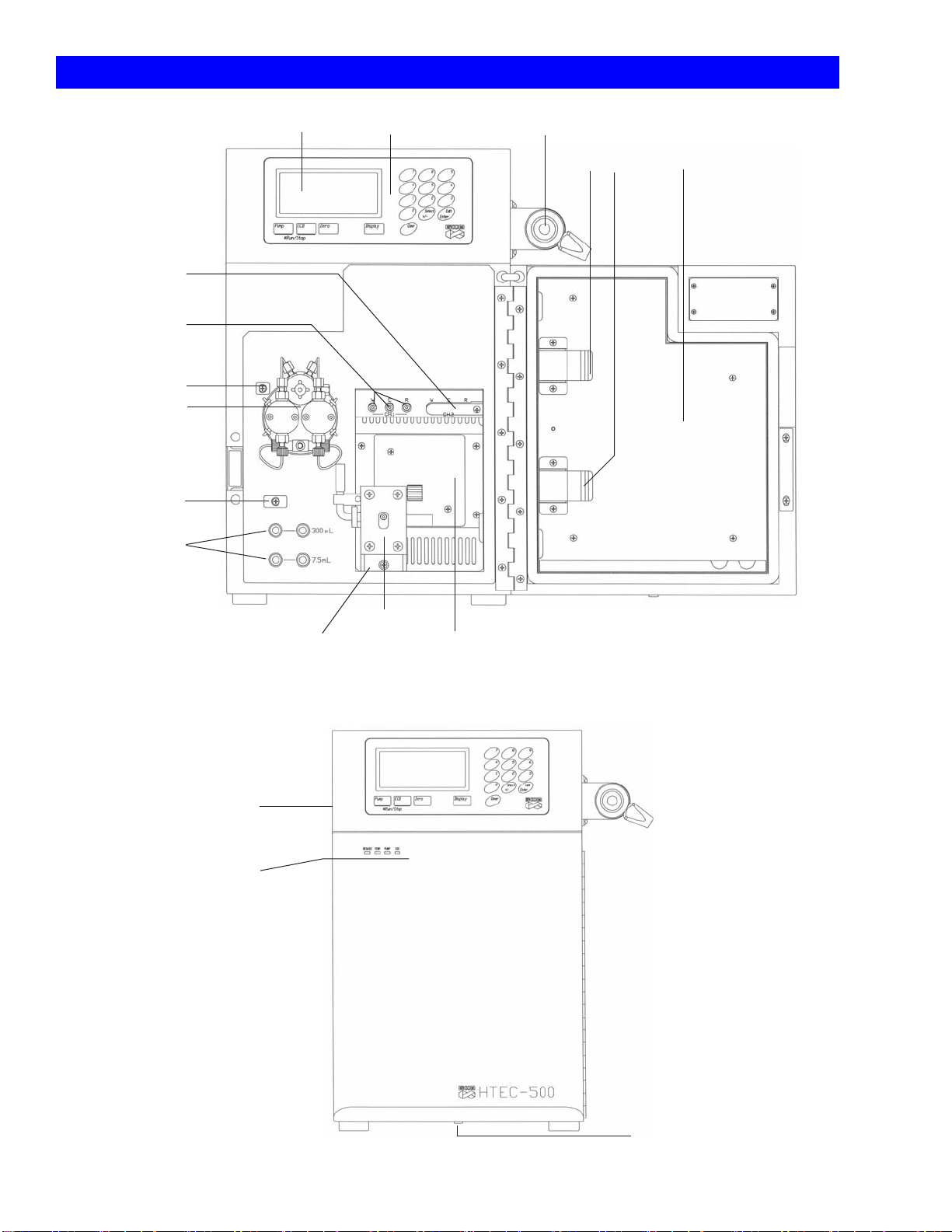
2. Terminology
Display Manual Injector
HPLC Pump
(See Fig. 7)
Online Elution
Degasser
Column Clips
ECD Cell
Door Cabinet
Thermo Controller
Control Panel
ECD Terminal Ch1
Tubing Guide
Terminal Ch2
(for PEC-510)
Tubing Guide
Cell Mount
Fig. 2 HTEC-500 Front View (Door open)
Status Indicator
Cabinet Drain
Main Power Switch
(Back Side)
Fig. 3 HTEC-500 Front View (Door closed)
3
HTEC-500
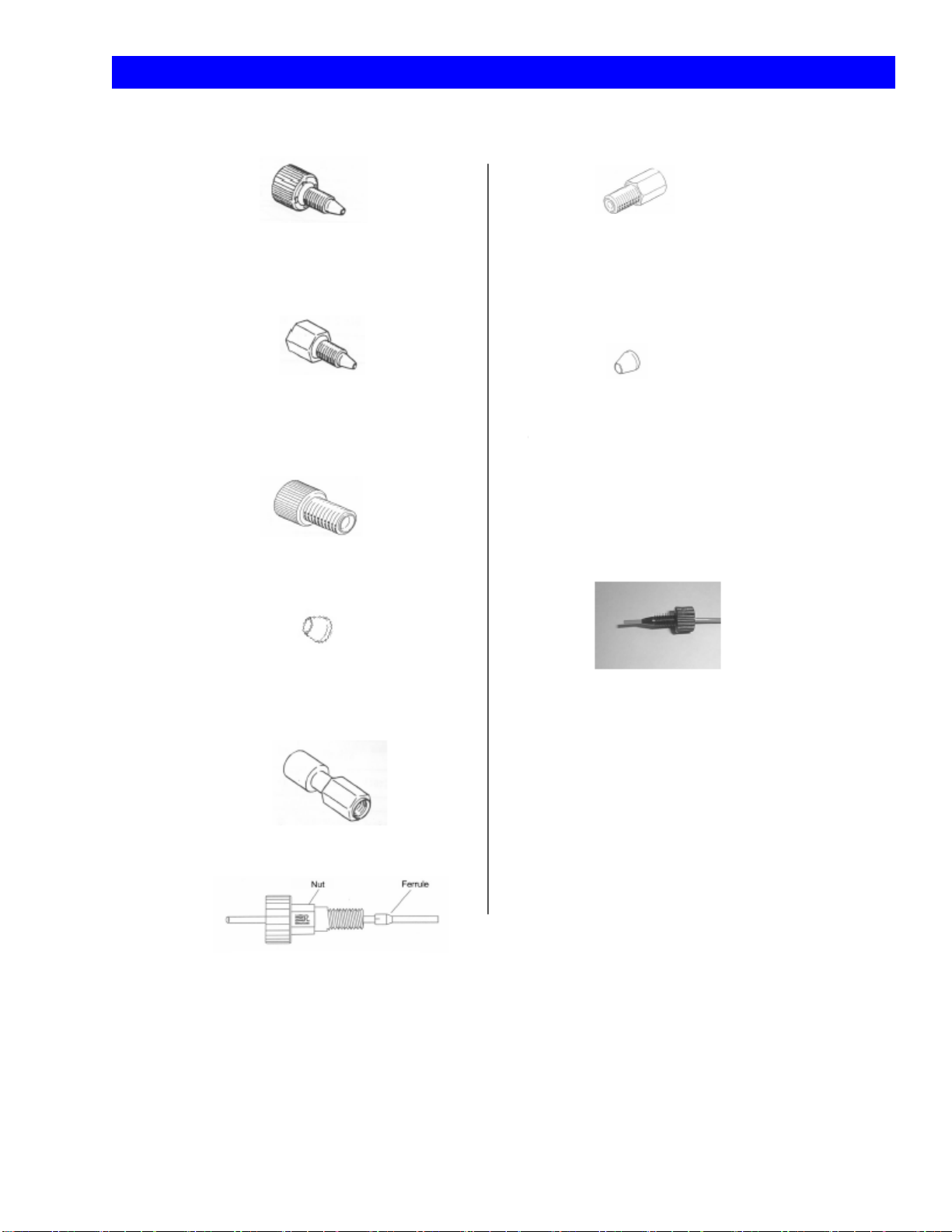
3. A List of Fitting Parts and Directions for Use
Tough Connector
Low pressure part. For column connections.
Flat Seal for Degasser
The wide side is for the degasser and
narrow side is for the nut.
Hex Nut
High pressure part (pumps)
Rheodyne PEEK nut
Pheodyne PEEK Ferrule
(For Injector)
Nut for Inlet of Cell
Ferrule for Inlet of Cell
The narrow side is for the cell and
the wide side is for the nut.
Flat Seal Nut
Two-way Joint
Tubing connection
Connect the tubing and keep its tip sticking out of the ferrule
(as seen above), except for the connection with the degasser
which uses a flat seal. First, put the tubing through the ferrule
and put its tip into the holder. Then connect it by tightening
the screw. The connecting part should be sealed by a cross
section of the tubing and the holder of the tubing. For the
injector connection, use the nuts and ferrules for its connection
only. The slit side is for the nut (see figure).
Fig. 4 Tubing Connection Parts and Directions for Use

4
HTEC-500
4. Mobile Phase Preparation
Prepare the mobile phase according to the Eicom technical information. The mobile phase preparation
depends on what you are measuring with the HTEC-500. Please read below to find a general method
for mobile phase preparation. Also, the following points should be noted because the ECD has a higher
sensitivity compared to other detectors:
• Use ultrapure water (the resistance of the water needs to be at least 18.2 mega-ohm/cm). Any
solvent, such as mobile phase, or water applied to this system should be stored in a glass bottle.
• Use glass instruments for the preparation of mobile phase. Before use, these instruments should be
rinsed out by water and then by ultrapure water.
• Use reagents of super grade or HPLC grade quality. The following are our recommendations: for
sodium 1-Octanesulfonate, use Nacalai (code 3179-62, available at Eicom); for sodium
1-Decanesulfonate, use TCI (code I-0348 available at VWR); and for EDTA-2Na use Dojindo
(code 372.24). Separation patterns or ECD can be influenced by the use of other reagents.
• Methanol and buffer solution/water must be measured separately and then mixed. Otherwise the
methanol concentration will be higher than the designated level due to the solubility of methanol in
water.
• Do not use a sonicator for dissolving salts in the mobile phase. This may raise the background current
of the ECD.
• When all reagents are added, plug the bottle and shake and mix it thoroughly. Check if all reagents
are dissolved.
• Filtration is good for removing unwanted particles but can be a source of chemical contamination.
We do NOT recommend you to filter the mobile phase but rather encourage you to avoid any
contamination during the preparation of the mobile phase. Using less glassware and always putting a
cap or cover on the top of the containers helps to reduce chances of contamination. If you must filter
the mobile phase, use a chemically clean apparatus and do not store the mobile phase in plastic
bottles after the filtration.
• A filter at the end of the inlet tubing placed in the mobile phase can also be a cause of chemical
contamination or bacterial growth. Eicom does not recommend you to use these type of filters. If you
need to use one, please replace the filter frequently and keep it clean. Instead of these filters, we
recommend you to set a precolumn before the separation column. (If using the PP-ODS column,
please use in-line filter #PP-LF, before the precolumn and put a precolumn before the injectors.) The
precolumn filter after the HPLC pump does not prevent contamination of the HPLC pump.
• Mobile phase can only be used for one week from the date of opening/preparation. Bottles should
be well sealed while it is being used for HPLC. Do not add new mobile phase to the bottle of old
mobile phase. This is to avoid the breeding of various germs in the system.

5
HTEC-500
5. System Installation
5-1. Wiring
Connect the terminal adapter (orange color) to the terminal at the right side of the system. Then
connect the AC cable to the main power supply and turn on the system. “Initializing” appears on the
display, followed by the ECD controller screen. Now you can turn off the system for the next steps
described below.
5-2. Tubing and Degasser
Pull the tubing’s for the pump rinse, the mobile phase suction and the cell drain out of the HTEC-500
system. Put all the equipment on a level place. Mobile phase and waste bottles should be placed on
the same level as the HTEC-500 (See Fig. 5).
5-3. Connecting to the Autoinjector and the Autosampler (Plumbing)
Injectors of the autoinjector (online autoinjector, EAS-20) and/or the autosampler should be set up
downstream to the manual injector. For the autoinjector, connect no. 3 port of the manual injector with
no. 2 port of the autoinjector using 0.125 mm PEEK tubing (red). Then connect no. 3 port of the
autoinjector with the separation column using the same kind of tubing. For the autosampler (model
Alcott 719D or 719AL), connect no. 3 port of the manual injector with no. 2 port of the autoinjector and
no. 3 port of the autoinjector with the separation column.
Please place the HTEC-500 on a horizontal and stable table. The mobile
phase and waste containers should be placed on the same level as the
HTEC-500.
Fig. 5 HTEC-500 Installation
HTEC-500
Mobile Phase
(Always use a glass bottle)
Pump Piston Washing
Syringe for Aspiration
Pump Piston Washing
Ultrapure Water
Mobile Phase Waste
Injector Waste

6
HTEC-500
5-4. Connecting to the Autoinjector and the Autosampler
(Electrical Signal Connection)
A trigger signal needs to be sent from the online autoinjector or the autosampler to the data acquisition
unit to inform it of the injection timing. It also needs to be sent to the HTEC-500 in order to give the auto
zero signal. The auto zero works to shift the baseline to the zero level. Please connect the trigger signal
output on the autoinjector/autosampler with “signal in” of the terminal adapter located on the left side
of the HTEC-500. Please also refer to Fig. 6. There is no polarity on “signal in”. To find where the output of
the trigger signal is, please look at the user’s manual of your autoinjector/autosampler. If your
autosampler has an “emergency stop input”, please connect this terminal of the autosampler to the
pump error out on the HTEC-500 signal terminal. A non-polar contact closure signal will occur when the
pump on the HTEC-500 gives error readings (see chapter 8, page 12 for the errors). This way you can
prevent loosing samples when the HPLC pump HTEC-500 accidentally stops.
Please follow this diagram to figure out the electrical connections. The ports not showing +/- have no
polarity. AUTO ZERO and SIGNAL OUT 0sec are connected before installation. With this connection,
M.INJECTOR SIGNAL IN receives a signal when the manual injector is set to the inject position from the load
position and then SIGNAL OUT 0 sec sends a signal to AUTO ZERO IN. Through this signal, AUTO ZERO is
complete. SIGNAL OUT 3 sec sends a signal to the trigger port of the EPC-300 (not included in this system).
Through this signal, a chromatograph starts to be recorded. PUMP ERROR OUT is a signal port to stop the
auto sample injection from the auto sampler when the pump flow is not good. For more details, please
refer to the instruction manual for the auto sampler. PUMP PRESSURE and TEMPERATURE MONITOR are ports
to record operation condition of this system.
Connect to
EPC-300 (option) CH terminal
Autosampler emergency stop
EAS-20/Autosampler (option)
Manual injector
EPC-300 CTL terminal
EPC-300 TRG
Fig. 6 Electrical Connections

7
HTEC-500
6. Online Elution Degassing System
The degassing component works to remove dissolved air from the mobile phase. The dissolved air
occasionally interferes with the HPLC pumping or electrochemical detection. To prevent unexpected
problems with the analyses, always use the degassing system. Mobile phase goes through the system
when the pump is running and it is automatically degassed. Please note that the degassing system does
not work to remove an air segment(s) from the inlet tubing.
The degassing component consists of a bunch of polymer capillary tubings located in a vacuum
chamber. The dissolved gases in the solvent are pulled through the tubing walls by the differential
pressure. To reduce the pressure in the chamber, a vacuum pump runs intermittently and a valve opens
and closes the connection between the low pressure chamber and the vacuum pump. This valve
generates a clicking noise.
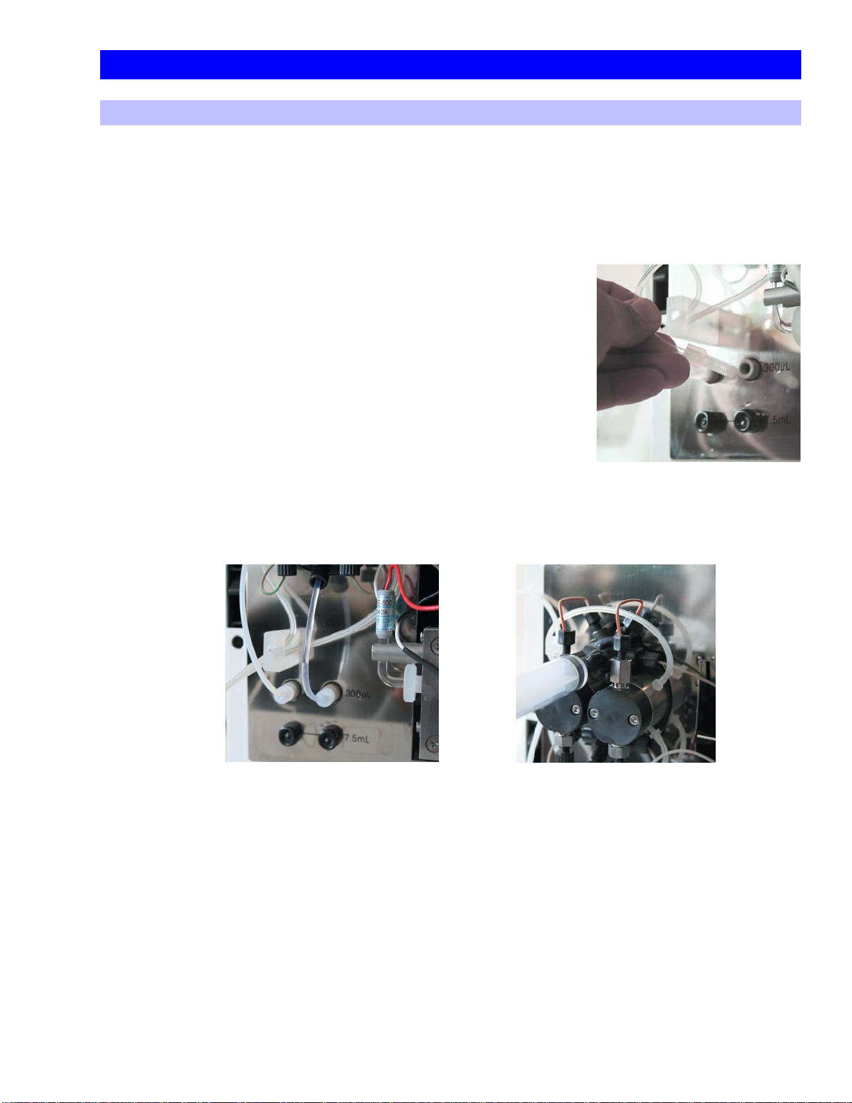
Two Channels, 300 μl and 7.5 ml
Two channels (upper and lower) are installed in the online degassing system. Either the 300 μl channel or
the 7.5 ml channel can be used. The 300 μl channel is more efficient at exchanging the liquid in the
degassing component. At a flow rate of 500 μl/min of mobile phase, the degassing efficiency is the
same between the two channels. There is no independent switch to turn on and off the degassing
system. The main power switch regulates the power of the degassing system.
6-1. If you think the degassing efficiency is reduced, you may diagnose the
problem by the following procedure:
• Replace the mobile phase at the end of the inlet tubing of the system with ultrapure water.
• Turn off the pump and use a syringe to aspirate 5 ml of mobile phase from the pump drain valve and
then close the valve. Leave the system off for 10 min. It is not necessary to remove the columns.
• Turn on the main power and listen to the degassing pump noise (not the HPLC pump). The pump is
supposed to stop in a few minutes. The pump has a function to create a vacuum chamber inside of
the degassing system to allow dissolved air to go through the tubing inside.
• If the degassing pump stops within 4.5 min, the degassing system is functional.
• If the pump works for 4.5 min continuously, the degassing system is likely to have a mechanical
problem. Please time precisely for 4 min. If the degassing pump runs for 5 min, the pump will stop
automatically to prevent overrunning regardless of whether the degassing component is working
properly or not.

8
HTEC-500
7. HPLC Pump Operation
Pay attention to the following points about the pump operation:
• Rinse behind the pump pistons with ultrapure water before and after use. Do not use any organic
solvents in the rinse solution. It is common that an air bubble or air segment may appear in the piston
wash line but it does not affect any functions.
• The mobile phase container should be a clean glass bottle. Do not use a plastic container.
• Put the mobile phase container on the same level as the HTEC-500.
Pump Outlet
Piston Wash Port
Check Valve (Outlet)
Pump Head
Piston Wash Port
Check Valve (Inlet)
nut
PEEK Tubing 0.75 mm ID
Easy Fit
(Tubing connected to the piston wash ports is silicon 3 1 mm)
PEEK Tubing 0.5 mm ID
OPEN
Drain
Fig. 7 Pump Parts and Drain
The drain valve and the drain port are integrated. Connect a syringe
to the drain port (as in the figure above) and turn the drain valve a
half circle. Use the syringe to suck out some mobile phase.
Check Valve
(Outlet)
Check Valve (Inlet)
Pump Head
Piston Seal
Backup Ring
O ring Wash Port
Head Guide
Piston
Diaphagm
Center Guide
Rod Assay
Fig. 8 Pump Details
9
HTEC-500
7-1. Run/Stop
Use the pump key to turn the pump on and off. When the pump is running, the pump light should be on
at the front of the system. Also, *PUMP* on the liquid crystal display (LCD) indicates the pump is running,
while -PUMP- indicates the pump is off.
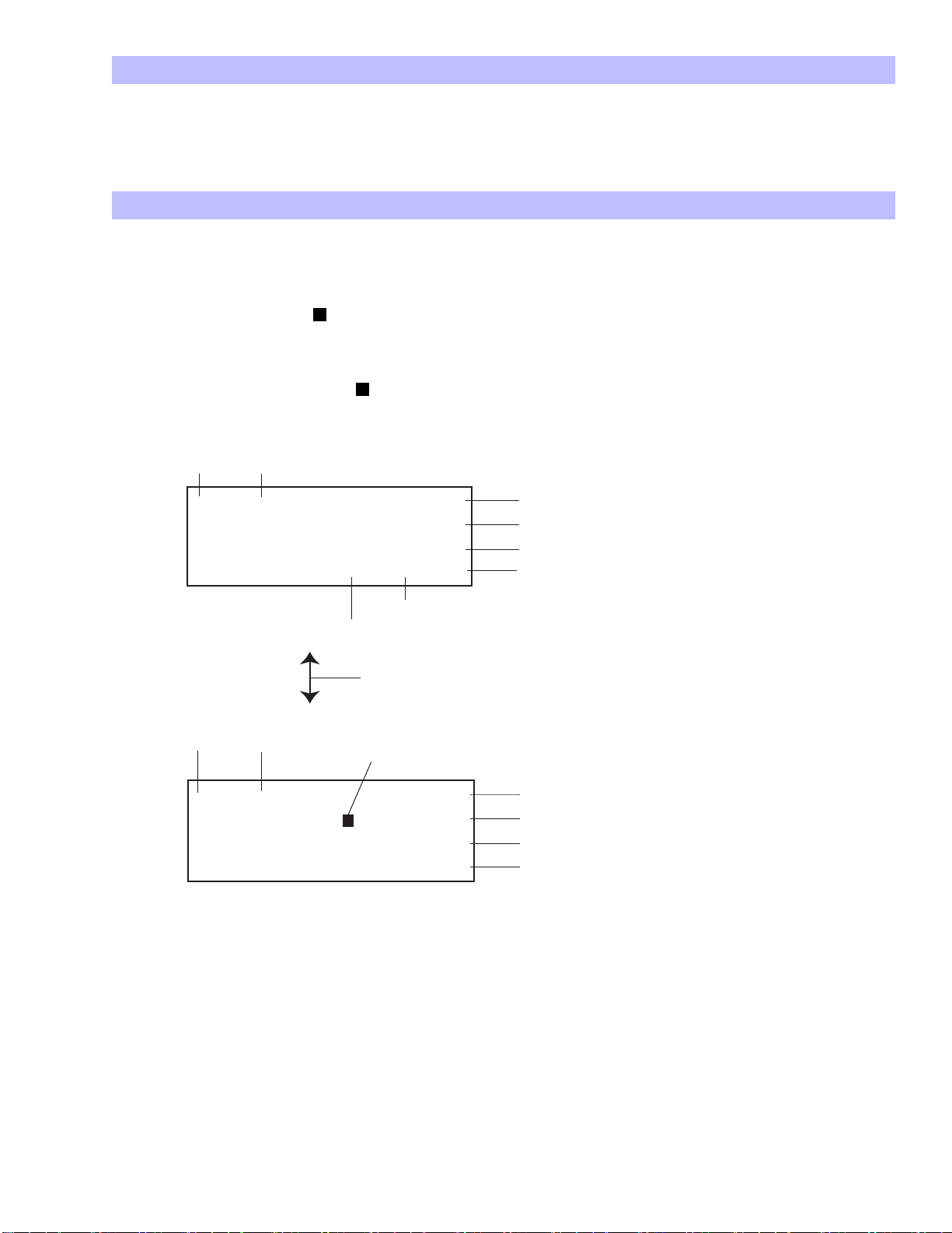
7-2. Flow Rate Setting
• Select the pump monitor by pushing the display key (the display key switches between the ECD and
the PUMP screen).
• Push the edit key once. ‘ ’ appears beside the flow rate (μl/min).
• Enter the adequate number from 1 to 750 using the 10 number keys.
• Push the edit key once more. ‘ ’ should now be beside pulse free mode.
Fig. 9 Display
*PUMP* Press 0.64MPa
FlowRate 200μL/min
PulseFreeMode ON
Press.Limit 14MPa
Indicates the pump is running.
Pressure status
Setting flow rate. (Use the 10 keys for setting)
Indicates the selected setting. Moves and makes changes using the edit key.
ON/OFF using the select key
Use the 10 keys for setting
-ECD- 01.54nA
APP
.Poten +400mV
TimeConst. 1.0sec
T
emp/Set 25.6/25˚CC
These bars indicate that the ECD is turned off.
Current status
Setting applied voltage (use the 10 keys for setting).
Most sensitive at 1.0 sec.
Noise is reduced at 3.0 sec. Select using the select key.
Indicates the thermocontroller is ON.
Cabinet setting
Actual temperature in the cabinet
Display can be switched between these two screens using the display key.

10
HTEC-500
7-3. Pulse Free Mode Setting
• After setting the flow rate, turn the pulse free mode on or off by pressing the select key.
• By pressing the edit key once more, the pulse free mode is set on or off and the cursor (‘ ’) is moved
to the next line.
7-4. Function of Pulse Free Mode
A. Pulsation Quenching
The HTEC-500 is equipped with a pulse free mode. This is a pulse quenching system. A computer
detects pulsatile flow as the pressure changes (this information is provided by a pressure sensor) and
controls the pistons movements during each stroke but does not influence the stroke cycle or the
flow rate. This feedback system works continuously when the mode is on. The pulse noise level and
the pistons movements converge in a constant period. When the pressure changes slightly due to
changes in the mobile phase conditions, temperature and so on, this pulse free mode improves the
pistons movements. The latency of this convergence is shorter at higher flow rates.
B. Flow Rate Compensation
Always turn the pulse free mode off before starting maintenance, exchange of mobile phase,
purging and so on, because the flow rate is different when the pulse free mode is on and when it is
off. Generally, the flow rate decreases under high pressure in a flow system. In order to compensate
for this speed loss, the pistons cycles are faster under high pressure when the pulse free mode is on
rather than when it is off. To avoid inconsistent retention times between pulse free mode on and off,
always have the pulse free mode on when you run the pump for sample analyses.
When the pulse free mode is on and a rapid pressure change occurs, the pump stops automatically
and signals to the connected autosampler to stop its operation. On the other hand, when this mode
is off, the piston always moves at a constant speed and passage. Even if the pressure changes, the
pump does not stop. When the pulse free mode is off, Error 1 may occur but Error 3 and 4 do not
occur. For details about pump errors, please see the next chapter.
11
HTEC-500
8. How to Fix Pump Errors and Problems
8-1. Less Flow Rate, Less Pump Pressure or Unstable Pump Pressure
There are a few possibilities to resolve these problems. Please try A to C as follows:
A. Remove Air from Pump Heads and Check Valves
If the pressure is unstable or lower than normal for the set flow rate, a small trapped air bubble in
one of the pump heads or the check valves could be the cause of this problem. To remove the air
bubble, please follow these steps:
1) Stop the pump.
2) Disconnect the pump inlet tubing at the outlet of the degasser.
3) Run the pump.
4) Open the pump drain valve and aspirate mobile phase slowly by using a syringe from the drain
port so that the pump inlet tubing gets a half an inch of an air segment in the pump inlet tubing.
5) Connect the pump inlet tubing back to the degasser. (see Fig. 11)
6) Aspirate the air you have inserted into the tubing along with mobile phase into the syringe.
(see Fig. 12)
7) Close the drain valve.
8) Wait for a few minutes and see if the pump pressure goes back to the previous level and is
stable.
If the problem does not get resolved, repeat these steps a few times and the pressure should
become normal.
Fig. 10
Fig. 11
Fig. 12

12
HTEC-500
B. Remove Air from Tubing Going to the Column
If these above steps don’t work, another cause of this problem could be that an air bubble(s) may
be trapped in the tubing between the pump and the (pre)column. To solve this, disconnect the
tubing upstream of the precolumn and pump mobile phase through until the air bubble(s) comes
out.
C. Wash the Pump
If the problem still persists, methanol is also effective in solving this problem. A contaminated inner
surface will trap air easier than a clean surface. This problem may happen when you do not use any
organic solution in the mobile phase. In some cases, a methanol wash may not work. If you use
more than a few percent of methanol in the mobile phase, please skip to the section on Error 3 in
chapter 8-3, page 13.
1) First, disconnect the columns from the line to prevent methanol from flowing through them.
When you remove any column, plug the inlet and outlet of the column as soon as possible. Also
plug the free end of the tubing which was connected to the precolumn or column to prevent air
coming in when you aspirate the solution from the pump drain valve.
2) Turn off the pump and replace the mobile phase with ultrapure water. Then open the purge
valve and aspirate the ultrapure water as it comes into the pump.
3) Run the pump and then close the valve. The plug on the free end of the tubing will pop out. The
pump needs to run for a few minutes to wash out the mobile phase from the tubing after the
pump. When aspirating from the purge drain using a syringe, the disconnected tubing, which
was connected to the column, must be plugged or air will be introduced through the aspiration
of solution from the drain valve by the syringe.
4) Now, you can stop the pump, replace the ultrapure water with methanol and repeat the above
procedure. Following this, replace the methanol with ultrapure water and then replace the
ultrapure water with mobile phase.
If these three treatments do not work, (1. Removing air from pump head, 2. Removing air form the
tubing, 3. Methanol wash) there is another possibility that some small dust or lint is trapped in one of
the check valves. Normally, this type of problem happens in the inlet check valve.
8-2. Types of Pump Errors
When the fluid flow system has some problems, an error message will appear on the LCD screen and
the pump will automatically stop. The types of errors and the main causes are described in chapter 8-3,
next page. When a pump error occurs, a contact closure signal is generated at the pump error out
signal terminal which is located on the right side of the system. If the ‘pump error out’ and ‘a signal in for
the emergency stop’ on your autosampler are connected by using signal cables, the upcoming run to
be processed by the autosampler will be stopped and you can avoid loosing samples after the pump
stops.
Table 1. Types of errors and their cause(s).
Error 3 and 4 only occur when the pulse free mode is on. Error 2 does not exist.
Cause
Current pressure is over the pressure limit setting.
Pressure decreases suddenly or there might be a leak.
Motor torque error
Error
1
3
4

13
HTEC-500
8-3. How to Fix these Errors
A push of the pump key clears the errors. If the same error occurs repeatedly, the problem can be
resolved by referring to the following:
Error 1
The pressure limit value may be set too low. If so, raise the limit value. The optimum pressure limit is
different for each column (see Table 2).
One reason for this error message is that there may be a blockage in the line. Check the precolumn first
by disconnecting the precolumn from the line. If the difference in pressure with the precolumn and
without the precolumn is more than 3 MPa, it is time to exchange the precolumn packing gel and the
upstream filter.
If the error is still not cleared, check the pressure differences of each part as you did for the precolumn
above by going from downstream to upstream of the part. This way you should identify the part which is
blocked. Cut the inlet about a few centimeters if the PEEK tubing is blocked. Use a cutter knife and take
care not to break the inside hole. As the tubing has a constant inner diameter, the blockage factor
cannot go deeper if it comes from upstream. If an autosampler is present, sometimes dregs of vial cup
can cause a blockage at the inlet tubing of the high pressure valve. Please disconnect the tubing at
the first port on the autosampler immediately after the injection port and cut the inlet of the tubing.
Table 2. Column type and recommended pressure limit setting
Column
AC-GEL, E-GEL
SC-3ODS, CA-5ODS,
SC-5ODS (Amino Acids)
PP-ODS
SC-5ODS
Pressure limit setting
8.0
15.0
10.0
12.0
14
HTEC-500
Error 3
The computer on the HPLC pump unit is programmed to display error 3 when one of the check valves
does not work properly. If the pressure sensor detects a rapid pressure decrease and cannot return the
pressure to the previous level within 12 rotations of the motor, error 3 is displayed. If you are running the
pump for maintenance, please switch off the pulse free mode.
Error 3 may occur for the following reasons (Treatments are also described below):
A. The tubing connection is not good. There is a leak somewhere in the high pressure zone between
the pump piston and the separation column. Check if there is any leak in the flow line. Typically, the
connection at an injector valve or at the column inlet may become disconnected. If you find it has
been disconnected, please re-connect it. A pressure reading of more than 150 MPa will lead to the
disconnection of fittings. Please check that your column is not too old and if the precolumn is
clogged.
B. Air needs to be removed from the pump. See chapter 8, page 11.
C. If air gets trapped in the pump frequently, make sure the connections are tight enough, the tubings
are not damaged and the elution degassing system is working properly (see also chapter 6,
page 7). The cause of resistance in the pumping system can be either that the mobile phase bottle
is at a lower position compared to the HTEC-500 or an inline filter is present upstream of the pump
(typically a tubing anchor filter in the mobile phase bottle is used). Check that the mobile phase
bottle is on the same level as the HTEC-500. Please remove the filter if you have one.
D. One of the check valves has lint, dust or something inside. This problem happens more frequently in
the inlet check valves located at the bottom of the pump head. Replace only the inlet check valve
having the problem by the method described below. If the problem persists even after this
exchange, the outlet check valve may be the problem.
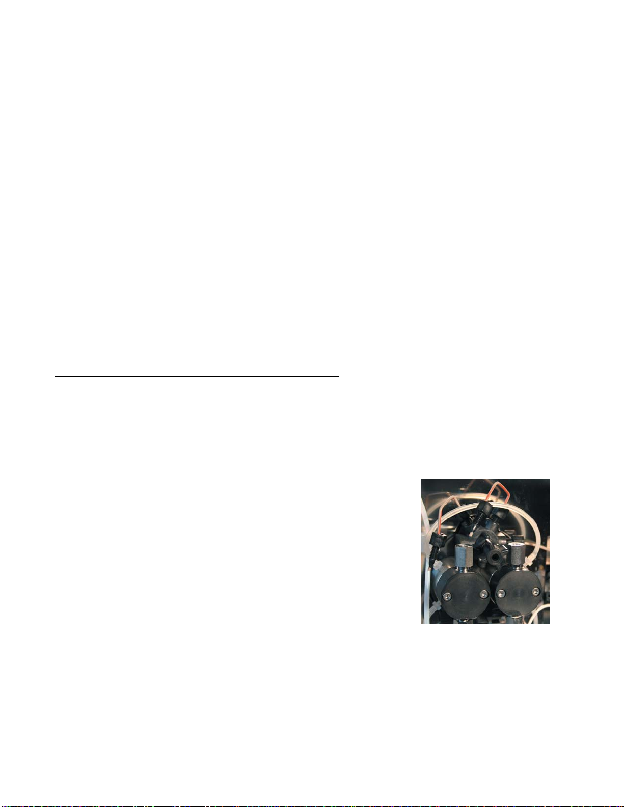
To find out which side of the pump has the problem perform the following steps:
• Keep the mobile phase level in the bottle at the same level or a few inches lower than the inlet
check valve.
• Release both the left and the right side of the hex nut that holds the
tubing at the outlet check valves (see fig. 13) and see if the mobile
phase comes up and at what speed it comes up at. When one of
the inlet check valves has failed, the mobile phase on that side
should come up significantly slower than the other side or may never
come up. You can also run the pump with the pulse free mode off
to check if the solution flows or not.
• Replace the failed inlet check valve with a new one (Inlet check valve, catalog #HT-IV)
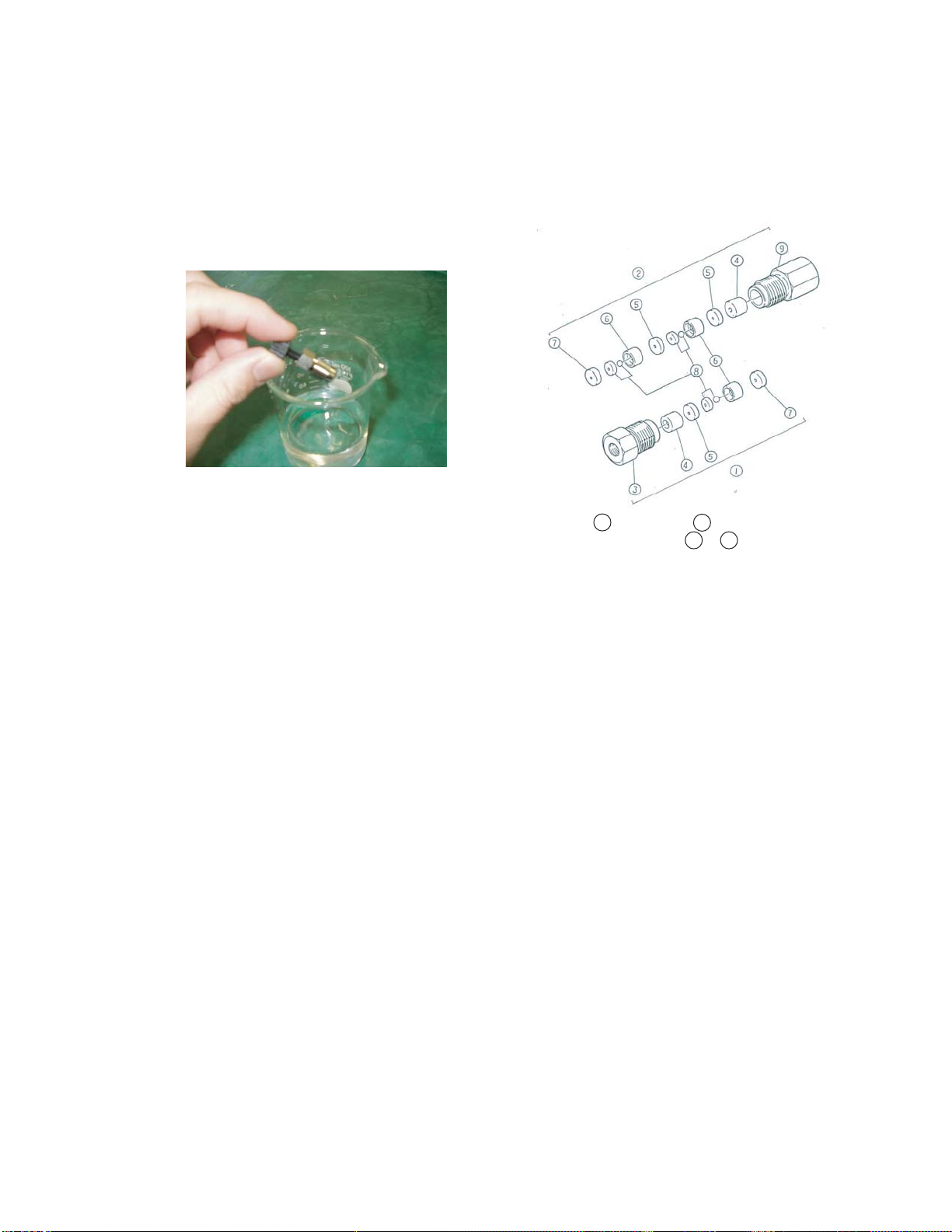
• Alternatively, the failed check valve can be cleaned but very detailed work is required to clean it
well. If you are not good at detailed work, simply exchange the valve with a new one. The check
valve structure is shown in Fig. 15. Please prepare 50 ml acetone in a 100 ml beaker. Then screw in
a stop-fit (a plug type fitting) into the valve and push out the inside parts into the acetone
(see Fig. 14). Clean all the parts with acetone and assemble it back to its original structure. Always
use clean forceps to pick up each part and do not touch them with your fingers.
Fig. 13
15
HTEC-500
How to clean the check valve
1. Remove the check valve assembly from the pump head.
2. Put some acetone in a small beaker. Over the beaker of acetone, fasten a column end plug to the
assembly. The end plug will help to push out the inside parts into the beaker of acetone. DO NOT
TOUCH any of the inside parts (parts #4–#7, shown in Fig. 15) with your fingers. Use tweezers to
handle them.
3. Assembling. Assemble as the smooth face of the seat ring faces to the ball (#8). The parts #7 is
reversible. Put the #7 on the table and push the #3 on #7.
Error 4
Error 4 occurs when the pump motor needs to generate more torque. This situation happens when the
pulse free program needs to quench difficult pulsations that have unusual pressure changes and cause
the pump motor to generate too much torque.
If this problem happens after a few rotations of the pump motors and it does not stop immediately after
starting the pump, it may be because the pump system has the same problem as described for error 3
and the computer generated too much torque on the pump motor (once you cancel the error 4 by
pressing the pump key, try to regenerate the error by running the pump). In this case, the treatment is
the same as described for error 3. Please refer to the section on error 3.
If this problem happens without the motor rotation after running the pump and if the pump stops
immediately after pressing the pump key, it is because of the failure of the power train or the pressure
sensor of the pump. Please contact Eicom to fix the power train.
Fig. 14
Fig. 15 1Inlet Valve, 2Outlet Valve
Do not touch 4to 7by finger.

16
HTEC-500
9. Manual Sample Injector and Autoinjector
9-1. Structure
At the back of the manual injector, the sample loop is connected to ports No. 1 and No. 4. The tubing
from the carrier pumps is joined to no. 2 port. No. 3 port outputs to the column. No. 5 and 6 are drain
ports. Whenever injecting into the manual injector, use the accessory syringe. If you need to inject more
than 25 μl, please order the 50 μl syringe (Eicom model number 705SNR). Do not connect any other
tubings to the drain port. This is to avoid any potential problems.
9-2. Operation of Manual Injector
Caution!
Do not use a syringe with a sharp needle. Always use a blunt needle.
The manual sample injector switches the flow by changing the lever knob position from LOAD to INJECT.
When introducing the sample into the manual sample injector, only the Hamilton Microsyringe type
702SNR or 705SNR is recommended.
A. Aspirate the sample into the microsyringe. If an air bubble generates inside of the syringe, please
flush out the solution with the air bubble and slowly re-aspirate. Generally the knob is set at INJECT
before and after the injection.
B. Insert the syringe needle until you feel a strong resistance (3 mm further than the point where you
feel a weak resistance).
C. Turn the knob to LOAD and push the plunger to inject the sample into the manual injector. Through
this step, the sample is injected into the loop.
D. Turn the knob from LOAD to INJECT immediately and smoothly. By moving the knob from LOAD to
INJECT, an electrical signal is also generated.
E. After completing these steps, remove the syringe and wash the syringe with ultrapure water. Please
wash the entire syringe each time between injections to avoid contamination.
After each injection, the needle port of the manual injector must be washed with ultrapure water
using the white port cleaner and a syringe.
When using an external injector, please refer to it’s user’s manual.
When comparing the concentration of different samples, inject the same volume every time.
Wash the syringe with hydrochloride periodically to keep it clean.
Table of contents
Popular Laboratory Equipment manuals by other brands

Metrohm
Metrohm 917 Coulometer manual

Integra
Integra PIPETBOY pro operating instructions

TESTO
TESTO 882 Brief instructions

Ocean Optics
Ocean Optics SpectroClip-R Installation and operation manual

Teledyne
Teledyne CETAC ASX-112FR Operator's manual

BASENHURT
BASENHURT Tebas-Economic EFka300 pH/Chlor Installation and maintenance instructions

Biosan
Biosan MMS-3000 User instructions

Horizon Fitness
Horizon Fitness FCSU-023 instruction manual

Metrohm
Metrohm 883 Basic IC plus manual

NEW BRUNSWICK SCIENTIFIC
NEW BRUNSWICK SCIENTIFIC BioFlo CelliGen 115 Guide to operations

Granville-Phillips
Granville-Phillips 835 Series instruction manual

Oxford Instruments
Oxford Instruments ANDOR Kymera 328i Series quick start guide


