erlab Captair Flex S Series User manual

User Manual
TM
Please consider the environment before printing this document
User Manual
Captair®Flex™
S-M-SD-XLS
Kunshan erlab D.F.S Co.,Ltd
100 Liu Shi Jing Road Kunshan Development Zone PengLang Jiangsu Province
Tel : +86 (0) 512 5781 4085 - Fax . : + 86 (0) 512 5781 4082 - E-mail : Sales.china@erlab.com.cn
01/2010 - T
echnical data are not contractual. erlab®CHINA reserves the right to modify the present document without prior notice.

User Manual
TM
2
Congratulations!
By choosing Captair® Flex™ ductless filtering fume hoods, you have
chosen an efficient, reliable way to ensure safety.
Your Captair® Flex™ filtering fume hood guarantees that you are
protected when working with chemicals that pose an inhalation risk for
the user.
Your fume hood functions based on the recirculation of filtered air, which
makes it possible to use high-efficiency filters to trap toxic particles
and molecules and to recycle this air within the laboratory. The air
downstream from the hood’s modular filtration column, which uses the
new Flex™ technology, is thus free of all chemical pollutants.
Nevertheless,theeffectivenessofthissystemisdirectlydependent
upon it being used correctly and monitored by its users. Your
laboratory may also benefit from ergonomic, economic, and ecological
advantages provided by the Captair® Flex™ fume hood throughout its
life cycle.
Do you want to work in a 100% safe environment year after year?
A careful reading of this manual is a must!
Designed to protect the user,
the environment and your budget.

User Manual
TM
3
€
€
Your new Captair®Flex™ ductless filtering fume hood
offers several advantages from day one:
Benefit from the use of an immediately
available unit, easy to relocate.
Captair®Flex™ filtered enclosures can be moved depending
on the protection needs of the laboratory and can be easily
relocated without disturbing room air balance.
Eliminate installation costs
The installation of a captair®Flex™ filtered enclosure is
quick and easy. There is no need for a ductwork linked
to an air supply / air extraction system, in comparison to
traditional ducted systems. A single electrical outlet is all
that is needed to make it work Its setting up can be realized
at any time, without any complex forward planning. Do not
hesitate to compare this cost to a traditional ducted fume
hood cost.
Protect the environment
Since no ductwork is required, a captair®Flex™ filtered
enclosure totally eliminates the direct discharge of
pollutants into the atmosphere and therefore contributes
to the protection of the environment. Furthermore, a
captair®Flex™ filtered enclosure does not generate any
pollution linked to energy production unlike a traditional
ducted fume hood.
Achieve significant energy savings
Ductwork air balance is essential to the proper operation of
a traditional ducted fume hood however; it is also the source
of very important energy consumption. In fact, captair®
Flex™ filtered enclosures do not generate any energy costs
associated with the use of expensive extraction systems
or conditioned air supplies. Operational costs remain at a
minimum even when taking into account filter changes.

User Manual
TM
4
Contents
Introduction Page 2
Page 5
Page 27
Page 35
Page 52
Protecting yourself
Getting started
Maintenance
Warning
- Monitoring air face velocity
- Manually detecting filter saturation
- Automatically detecting filter saturation
- Replacing the filters
- The revolving system
- Cleaning and maintenance
- Via the E.S.P. program (Erlab Safety Program)
- Via AFNOR NF X 15-211: 2009 standard
- Flex™ technology
- Description of the control box
- First start-up
- Navigating the digital display screen

User Manual
TM
5
Getting started
- Flex™ technology
- Description of the control box
- First start-up
- Navigating the digital display screen

User Manual
TM
6
By combining molecular and particulate filtration
technologies,erlab® was able to devise the new Flex™
modular filtration column technology.
This single device can thus be configured to meet the
protection needs of your laboratory.
This flexibility was made possible by creating stackable,
one-size-fits-all filtration cartridges—an innovation
that is key to your new Captair® Flex™.
This innovation developed by the erlab® R&D
laboratory offers unprecedented flexibility, adaptability,
and savings.
Your device can be quickly reconfigured and can be
easily used for other applications.
Possible configurations for your Captair® Flex™ fume hood
FLEX™ TECHNOLOGY
A modular filtration column which provides
unprecedented adaptability and flexibility.
N’hésitez pas à tout moment à entrer en contact avec votre agent
ESP pour configurer avec lui la solution de protection adéquate à vos
besoins
You may contact your E.S.P. agent at any time
to confirm the safety parameters
related to the use of your device!
Manipulated chemicals/ Applications
1
5
3
4
2
6
7
4
8
1
5
3
4
2
6
7
4
8
256 mm
Carbon filter
Fan
256 mm
H14 HEPA filter
Fan
340 mm
Carbon filter
H14 HEPA filter
Fan
445 mm
Carbon filter
Carbon filter
H14 HEPA filter
Fan
Carbon filter
Carbon filter
H14 HEPA filter
Fan
Carbon filter
H14 HEPA filter
Fan
Carbon filter
Carbon filter
Fan
Liquids
For dilutions, titrations,
extractions, transfers, …
Solids
For sievings, grindings,
weighings, formulations,
compressions…
Liquids & solids
For dissolutions, filtration,
extractions, …
Handlings in
clean rooms
Up to class ISO 5 rooms
1C
1P
1P 1C
1C 1P
1P 2C
2C 1P
2C
Class 2 according to the
NF X 15-211 :2009 standard
Class 1 according to the
NF X 15-211 : 2009 standard
Class 1 according to the
NF X 15-211 : 2009 standard
Class 1 according to the
NF X 15-211 : 2009 standard
Class 2 according to the
NF X 15-211 :2009 standard
Class 2 according to the
NF X 15-211 :2009 standard
User Manual
TM
7
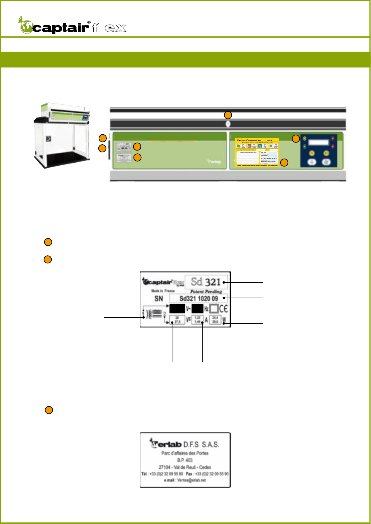
Master switch
Model label
Name of the manufacturer or their representative
1
2
3
12
3
4
5
6
Fume hood model
Fume hood serial number
Power in Watts
IntensitySupply
voltage
Supply voltage
and frequency
supported
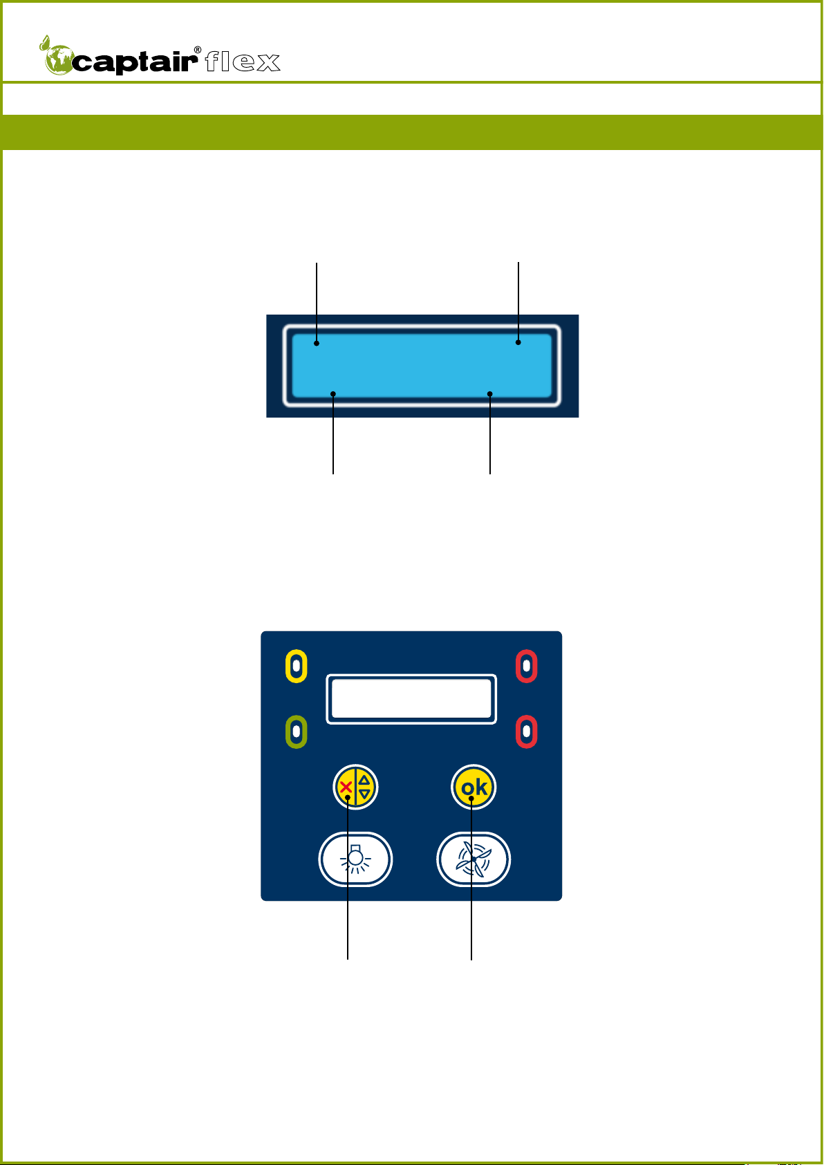
DESCRIPTION OF THE CONTROL BOX
7
100-240 47-67
User Manual
TM
8
4
5
6
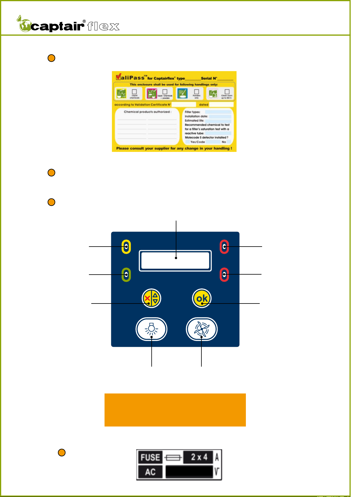
Valipass® form: Refer to the Valiquest® section for details.
Control panel
Sampling port for the manual filter saturation test or for an ambient air sensor when
the machine is equipped with the Molecode™ S option.
Yellow indicator light
Green indicator light
Red indicator light
Red indicator light
Digital display screen
Confirmation buttonNavigation button
Ventilation
switch
Internal light
switch
For information on the various scenarios related
to the triggering of the device’s indicator lights and
audible alerts, refer to the EVENT ALERTS section
of the FIRST START-UP chapter.
7Fuse tag.
100-240
User Manual
TM
9
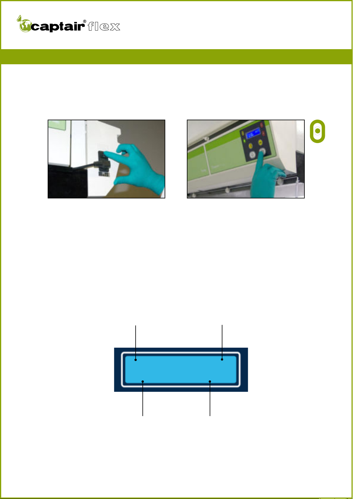
Default screen display
Information related to the filters
Month and year during which
the main filter was installed
Number of fans installed
in the device.
Operating time of the device
based on the cycle setting of
the Timer™
Filter FANS: XX
MM/Year HH:MN
Turn on the device using the switch located on the left side of the control panel.
Activate the device’s ventilation system using the ventilation button located underneath
the digital display screen.
The green indicator light comes on and the screen displays the DEFAULT SCREEN DIS-
PLAY.
The Timer™ begins to count down based on its factory settings (60 hours).
You have carefully followed the steps described in the assembly instructions and your
Captair® Flex™ fume hood is ready to use.
FIRST START-UP

User Manual
TM
10
The Timer™
The Timer™ keeps track of the amount of time that your Captair® Flex™ fume hood
has been in operation in order to remind the user when it is necessary to carry out a
periodic filter saturation test.
The default setting (factory setting) is 60 hours (as required by NF X 15-211: 2009 stan-
dard).
An alarm will alert the user to check that the filter is still able to function properly.
A pre-warning alarm may go off between 0 and 10 hour(s) before the Timer™ alarm
(according to factory settings).
Activation / Deactivation:
It is possible to activate or deactivate the Timer™ and its pre-warning alarm.
To make use of this functionality please refer to the section on “Navigating the digital
display screen.”
In order to guarantee that your device functions properly and in order to ensure your
safety, your Captair® Flex™ fume hood is equipped with a monitoring system linked to
the air flow parameters and to the device’s Flex™ technology.
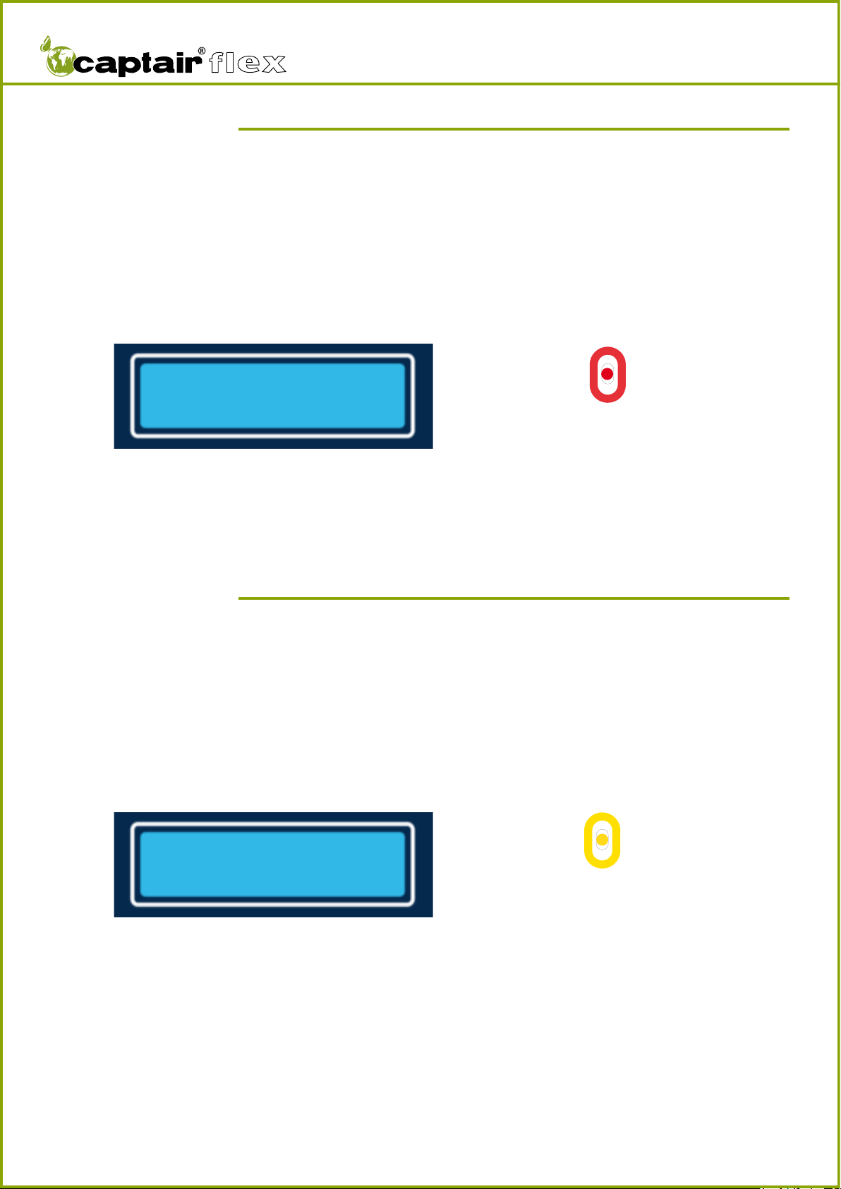
Event 1:
Fan control problem
Event conditions:
The fume hood does not reach the proper number of rotations per minute (RPMs) wi-
thin a period of ten seconds after the ventilation system has been started.
This section describes all of the audible and visual alerts triggered by the alarms included
in your Captair® Flex™ fume hood.
Solution:
Contact your maintenance service as quickly as possible.
FAN
CONTROL FAILURE
Display screen
Event alerts
Alarm type
Yellow indicator light on, constant
Intermittent audible alarm
User Manual
TM
11
Event 2:
Fan out of order
Event conditions:
The rotation speed of the fan is less than 700 RPM.
FAN
OUT OF ORDER
Display screen Alarm type
Solution :
Contact your maintenance service as quickly as possible.
Solution :
Press the navigation and confirmation buttons simultaneously and release them to deacti-
vate the alarm.
The red indicator light will stay on.
The concentration at the exhaust of a filter nearing its saturation point can build up very
quickly. Consider replacing the filter.
Event 3:
Solvent detected in the sampling chamber
Event conditions:
The detection limit of the Molecode™ S unit has been reached.
FILTER
NEAR END OF LIFE
Display screen Alarm type
Red indicator light on, constant
Continuous audible alarm
Yellow indicator light on, constant
Intermittent audible alarm

User Manual
TM
12
Event 4:
Solvent detected 2
Event conditions:
The detection limit of the Molecode™ S unit has been surpassed.
CHANGE
FILTER(S)
Display screen Alarm type
Solution :
It is necessary to replace the filter.
Please contact your maintenance service.
Solution :
Press the navigation and confirmation buttons simultaneously and release them to deacti-
vate the alarm.
Identify the source of the pollution.
Event 5:
Pollutant detected in the ambient air of the laboratory
Event conditions:
The ambient air sensor on the front detects that pollution is likely in the ambient air of
the laboratory.
LABORATORY
POLLUTION
Display screen Alarm type
Red indicator light on, constant
Continuous audible alarm
Red indicator light on, blinking
Continuous audible alarm

User Manual
TM
13
Event 7:
Pre-warning alarm maintenance
Event conditions:
If the Timer™’s pre-warning alarm is activated, this alarm is triggered when the counter’s
value is less than the pre-warning value.
FILTER TEST
H / MN
Display screen Alarm type
Solution :
Press the navigation and confirmation buttons simultaneously and release them to deacti-
vate the alarm.
Consider checking whether or not the filter is saturated.
Refer to the maintenance section of this manual.
Event 8:
Maintenance
Event conditions:
The value of the Timer™ is equal to zero.
FILTER
TEST
Display screen Alarm type
Solution :
Press the navigation and confirmation buttons simultaneously and release them to deacti-
vate the alarm.
Consider checking whether or not the filter is saturated.
Refer to the maintenance section of this manual.
Yellow indicator light on, blinking
Intermittent audible alarm
Red indicator light on, constant
Continuous audible alarm
User Manual
TM
14
DEFAULT SCREEN DISPLAY
Information related to the filters
Month and year during which
the main filter was installed
Number of fans
installed in the device
Operating time of the device
based on the cycle setting of
the Timer™
Filter FANS: XX
MM/Year HH:MN
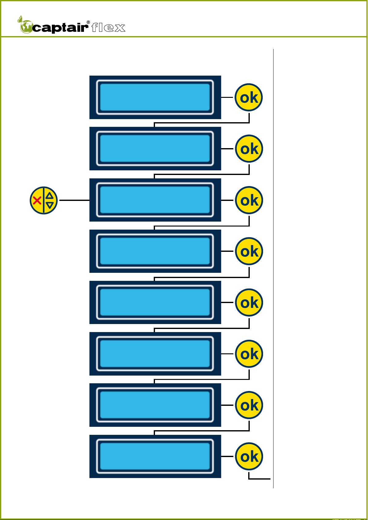
ACCESSING THE MENUS
To access the menus of the screen, press down
on the navigation and confirmation buttons
simultaneously.
The menus will appear when the buttons are
released.
NAVIGATING THE DIGITAL DISPLAY SCREEN

User Manual
TM
15
Notes:
Allows the user to view the sta-
tus of the fume hood. Press the
confirmation button to access
the contents of the menu.
Allows the user to modify the
parameters of the screen display
language.
Press the confirmation button to
access the contents of the menu.
Allows the user to update
information after testing for filter
saturation.
Press the confirmation button to
access the contents of the menu.
Allows the user to modify the
limit settings of the Molecode™
S detection sensor.
Press the confirmation button to
access the contents of the menu.
Allows the service engineer to
set the ventilation flow rate.
Protected by an access code.
Press the confirmation button to
access the contents of the menu.
Allows the user to activate or
deactivate the Timer™. Press the
confirmation button to access
the contents of the menu.
Allows the service engineer to
access the device’s configuration.
Protected by an access code.
Press the confirmation button to
access the contents of the menu.
Allows the user to exit the main
menu.
Press the confirmation button to
display the default screen display.
1 Main Menu
MAIN MENU
>Hood State
1-1
Hood State
>Set Language
1-2
Set Language
>Test filter
1-3
Test filter
>Set Threshold
1-4
Set Threshold
>Set Setpoint
1-5
Set Setpoint
>Set Timer
1-6
Set Timer
>Man. Menu
1-7
Man. Menu
>Exit
1-8

User Manual
TM
16
Notes :
This number corresponds to the
number of fans detected by the
device.
It may be between 1 and 4 de-
pending on the Captair® Flex™
model in question. (Refer to the
technical specifications listed at
the end of the manual.)
Indicates the presence or
absence of the Molecode™ S
option on your device.
This number indicates the
sensitivity on the Molecode™
S detection sensor included on
your device. If the device is not
equipped with a Molecode™, the
contents of this screen are not
visible.
RPM: rotations / minute.This
number indicates the rotation
speed of each fan. It may be
between 0 and 3000 depen-
ding on the Flex™ technology
installed in your device and on
the factory settings.The rotation
speed must be the same for each
fan installed, +/- 5%.
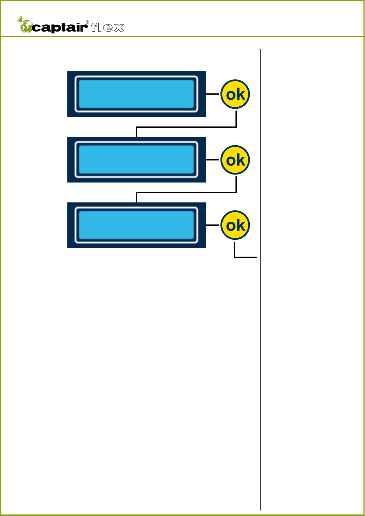
Display the Hood Stat menu.
1-1 Hood State
1-1-1
1-1-2
1-1-4
1-1-3-1
Threshold Sensor
Value : XXX
Number of fan
XX
RPM
01:XXXX 02:XXXX
03:XXXX 04:XXXX
Solvent Sensor
YES
MAIN MENU
>Hood State
1-1-3-2
Solvent Sensor
NON

User Manual
TM
17
By default the screen displays the
name of the factory-set naviga-
tion language. Other possible
display languages: French, Spanish,
German, and Italian.
Notes:
Allows the user to modify the
language displayed on the screen.
Confirm the chosen language to
save the selection.
Display the current navigation
language.
Display the Set Language
menu.
Display the Set Language
menu.
Confirm the chosen language to
save the selection.
Confirm the chosen language to
save the selection.
Confirm the chosen language to
save the selection.
Set Language
1-2
1-2-1
Actual Language
English
Change Language
English
Change Language
French
Change Language
Spanish
Change Language
German
Change Language
Italian
Hood State
>Set Language
1-2-2-1
1-2-2-2
1-2-2-3
1-2-2-4
1-2-2-5
User Manual
TM
18
Notes:
N.B.: accessing this menu
interrupts the ventilation
system of your device. It is
strongly recommended to
access this menu after the
filter saturation tests have
been performed. Press the
confirm button to proceed
to the next step.
Displays the sensitivity value
of the current sensor as sto-
red in the device’s memory
or previously modified.
If the Molecode™ S is not
installed on the device,
screens 1-3-5, 1-3-6, and 1-3-7
do not display.
Allows the user to adjust the
sensitivity value of the unit after
a new filter has been installed.
Scroll through the numbers using
the scroll button and confirm
each digit using the confirmation
button.
Confirm the previously selected
value.
Displays the month, year, and
operating time of the device after
a new filter has been installed in
the Manufacturer menu.
Parameter reset menu after a
new filter has been installed.
Allows the user to confirm
the installation date of the
new filter and to reset the
Timer™ if the Timer™ is ac-
tivated according to factory
settings. If the Timer™ is
not activated,“H:Mn” is not
displayed on the screen.
Allows the user to indicate the
new filter installation date.
Display the Test filter menu.
Test filter
1-3
1-3-1
Test filter
New filter
New filter
Month/Year H:Mn
Confirm ?
Month/Year H:Mn
Date : MM XX
YY XXXX
Threshold Sensor
Value : XXXX
Threshold Sensor
Value : XXXX
Confirm
Value
Set Language
>Test filter
1-3-7
1-3-6
1-3-5
1-3-4
1-3-3
1-3-2
Display the 1-3-2-1 menu
User Manual
TM
19
Notes :
N.B.:Accessing this menu inter-
rupts the ventilation system of
your device. Press the confirm
button to proceed to the next
step.
After verifying the condition of
the filter via a saturation test,
display the installation date and
operating time of this filter.
By pressing the confirm button,
the Timer™ is reset according to
the factory configuration if the
Timer™ is activated.
Display the Test filter menu.
Test filter
1-3
1-3-2-1
Test filter
Good Filter
Good Filter
Month/Year H:Mn
Confirm ?
Month/Year H:Mn
1-3-2-2
1-3-2-3

User Manual
TM
20
Notes:
N.B.: accessing this menu inter-
rupts the ventilation system of
your device. Press the confirm
button to proceed to the next
step. IMPORTANT: this menu
only appears if the device is
equipped with a Molecode™ S.
Displays the sensitivity value of
the Molecode™ S unit as confi-
gured in the factory or previously
modified. Scroll through the
numbers using the scroll button
and confirm each digit using the
confirmation button.
Allows the user to confirm the
selected value.
Display the Set Threshold
menu
Set Threshold
1-4
1-4-1
Threshold Sensor
Value : XXXX
Confirm XXXX ?
1-4-1
Test filter
>Set Threshold
This manual suits for next models
3
Table of contents
Other erlab Laboratory Equipment manuals


