Eider Biomasa WATT 10 PRO Manual

IMPORTANT:
READ
RIGOROUSLY
one.The guarantee is valid from the first ignition carried out by an authorized technician.
2.Do not overturn or place the product in a horizontal position during the transport phase.
3.The installation of the stove must be carried out by a qualified technician following current local
regulations.
Four.If ignition fails, or in the event of a blackout, before repeating the ignition,
RIGOROUSLY empty the burner. Failure to follow this procedure may cause the door
glass to break.
5.DO NOT MANUALLY PUT pellets into the burner to light the stove more easily.
6.In the event of abnormal behavior of the flame and in all other cases, NEVER SWITCH OFF
the stove by cutting off the power supply, use the shutdown button. Cutting off the
electricity means preventing the evacuation of smoke.
7.If the ignition phase is prolonged (wet or poor quality pellets) and favors the
formation of excessive smoke inside the combustion chamber, it is advisable to open
the door to evacuate it and keep in a safe position during this operation.
8.It is very important to use good quality and certified pellets. Using poor quality
pellets can cause incorrect operation and, in some cases, break mechanical parts, for
which the company is exempt from all responsibility.
9.Ordinary cleaning (burner and combustion chamber) must be carried out daily. The
company is not responsible for anomalies derived from non-compliance with said work.
2

The company Eider Biomasa is exempt from all responsibility for
damages caused to people or things derived from non-compliance with
the points highlighted above and for products not installed
according to current local regulations.
3

INDEX
01. SAFETY WARNINGS.................................................. .................................................. 6
02. GENERAL SAFETY REGULATIONS .................................................. ................................. 7
03. THE SMOKE OUTLET........................................... ................................................................ ............. 9
04. FINISHING OF CHIMNEY............................................ ................................................................ ........ eleven
05. SHOT ................................................ ................................................................ ................................. 12
06. EFFICIENCY OF THE STOVE .................................. ................................................................ ........ 13
07. INSTALLATION INSTRUCTIONS .................................................. ................................. 14
08. MICRONOVA N100 ELECTRONICS WITH 3-BUTTON LED DISPLAY .................................... 17
8.1 Correct operation and control regulation devices.................................................. .............17
8.1.1 Console ........................................ ................................................................ ......................................... 17
8.1.2 Meaning of the LEDs............................................ ................................................................ ...................... 17
8.2 The menu ................................................ ................................................................ ..................................................18
8.2.1 User menu............................................ ................................................................ ............................ 18
8.2.2 Menu 01 – set clock............................................ ................................................................ ............................ 19
8.2.3 Menuor02 – timer set................................................... ................................................................ .................... twenty-one
8.2.4 Menu 03 – language selection ................................................ ................................................................ ........ 2. 3
8.2.5 Menu 04 – stand-by mode .......................................... ................................................................ ................ 2. 3
8.2.6 Menu 05 – buzzer mode.................................................. ................................................................ ............ 2. 3
8.2.7 Menu 06 – initial load ................................................ ................................................................ ..................... 24
8.2.8 Menu 07 – stove status ................................................ ................................................................ ................. 24
8.2.9 Menu 08 – technical settings ................................................ ................................................................ ............. 24
8.2.10 Menu 09 – output ............................................ ................................................................ ............................ 24
8.3 User functions................................................... ................................................................ .....................................25
8.3.1 Igniting the stove .................................................. ................................................................ .................... 25
8.3.2 Pellet loading .................................................. ................................................................ ...................... 25
8.3.3 Fire present ................................................ ................................................................ ............................. 26
8.3.4 Stove at work............................................ ................................................................ ............................ 26
8.3.5 Modification of the set heat output .................................................. ............................ 26
8.3.6 Changing the room temperature setting .................................................. ............ 27
8.3.7 The room temperature reaches the set temperature (SET temperature) ............................. 27
8.3.8 Stand-by.................................. ................................................................ ......................................... 27
8.3.9 Turning off the stove ................................................ ................................................................ ...................... 29
8.4 Alarms ................................................ ................................................................ ................................................................ ............29
8.4.1 Electric blackout alarm .................................................. ................................................................ ................. 29
8.4.2 Smoke temperature probe alarm.................................................. ................................................................ 29
8.4.3 Smoke overtemperature alarm .................................................. ................................................................ 29
8.4.4 Faulty smoke encoder alarm .................................................. ................................................................ ... 29
8.4.5 Absence ignition alarm............................................ ................................................................ ............ 30
8.4.6 Absence of pellets alarm ............................................ ................................................................ ..................30
8.4.7 Thermal safety overtemperature alarm .................................................. ................................. 30
8.4.8 Absence of depression alarm ............................................ ................................................................ ............ 30
8.5 Connections ................................................ ................................................................ ............................................31
4

INDEX
09. CLEANING AND MAINTENANCE ................................................ .................................................. 32
09. Model A
9.1 Cleaning the surfaces ................................................... ................................................................ ......................32
9.2 Cleaning the metal parts .................................................. ................................................................ .................32
9.3 Cleaning the burner and its support ................................................ ................................................................ .........33
9.4 Cleaning the deflector ................................................ ................................................................ ............................33
9.5 Ash container ..................................................... ................................................................ ............................33
9.6 Cleaning the glass ................................................... ................................................................ ..................................33
9.7 Cleaning the fans ................................................... ................................................................ ...................33
9.8 End of season cleaning ................................................... ................................................................ ...................33
9.9 Cleaning the smoke extraction system
9.10 Replacing the glass ................................................... ................................................................ .......................3. 4
9.11 Annual maintenance by the Technical Assistance Center ................................................ ...................3. 4
9.12 Operations to carry out each station before switching on................................................. .........................3. 4
10. DAILY CLEANING ................................................ ................................................................ ................. 35
10.1 Introduction ................................................ ................................................................ ..................................35
10.2 Daily cleaning ................................................ ................................................................ ....................................35
10.3 Responsibility of the manufacturer.................................................. ................................................................ .............35
11. TROUBLES AND POSSIBLE SOLUTIONS................................................... .................................... 36
12. ANNEX RELATING TO THE WARRANTY AND THE USER'S SAFETY ............................................. 38
12.1 General information
12.1.1 IMPORTANT .................................... ................................................................ ............................. 38
12.1.2 Capacity and performance depending on model............................................ ......................................... 38
12.1.3 First ignition ................................................ ................................................................ ............................ 38
12.2 Installation and operating instructions
12.2.1 Installation and equipment safety ................................................ .................................................... 38
12.2.2 Installation of security elements in the installation.................................................. .................... 39
12.2.3 Commissioning, regulation and operation .................................................. ............................. 39
12.2.4 Recommended types of fuels .................................................. ...................................... 40
12.3 Maintenance
12.3.1 IMPORTANT .................................. ................................................................ ............................. 40
12.4 Warranty
12.4.1 Legal Guarantee .................................... ................................................................ ............................. 40
12.4.2 Commercial Guarantee (Annex I).................................................. ................................................................ ..........40
5

01. SAFETY WARNINGS
The stoves are manufactured in accordance with the EN13240 (wood-burning stoves) EN 14785 (pellet stoves) and EN 11815 (wood-burning
stoves and thermo-stoves) regulations, using high-quality, non-polluting materials. To better use your stove, it is recommended to follow the
instructions in the following brochure.
Read this manual carefully before use or any maintenance operation.
The objective of Eider Biomasa is to provide the greatest amount of information to guarantee a safer use and avoid
damage to people, things or parts of it.
All stoves are tested internally before delivery, therefore it is possible to find residues inside.
KEEP THE MANUAL FOR FUTURE REFERENCE
BEFORE ANY NEED OR CLARIFICATION, CONTACT A
AUTHORIZED DEALER
-Installation and connection must be carried out by qualified personnel in compliance with European (UNI 10683) and
national regulations, local regulations and the attached assembly instructions. The electrical installation of the place where
the stove is installed must be carried out in accordance with current regulations.
Combustion of waste, in particular plastic material, damages the stove and the flue, and is also prohibited by
the law on protection against emissions of harmful substances.
Never use alcohol, gasoline or other highly flammable liquids to light the fire or revive it during operation.
Do not put a greater amount of fuel in the stove than that indicated in the brochure. Do not
modify the product.
It is forbidden to use the appliance with the door open or with the glass broken.
Do not use the appliance for example as a clothesline, support surface or ladder, etc. Do not
install the stove in bedrooms or bathrooms.
-
-
-
-
-
-
-
6

02. GENERAL SAFETY REGULATIONS
-Only use this stove as described in this manual. Any other use not recommended by the manufacturer may
cause fires or accidents to people.
Make sure that the type of power supply complies with what is indicated on the data plate (220V~/50Hz). This
product is not a toy. Children must be adequately supervised so that they do not play with the appliance. This
appliance must not be used by people (including children) with reduced physical, sensory or mental capabilities, or
without the necessary experience and knowledge, unless a person responsible for their safety controls their use of
the appliance or gives them the pertinent instructions for use.
If the appliance is not used or for cleaning reasons, disconnect the power supply from the mains.
To disconnect the stove, place the switch in position O and remove the plug from the socket. Just pull the plug, not the
cord.
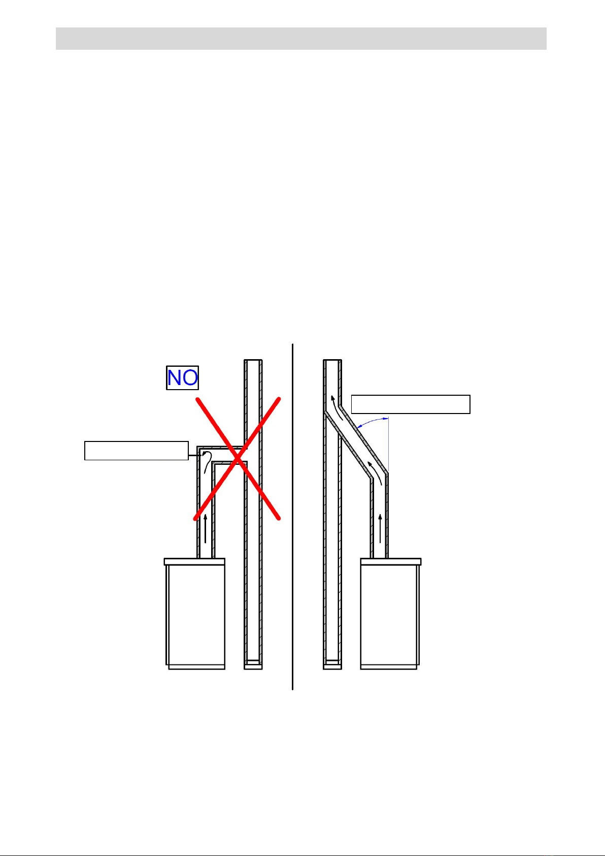
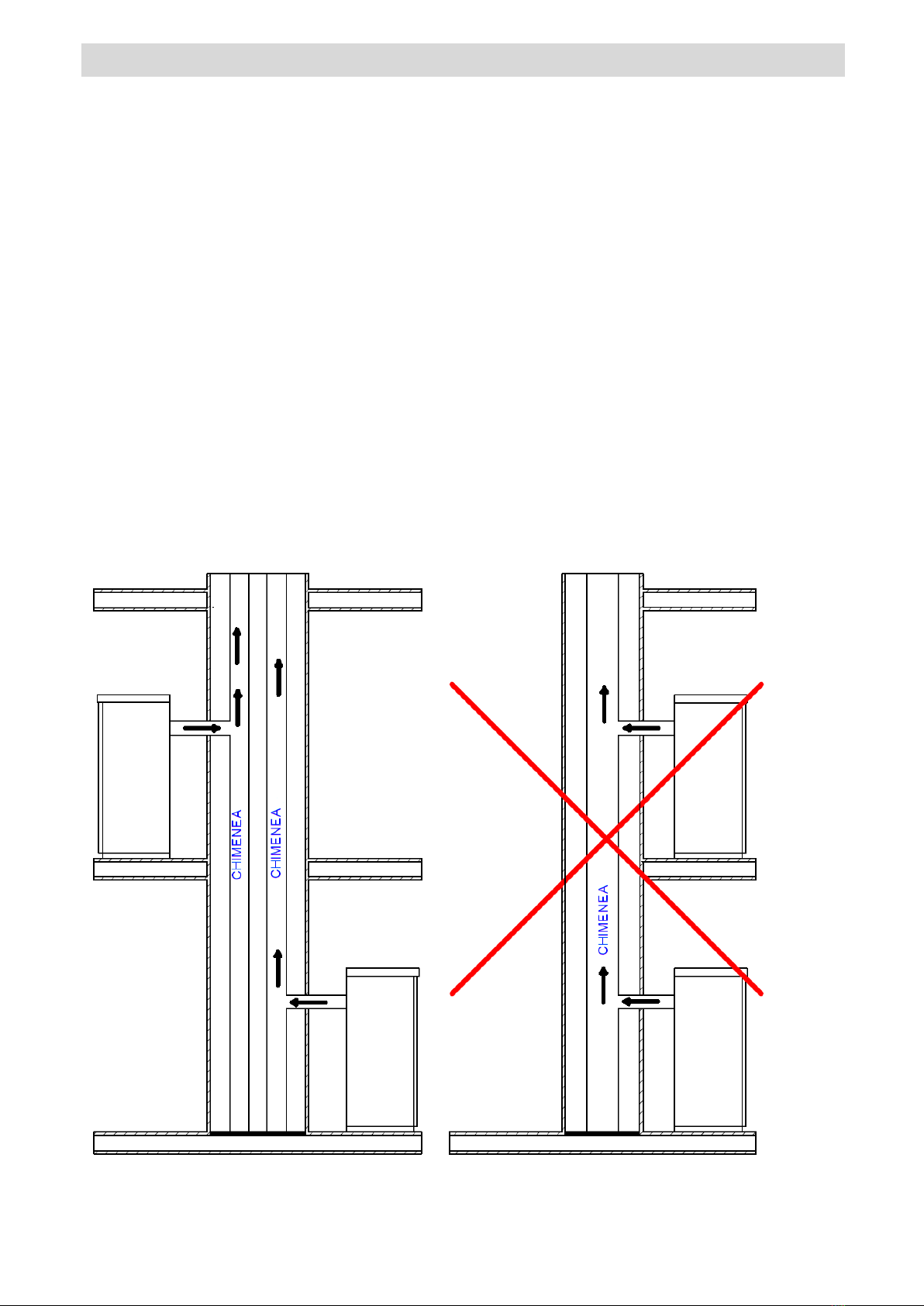
Under no circumstances close the combustion air inlet and smoke outlet openings.
Do not touch the stove with wet hands because it is equipped with electrical components.
Do not use the appliance with damaged cables or plugs. The appliance is classified as type Y, that is,
the power cord must be replaced by a qualified technician. If the power cord is damaged, it must be
replaced by the manufacturer, its technical assistance service, or similarly qualified personnel.
Do not put anything on the cable and do not bend it.
The use of extensions is discouraged, as the extension can become hot and cause a fire hazard. Never use a
single extension to run more than one appliance.
During normal operation, some parts of the stove, such as the door, the glass and the handle, can
reach high temperatures. Therefore, pay attention to the case, especially for children. Consequently,
avoid contact of unprotected skin with the hot surface.
ATTENTION! DO NOT TOUCH the DOOR WHERE THE FIRE IS, the GLASS, the HANDLE or the SMOKE OUTLET PIPE
without adequate protections DURING OPERATION: The strong heat developed by the combustion of the pellets
heats them up!
Keep flammable materials, such as furniture, pillows, blankets, papers, clothes, curtains, etc., at a distance of
1 m from the front and 30 cm from the sides and rear.
Do not immerse the cable, the plug or any other part of the appliance in water or other liquids.
Do not use the stove in dusty environments or with flammable vapors (for example, in a workshop or garage).
There is a risk of fire if, during operation, the stove is covered with materialflammable, including curtains, draping,
blankets, etc., or come into contact with this type of material.KEEP THE PRODUCT AWAY FROM THESE MATERIALS.
A stove has parts inside that generate arcs or sparks. It should not be used in areas that may be dangerous,
such as areas with risk of fire, explosion, areas loaded with chemical substances or atmospheres loaded with
humidity.
Do not use the appliance near bathtubs, showers, sinks or swimming
pools. Do not place the appliance under a socket. Do not use outdoors.
Do not attempt to repair, disassemble or modify the appliance. The appliance contains no user-serviceable parts. Turn
off the switch and remove the plug before carrying out maintenance, and only work when the stove is cold. WARNING:
WHEN PERFORMING MAINTENANCE, ALWAYS REMOVE THE PLUG.
ATTENTION! This stove works exclusively with pellets and hazelnut shell if the stove is designed; DO
NOT USE FUELS OTHER THAN PELLETS. Any other material that burns will cause a breakdown and
malfunction of the device.
Store the pellet in a cool, dry place. If it is kept in places that are too cold or humid, the thermal potential of the
stove can be reduced. Pay special attention to the storage and handling of the bags of pellets to prevent them from
being crushed and resulting in the formation of sawdust.
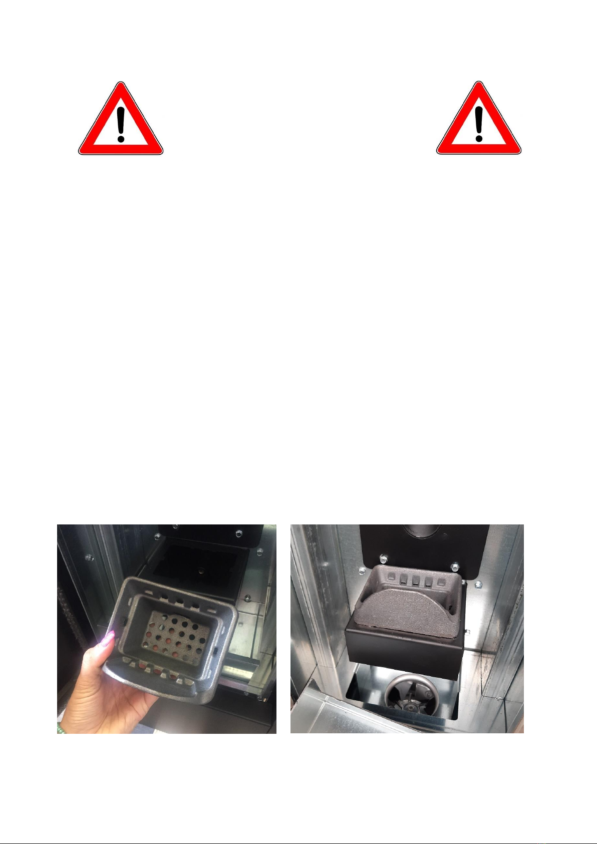
Regularly clean the burner with each ignition or with each refill of pellets.
The hearth must be kept closed, except during recharging or waste disposal, to prevent smoke from
escaping.
Do not intermittently turn the stove on and off as it is equipped with electrical and electronic components
that can be damaged.
Do not use the appliance as an incinerator or in any other way than that for which it has been designed.
Do not use liquid fuels.
Do not make any unauthorized modifications to the device.
Only use original spare parts recommended by the manufacturer...
-
-
-
-
-
-
-
-
-
-
-
-
-
-
-
-
-
-
-
-
-
-
-
-
-
-
-
-
-
-
-
7

02. GENERAL SAFETY REGULATIONS
-The fuel comes as small cylinders with a diameter of 6-7mm, a maximum length of 30mm and a maximum humidity
of 8%. The stove is manufactured and calibrated to burn pellets made up of various types of wood pressed in
compliance with regulations that protect the environment.
Switching from one type of pellet to another can result in a small variation in performance level, which
sometimes cannot even be noticed. Said variation can be solved by increasing or decreasing the power of
use in a single step.
It is important that the stove is transported in compliance with safety regulations. Imprudent movements
and blows must be avoided because they can damage the ceramics or the structure.
The metallic structure is treated with paint for high temperatures. During the first few starts, bad odors may
be released from the paint on the metal parts that dries. This does not imply any danger and it is enough to
ventilate the rooms. After the first ignitions, the paint reaches its maximum resistance and its definitive
chemical-physical characteristics.
The tank can contain up to 15 kg of pellets. To recharge it, just lift the access cover and dump the pellets, even with
the machine on, paying attention to square the tank. In the event of prolonged absences, recharge the deposit to
guarantee your autonomy.
It may happen that, if the tank is emptied, the auger is completely discharged until the machine is switched
off. To restart it and bring it to ideal conditions, it may take two starts in case the worm is particularly long.
ATTENTION! If the installation is not carried out according to the indicated procedures, in the event of a power failure, it
may produce combustion fumes in the environment.
In some cases, it may be necessary to install a continuity group.
ATTENTION! Since the stove is a heating device, it presents very hot surfaces. Precisely for this reason,
maximum caution is recommended during operation:
-
-
-
-
-
-
-
-
WITH THE STOVE ON:
either
either
either
either
either
either
either
either
The door should never be opened.
The door glass should not be touched as it is very hot. Care must
be taken that children do not come near the stove. The smoke
outlet must not be touched.
No liquid should be poured into the home.
No type of maintenance should be carried out until the stove is cold. No type
of intervention should be carried out, except by qualified personnel. All
instructions in this manual must be respected and followed.
8

03. THE SMOKE OUTLET
The flue is one of the key elements for the proper functioning of the stove. The best are those made of steel (stainless or
aluminized), due to the quality of the materials, the resistance, the duration over time, the ease of cleaning and
maintenance.
-
-
At the rear, the stove has a circular flue outlet of Φ 80mm and a terminal to which the flue must be
connected.
To facilitate the connection to the rigid steel flue, it is advisable to use telescopic unions that, in addition to
facilitating the operation, also compensate for thermal expansion of both the fireplace and the flue.
It is advisable to block the conduit to the stove terminal with silicone resistant to high temperatures (1000AC). In
the event that the mouth of the existing smoke duct is not perfectly perpendicular to the smoke outlet of the
home, the connection of these must be made with the corresponding inclined joint. The inclination, with respect to
the vertical, must never exceed 45° and must not suffer narrowing.
In case of passing through floors, it is necessary to interpose a 10 cm thick insulating sleeve.
It is absolutely necessary to insulate the flue along its entire length. The insulation allows the temperature of
the fumes to be kept high, to optimize the draft, avoid condensation and reduce the deposits of unburned
particles on the walls of the duct. To do this, use suitable insulating materials (glass wool, ceramic fiber, class
A1 incombustible materials).
The technical minimum for a correct draft of a pellet stove is 2 vertical m.
The flue must be impervious to atmospheric agents and it is necessary to avoid too many changes in
direction.
The use of flexible and extensible metal tubes is not allowed.
-
-
-
-
-
-
TILT LESS THAN 45°
CONSTRICTION
9

03. THE SMOKE OUTLET
EXISTING FLUE (TRADITIONAL)
EXTERNAL SMOKE DUCT
10

04. FINISHING OF THE CHIMNEY
The correct installation of the chimney finish allows to optimize the operation of the stove. The chimney's anti-wind
finish must be made up of such a number of elements that the sum of its section, at the outlet, is always double with
respect to that of the flue. The finish must be placed in such a way that it exceeds the ridge of the roof by
approximately 150 cm, so that it is in full wind.
Slope
of the
cover α
[°]
Horizontal width of the plaster
zone from the axis of the crest A
[m]
Minimum height of the outlet
from the ceiling Hmin
=Z+0.50m
Render zone height Z [m]
fifteen 1.85 1.00 0.50
30 1.50 1.30 0.80
Four. Five 1.30 2.00 1.50
60 1.20 2.60 2.10
eleven

05. THE SHOT
The gases that are formed during combustion, when heated, undergo an increase in volume and, therefore, assume a lower
density with respect to the cooler surrounding air.
This temperature difference between the inside and the outside of the chimney determines a depression, called
thermal depression, which is greater the higher the flue is and the higher the temperature.
The draft from the flue must be able to overcome all the resistances of the smoke circuit in such a way that the fumes
produced in the stove, during combustion, are sucked in and dispersed into the atmosphere through the exhaust
pipe and the exhaust pipe. fumes. There are several meteorological factors that influence the operation of the flue,
such as rain, fog, snow, altitude, but the most important is, without a doubt, the wind, which has the ability to cause
not only thermal depression. , but also dynamic depression.
The action of the wind varies depending on whether it is an ascending, horizontal or descending wind.
-
-
-
An upwind always has the effect of increasing the depression and therefore the draft. A horizontal
wind increases the depression in case of correct installation of the chimney cap. A descending wind
always has the effect of diminishing the depression and sometimes reverses it.
Excess draft causes overheating of the combustion and, therefore, the loss of efficiency of the stove.
Part of the combustion gases, together with small fuel particles, are sucked into the flue before being burned. This
decreases the efficiency of the stove, increases the consumption of pellets and causes the emission of polluting
fumes.
Simultaneously, the high temperature of the fuel, due to excess oxygen, wears out the combustion chamber
prematurely.
On the contrary, insufficient draft reduces combustion, cools the stove, produces smoke in the environment that
reduces the efficiency of the stove, and causes dangerous scale in the flue.
12

06. EFFICIENCY OF THE STOVE
Paradoxically, highly efficient stoves can make the job of the chimney more difficult.
The proper functioning of a fireplace depends on the increase in temperature inside it caused by the combustion
fumes.
However, the efficiency of a stove is determined by its ability to transfer most of the heat produced to the environment to be
heated. As a consequence, the more efficient the stove is, the "colder" are the residual smoke from combustion and,
therefore, the smaller the "draught".
A traditional chimney, of rough design and insulation, works much better in service than a traditional small open
fireplace or poor quality stove, where most of the heat is lost in the fumes.
Therefore, purchasing a quality stove often means having to intervene in the flue, even if it already existed and worked with
previous installations, in order to better insulate it.
If the stove does not heat or smoke, it is always due to a defective draft.
-A common mistake is to connect the stove pipe to an existing chimney, leaving the chimney still in service
from the previous installation. Thus, two solid fuel installations are connected by the same flue, which is
incorrect and dangerous. If both installations are used at the same time, the total smoke load may be
excessive for the existing section of the chimney, resulting in smoke backwash.
If only one stove is used, the heat from the fumes does cause the chimney draft, which, however, will also draw in cold air through
the opening of the extinguished installation, which cools the fumes again and blocks the draft.
Lastly, if both installations are located at different levels, in addition to the above problems, the same
principle of communicating vessels may be interfered with, which causes an irregular and unpredictable
evolution of combustion fumes.
-
-
Before installing, it is necessary to respect the following indications.
13

07. INSTALLATION INSTRUCTIONS
Choose a definitive place to place the stove and then:
-
-
-
-
Provide the connection to the flue for smoke evacuation. Provide the
outside air intake (air for combustion).
Provide the connection for the electrical line with ground discharge installation.
The electrical installation of the room where the stove is installed must be grounded; otherwise, anomalies
may occur in the dashboard.
Place the stove on the floor in a favorable position for the connection of the flue pipe and close to the "combustion
air" intake.
The appliance must be installed on a floor with adequate load capacity.
If the existing construction does not satisfy this requirement, appropriate measures must be taken (eg load
distribution plate).
It is necessary to protect from heat all structures that can catch fire if exposed to excessive heat. Wooden
floors or flammable material must be protected with non-combustible material (for example: a 4 mm sheet
or ceramic glass).
The installation of the appliance must guarantee easy access for cleaning the appliance itself, the exhaust
gas ducts and the flue.
The appliance is not suitable to be installed in a shared conduit.
During operation, the stove removes a quantity of air from the environment where it is located, therefore an
outside air intake is necessary at the height of the pipe located at the rear of the stove. The pipes to be used
for the smoke outlet must be specific pipes for pellet stoves: painted steel or stainless steel, 8 cm in
diameter, with suitable joints.
-
-
-
-
-
-
-
-The "combustion air" intake (Φ 80mm) must reach a wall facing the outside or rooms adjacent to the
installation one, as long as they have an outdoor air intake (Φ 80mm) and are not used as bedrooms or
bathrooms, or where there is a fire hazard, such as sheds, garages, combustible materials stores, etc. These
air intakes must be made in such a way that they cannot be obstructed from inside or outside and must be
protected with a grill, metal mesh or adequate protection, as long as these protections do not reduce the
minimum section.
When the stove is installed in environments surrounded by combustible materials (example: furniture, wood
paneling, etc.) the following distances must be respected:
“See stove data plate".
The installer must also consider the convective air sections during the installation: steps must be created
-
-
of air in the structure that will house the appliance.
W = 740 cm²
B = 366 cm²
14

07. INSTALLATION INSTRUCTIONS
-Although it is always advisable to respect the minimum distances and also install heat-resistant fireproof insulating panels
(rock wool, cellular cement, etc.).
The following is advised:
-Promasil 1000
-Rating temperature: 1000 °C
-Density: 245 kg/m3
-Shrinkage at reference temperature, 11 hours: 1.3/1000°C %
-Cold compressive strength: 1.4 MPa
-Flexural strength: 0.5 MPa
-Coefficient of thermal expansion: 5.4x10⁻⁶ m/mK
-Specific heat 1.03 Kj/kgK
-Thermal conductivity at an average temperature:
either 200 °C - 0.07 W/mK
either 400 °C - 0.10 W/mK
either 600 °C - 0.14 W/mK
either 800 °C - 0.17 W/mK
-Thickness: 40mm
-When the stove is on, it can create depression in the room where it is installed; therefore, other devices with
naked flame should not coexist in the room, except type c boilers (watertight).
Check the presence of combustion air. It must come from a free space (not spaces where there are
extraction fans or spaces without ventilation) or from the outside.
Do not install the stove in bedrooms or bathrooms.
-
-
INSTALLATION OF THE STOVE
In compliance with current regulations for installation, the corner stove must be located in a ventilated place where
enough air arrives to ensure proper combustion and, consequently, proper functioning. The premises must have a
volume of not less than 20 m3and to ensure correct combustion (40 m3/h of air) and a "combustion air intake" is
required that reaches a wall facing the outside or in rooms adjacent to the installation, as long as they have an
external air intake (Φ80mm) and are not used as bedrooms and bathrooms or, where there is no risk of fire, such as
sheds, garages, combustible materials stores, etc. These air intakes must be made so that they cannot be obstructed
from the inside or outside and must be protected with a grill, metal mesh or other suitable protections that do not
reduce the minimum section.
The corner stove can create depressions in the installation room; therefore, there must be no other devices with free
flame in said room (except only sealed-type boilers or unless said devices have their own air inlet).
It should not be placed near curtains, armchairs, furniture or other flammable materials.
It must not be installed in explosive atmospheres or environments that could be potentially explosive due to the presence of
machinery, materials or dust that can cause gas emissions or be easily ignited by sparks. Before installing the corner pellet
stove, check that all the finishes or possible beams of combustible material are located at a suitable distance and outside the
radiation zone of said chimney; Likewise, it must be considered that in order not to impair the proper functioning of the
appliance, it is essential to create a recirculation of the air inside it.
ATTENTION: The stoves must be installed with a draft of at least 2 meters of pipe with a diameter of 80 mm and certified according to
the EN 1856-2 standard.
fifteen

07. INSTALLATION INSTRUCTIONS
INSTALLATION EXAMPLE:
EXAMPLE OF INCORRECT INSTALLATION:
Never install the smoke evacuation pipes so that the evacuation gases exit through a straight horizontal outlet or
directed downwards.
16

08. MICRONOVA N100 ELECTRONICS WITH 3-BUTTON LED DISPLAY
8.1 Correct operation and control regulation devices
8.1.1 Console
The console allows easy dialogue with the controller by pressing a few buttons. A display and indicators with LEDs
inform the operator about the operating status of the stove. In programming mode, the various parameters are
displayed.ros modifiable with the buttons is.
Chrono LED Status/power/parameter display
LED set power LED ON/OFF
ambient LED set
OFF
P1 Pushbutton
decrease/menu/set
ambient
P3 ON/OFF/ button
exit/confirmation
P2 Increase button/
stove status/set
power
auger screw led/
exchanger-pump/
spark plug
alarm LED
8.1.2 Meaning of the LEDs
leds meaning on
AMBIANCE SET
Ambient set programming
SET POWER
Power set programming
CHRONO
chrono enabled
ALARM
stove in alarm
SPARK PLUG
spark plug
ENDLESS SCREW
moving auger
EXCHANGER - PUMP
Exchanger / pump on
ON\OFF
work status
display
display function conditions display
OFF OFF+AMBIENT TEMPERATURE
Condition
power
ON ON+ROOM TEMPERATURE
DISPLAY LOAD PELLET LOADING
Name
parameter
TEMPERATURE
AMBIENT+POWER
WORK+HOUR
WORKED
PROGRAMMING SELECTED PARAMETER
17

8. MICRONOVA N100 ELECTRONICS WITH 3-BUTTON LED DISPLAY
8.2 The menu
A long press on button P1 enters the menu.
Said menu is divided into several options and levels to access the settings and programming of the card.
8.2.1 User menu
The following table synthetically describes the menu structure; This paragraph only covers the selections available to
the user.
level 1 Level 2 level 3 worth
M1 –clock set -
Weekday LMMJVSD
clock hours 0-23
minutes clock 0-59
day clock 1-31
month clock 1-11
clock year 00-99
M2 –set chrono
M2-1 – enable chrono
01 – enable chrono on/off
M2-2 – daily schedule
01 – day chrono on/off
02 - start 1 day OFF-0-23:50
03 - stop 1 day OFF-0-23:50
04 - start 2 day OFF-0-23:50
05 - stop 2 day OFF-0-23:50
M2-3 – weekly programming
01 – weekly programming on/off
02 - start Prg 1 OFF-0-23:50
03 - stop Prg 1 OFF-0-23:50
04 – Monday Prg1 on/off
05 - Tuesday Prg 1 on/off
06 - Wednesday Prg 1 on/off
07 - Thursday Prg1 on/off
08 - Friday Prg 1 on/off
09 - Saturday Prg 1 on/off
10 - Sunday Prg 1 on/off
11 - start Prg 2 OFF-0-23:50
11 - stop Prg 2 OFF-0-23:50
13 - Monday Prg2 on/off
14 - Tuesday Prg 2 on/off
15 - Wednesday Prg 2 on/off
16 - Thursday Prg 2 on/off
17 - Friday Prg 2 on/off
18 - Saturday Prg 2 on/off
19 - Sunday Prg 2 on/off
20 - start Prg 3 OFF-0-23:50
21 - stop Prg 3 OFF-0-23:50
22 - Monday Prg 3 on/off
23 - Tuesday Prg 3 on/off
24 - Wednesday Prg 3 on/off
25 - Thursday Prg 3 on/off
26 - Friday Prg 3 on/off
27 - Saturday Prg 3 on/off
28 - Sunday Prg 3 on/off
29 - start Prg 4 OFF-0-23:50
30 - stop Prg 4 OFF-0-23:50
31 - Monday Prg 4 on/off
32 - Tuesday Prg 4 on/off
33 - Wednesday Prg 4 on/off
34 - Thursday Prg 4 on/off
35 - Friday Prg 4 on/off
36 - Saturday Prg 4 on/off
37 - Sunday Prg 4 on/off
18

8. MICRONOVA N100 ELECTRONICS WITH 3-BUTTON LED DISPLAY
M2-4 – weekend programming
01 – weekend timer on/off
02 - start weekend 1 OFF-0-23:50
03 - stop weekend 1 OFF-0-23:50
04 - start weekend 2 OFF-0-23:50
05 - stop weekend 2 OFF-0-23:50
M2-5 - exit set
M3 – language
selection
01 – Italian set
02 – English set
03 – French set
03 - German set
M4 - standby
01 -stand-by on/off
MS– Buzzer
01 – buzzer on/off
M6 – Initial Charge
01 – initial charge 90”
M7 – Stove status
01 – stove status
01 – Worm screw state info
02 – T minutes info
03 – Thermostat status info
04 – Smoke status info
05 – State of smoke extractor
revolutions rpm info
M8
technical
– Calibrations
01 - Password set
M9 – Exit
01 - Exit set
8.2.2 Menu M1 – Set clock
It is used to set the current time and date. The card has a lithium battery with an autonomy of more than 3/5 years
for the clock.
Press the P1 button for two seconds to access the general programming menu. Pressing P1 (decrease) or P2 (increase)
selects the M1 option and the "M1 set orologio" scrolling message appears.
(figure 13a)
ME
Figure 13a
MON
Figure 13b
19

08. MICRONOVA N100 ELECTRONICS WITH 3-BUTTON LED DISPLAY
Choose a day and press button P3
(figure 13b),
time adjustment occurs (
figure 13c
), of the minutes (
figure 13d
), of the day (
figure 13e
), of the month (
figure 13f
) and of the year (
figure 13g
) using pushbuttons P1 (decrease) and P2 (increase) and
confirm with pushbutton P3.
PRAY
MIN
GIO
MONTH
ANN
twenty
Table of contents
Popular Stove manuals by other brands

Ravelli
Ravelli HRV 200 instructions

Blaze King
Blaze King CHINOOK CK20.2 Operation & installation manual

England's Stove Works
England's Stove Works 24-JC Installation and operation manual

Thermo Pride
Thermo Pride OL11-105FDBE Operation manual

Wamsler
Wamsler K 118 Instructions for installation and use

lifelong
lifelong LLHT904 user manual

Desa
Desa Comfort Glow S26NT OWNER'S OPERATION AND INSTALLATION MANUAL

Westfire
Westfire Uniq 44 Installation manual and operating instructions

Harvia
Harvia M3 SL Instructions for installation

USSC
USSC Golden eagle 5520 owner's manual

Sierra Products
Sierra Products Woodstove Specifications

Varmebaronen
Varmebaronen Vedolux 350 Installation and Maintenance