EiE INSTRUMENTS PT-115TAT15 User manual
www.eieinstruments.com, www.eiepharmatest.com, www.eieceratest.com, www.eiepetrotest.com
B-14, Zaveri Industrial Estate, Opp. Shyam-Villa Society, Near Saraswati Vidhyalaya, Kathwada
GIDC road, Near Singarva Bus Stand, Off. National Highway, Ahmedabad –382430, Gujarat, India
Telephone: +91-79-66040613, +91-79-66040600
Product Manual EIE –PT-115TAT15/30 –Universal Testing Machine

EIE INSTRUMENTS PVT LTD
Operation & Maintenance Instruction Manual
Equipment Name: Universal Testing Machine (Adhesive)
Equipment Serial Number:
Document Number: EIE/OM/UTMA/01
Page No.: 2 of 21
Organization’s ISO 9001:2015 Certificate

EIE INSTRUMENTS PVT LTD
Operation & Maintenance Instruction Manual
Equipment Name: Universal Testing Machine (Adhesive)
Equipment Serial Number:
Document Number: EIE/OM/UTMA/01
Page No.: 3 of 21
Forward
Dear valued customer,
We are thankful of you for your keen interest in our company products. We hope you enjoy
using them and find them to be helpful and reliable. We greatly appreciate your business
and the opportunity you have provided us to assist you. You have joined a selected group
of customers who have switched to the technologically superior and quality enhanced
laboratory testing products.
Time has changed, so does the technology. Your purchase lists you on the cutting edge of
the 21st century technology. To help you get the most out of your EIE Instruments Pvt. Ltd.
products, we have created this instruction manual that is an excellent way of expressing
and maintaining your trust in EIE’s - superior quality testing products. Our continued efforts
and commitment are to provide you with the best and efficient services after sales, prompt
attention and the highest level of customer satisfaction. If for any reasons, you have
questions or comments, we are delighted to hear from you. We welcome your feedback for
further improvement in our product(s). We would be happy to help you in any way we can.
You can contact us on +91-9909903582 or send us an email at
your call or email within 24-48 working hours.
Once again, we would like to thank you for your trust and kind patronage. We look forward
to serve you better in the future.
Yours sincerely,
EIE Instruments Private Limited

EIE INSTRUMENTS PVT LTD
Operation & Maintenance Instruction Manual
Equipment Name: Universal Testing Machine (Adhesive)
Equipment Serial Number:
Document Number: EIE/OM/UTMA/01
Page No.: 4 of 21
Table of Contents
Organization’s ISO 9001:2015 Certificate...............................................................................................2
Forward...................................................................................................................................................3
Table of Contents....................................................................................................................................4
Table of Figures.......................................................................................................................................5
List of Tables ...........................................................................................................................................5
1 Introduction to EIE –Universal Testing Machine...........................................................................6
1.1 General Product Descriptions.................................................................................................6
1.2 Terminology ............................................................................................................................6
1.2.1 Tensile Test .....................................................................................................................6
1.2.2 Shear Test........................................................................................................................6
1.2.3 Compression Test............................................................................................................6
2 Technical Specification...................................................................................................................7
2.1 Introduction to EIE –Universal Testing Machine....................................................................7
3 Safety..............................................................................................................................................7
3.1 Safety Instructions ..................................................................................................................8
4 Installation of Universal Testing Machine (UTM)...........................................................................9
4.1 Component Diagram of Universal Testing Machine (Digital Controller Based) ...................10
4.2 Electrical Circuit Diagram of Universal Testing Machine......................................................11
5 Introduction to Digital Controller of Universal Testing Machine.................................................12
5.1 Operating Instruction of Digital Controller...........................................................................12
5.2 Speed Setting Process...........................................................................................................14
6 Standard Operation Procedure....................................................................................................15
6.1 Determination of Tensile Adhesive Strength........................................................................15
6.2 Determination of Shear Adhesive Strength..........................................................................16
6.3 Deformation Test..................................................................................................................17
7 Precautions to Followed...............................................................................................................18

EIE INSTRUMENTS PVT LTD
Operation & Maintenance Instruction Manual
Equipment Name: Universal Testing Machine (Adhesive)
Equipment Serial Number:
Document Number: EIE/OM/UTMA/01
Page No.: 5 of 21
Warranty Certificate .............................................................................................................................20
Table of Figures
Figure 1 Component Diagram of UTM..................................................................................................10
Figure 2 Circuit Diagram of UTM ..........................................................................................................11
Figure 3 Home screen ...........................................................................................................................13
Figure 4 Auto rev. function ...................................................................................................................13
Figure 5 Test Selection window ............................................................................................................14
Figure 6 setting window........................................................................................................................14
Figure 7 Speed checking screen............................................................................................................14
Figure 8 Test Grip for Tensile Adhesive test .........................................................................................15
Figure 9 Tensile test speed screen........................................................................................................15
Figure 10 Test grip for Shear adhesive test ..........................................................................................16
Figure 11 Deformation test assembling................................................................................................17
List of Tables
Table 1 UTM Functional Keys................................................................................................................12

EIE INSTRUMENTS PVT LTD
Operation & Maintenance Instruction Manual
Equipment Name: Universal Testing Machine (Adhesive)
Equipment Serial Number:
Document Number: EIE/OM/UTMA/01
Page No.: 6 of 21
1Introduction to EIE –Universal Testing Machine
EIE –Universal Testing Machine (UTM) is also known as universal tester, material testing machine or
materials test frame. It is the most fundamental materials science and engineering tests that you can
perform on any material. This test is performed on the material to determine how much tension,
strain, compression etc. a material can handle; it also determines the breaking strength of the
material. Many other properties that are measured by the Universal testing machine.
1.1 General Product Descriptions
EIE –Universal Testing Machine (UTM) is a benchtop model capable of performing tension,
compression, shear and Flexure Tests. The unit consists of two load cells (i.e. 3000kg for Tensile/
Compression Test and 500 kg for Flexural (deformation) Test). Loading is accomplished by the lower
crosshead (acting plate) being driven by double screw powered by an electronically controlled servo
drive motor. Hard chrome plated columns maintain alignment of the crossheads.
Operation of the UTM is controlled by Digital Controller. A variety of accessories are available to
provide added capability and flexibility as per test requirements. These include furnaces, ovens, Grips,
fixtures and data acquisition etc. (On extra cost).
1.2 Terminology
1.2.1 Tensile Test
Tensile test is performed to determine the effectiveness and behaviour of a material when a stretching
force acts on it.
1.2.2 Shear Test
Shear testing is performed to determine the shear strength of a material. It measures the maximum
shear stress that may be sustained before a material will rupture. Shear testing is commonly used with
adhesives and can be used in either a tensile or comprehensive method.
1.2.3 Compression Test
Compression test is the test in which a material experiences opposing forces that push inward upon
the specimen from opposite sides or is otherwise compressed, “squashed”, crushed, or flattened.

EIE INSTRUMENTS PVT LTD
Operation & Maintenance Instruction Manual
Equipment Name: Universal Testing Machine (Adhesive)
Equipment Serial Number:
Document Number: EIE/OM/UTMA/01
Page No.: 7 of 21
2Technical Specification
Capacity : Load Cell 1: 3000 KG & Load Cell 2: 500 KG
Speed Range : 0 –500 mm/minute.
Motor : Three Phases, Voltage 440 Volt AC
Drive : 440 V, 3 Phase input, 3 Phase output
Salzer Switch : Mains ON/OFF Switch
Emergency Switch: To prevent load cell and accessories (Emergency stop to prevent any damage)
2.1 Introduction to EIE –Universal Testing Machine
Parts of Universal Testing Machine –Digital Controller
Structure: Components and parts are fabricated from high grade stainless steel/mild steel
material, which are hard chrome plated, wherever required and Powder coated in
attractive shades.
Motor: Electrical motor for speed variation between range of 0.001-500 mm/min.
Gear: Gear is fitted for altering the RPM of motor respectively as per test requirement.
Pulley: Pulley is fitted to maintain ratio of max.& min. speed requirement of machine
Two Tie Rods: To support movement of middle plate up and down with fine guide
Double Screw: To drive and support up/down movement of middle acting plate
Top Plate: Acts as support for mounting the load cells/Stationary grip
Base Plate: Acts as support for mounting the Load cells/Stationary grip.
Grip Jaw: It is used to clamp test specimen (According to specific test)
Control Panel: Controlling accessories for operating the machine.
Limit switch: To prevent the moving crossheads from exceeding the pre –set range.
Instrument: Load and extension/compression data transfer module.
3Safety
All EIE equipment is designed to be operated with the highest level of safety. This manual use
note, caution and warning symbols throughout to draw your attention to important operational
and safety information.
Read and follow these important instructions. Failure to observe these instructions can result in
permanent damage to the unit, significant property damage, personal injury.
EIE INSTRUMENTS PVT LTD
Operation & Maintenance Instruction Manual
Equipment Name: Universal Testing Machine (Adhesive)
Equipment Serial Number:
Document Number: EIE/OM/UTMA/01
Page No.: 8 of 21
3.1 Safety Instructions
Read and understand all instructions and safety precautions listed in this manual before
installing or operating your unit. If you have any questions regarding operation of the unit
or instructions in this manual, contact our service Department.
Thoroughly understand the safety features and operation of the equipment. This manual
will provide operators with safety concerns and general procedures. Be familiar with
correct operating principals and use good judgement. Also refer to the appropriate
manuals for system component safety instruction manuals.
Obey all national and local electric code requirements.
Dangerous high voltages present. Do not attempt to open the enclosure or gain to areas
where you are not instructed to do so. Refer servicing to qualified service personnel only.

EIE INSTRUMENTS PVT LTD
Operation & Maintenance Instruction Manual
Equipment Name: Universal Testing Machine (Adhesive)
Equipment Serial Number:
Document Number: EIE/OM/UTMA/01
Page No.: 9 of 21
4Installation of Universal Testing Machine (UTM)
1. Remove the shipping crate and packing material immediately upon receipt. Inspect for any sign of
damage incurred during shipment. If any damage found, immediately discuss it with the delivery
person and contact to transport company immediately. Also make notes of any damages on the
bill of landing.
2. Retain all shipping material for later inspection.
3. Check packing slip carefully and ensure all materials have been received as indicated in packing
slip.
4. Please, inspect and note whether any part of the instrument or any accessory is missing according
to packing slip? If it is so, then immediately make note of it and report to the manufacturer.
5. Due to the vibration incurred during shipping and handling, it is possible that mechanical
connection could become loose. Inspect all connection to ensure that they are secure.
6. After visual inspection, if everything is found to be okay, transit the instrument to suitable safe
place where it is intended to install. Caution: Handle with care.
7. Lift the instrument from the shipping pallet by lifting under the base or the upper crosshead. Do
not lift the by loading (lower) crosshead. If using a fork lift, make sure the forks are fully supporting
the front and back of the base otherwise damage may occur to components under the base.
8. Recycle the packing material. Do not throw it away for environment protection.
9. Place the unit on a plain, even and sturdy surface leaving 12-18” space away from the wall.
10. Do not install unit in a corrosive environment. A corrosive environment may lead to poor
performance and deterioration of unit.
11. Do not place the equipment in a draft, sunlight or near a place of equipment, which emits heat as
well as electromagnetic conduction emission.
12. Keep the standard operating procedure and the respective standard handy to conduct the test.
EIE INSTRUMENTS PVT LTD
Operation & Maintenance Instruction Manual
Equipment Name: Universal Testing Machine (Adhesive)
Equipment Serial Number:
Document Number: EIE/OM/UTMA/01
Page No.: 10 of 21
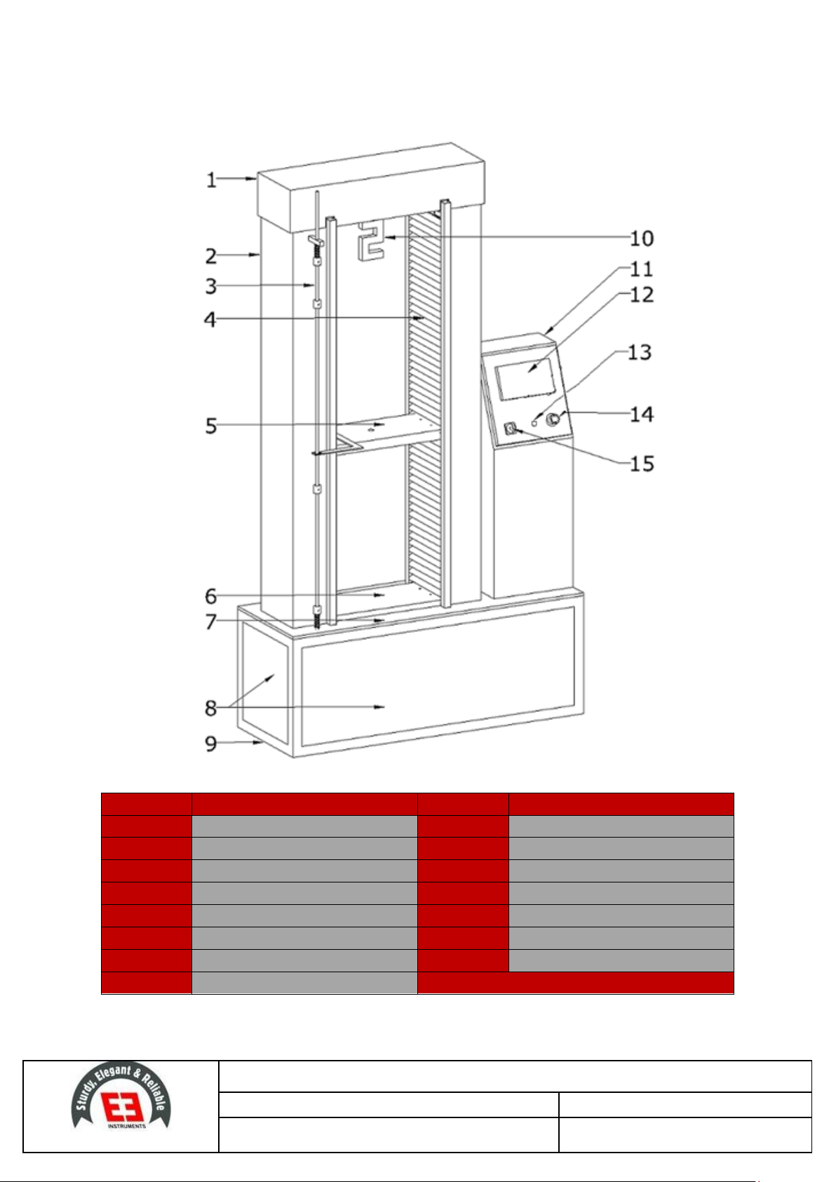
4.1 Component Diagram of Universal Testing Machine (Digital Controller Based)
ID
DESCRIPTION
ID
DESCRIPTION
1
Casing for Timing Pulley and Belt
9
Angle Structure
2
Casing For Guide Rod & Screw
10
Load Cell
3
Limit switch Unit
11
Control Panel
4
Chip cover
12
Digital Controller (Load Indicator)
5
Movable (acting) Plate
13
Emergency switch
6
Bottom Plate
14
Mains Indicator
7
Base sheet (Body)
15
Mains Switch
8
Side & front Body Covers
Figure 1 Component Diagram of UTM

EIE INSTRUMENTS PVT LTD
Operation & Maintenance Instruction Manual
Equipment Name: Universal Testing Machine (Adhesive)
Equipment Serial Number:
Document Number: EIE/OM/UTMA/01
Page No.: 11 of 21
4.2 Electrical Circuit Diagram of Universal Testing Machine
Figure 2 Circuit Diagram of UTM
EIE INSTRUMENTS PVT LTD
Operation & Maintenance Instruction Manual
Equipment Name: Universal Testing Machine (Adhesive)
Equipment Serial Number:
Document Number: EIE/OM/UTMA/01
Page No.: 12 of 21
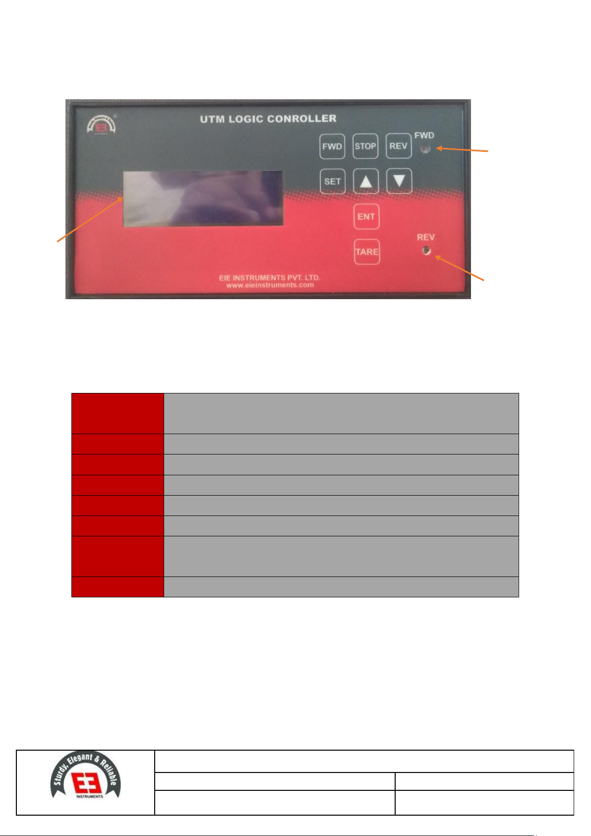
5Introduction to Digital Controller of Universal Testing Machine
1: FWD Indicator –Glows when the acting plate is moving in Forward mode.
2: REV Indicator –Glows when the acting plate is moving in reverse mode.
3: Display
Functioning Keys of Digital Controller
FWD
To move the acting plate in forward direction (i.e. Downward/Upward
direction depends on test type selected mode)
STOP
To stop the functioning of acting plate.
REV
To move the acting plate in reverse direction.
SET
To enter in parameter setting mode.
UP KEY
To Increase parameter values in set mode.
DOWN KEY
To decrease parameter values in set mode.
ENTER KEY
To confirm/save changed parameter values in setting mode. It is also used to
return back to home screen window from set mode.
TARE
To nullify the load value which occurs before starting actual test process.
Table 1 UTM Functional Keys
5.1 Operating Instruction of Digital Controller
Plug the mains power chord to the respective 3 –pin socket (440 volts 50 Hz three phase).
Turn “ON” the main switch (Salzer) mounted on the control panel of the unit.
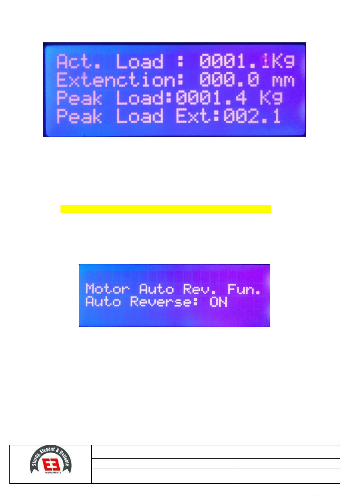
Display of the control glows, indicating that the unit is in functioning mode, displaying following
parameters as shown in figure: 3.
3
1
2
EIE INSTRUMENTS PVT LTD
Operation & Maintenance Instruction Manual
Equipment Name: Universal Testing Machine (Adhesive)
Equipment Serial Number:
Document Number: EIE/OM/UTMA/01
Page No.: 13 of 21
Figure 3 Home screen
Actual Load : It indicates actual load being applied on the sample during test process. (In KG)
Elongation : It indicates the travelling distance of the moving platen. (In MM)
Peak Load : It indicates the maximum load at which sample fails/ruptures.
Peak Load ext. : It indicates the distance at which at which sample tears completely.
NOTE: Actual result will be indicated after the completion of test or failure of sample.
Before processing for the actual test process, follow few steps as explained below:
Press & hold “SET” button for 2 seconds, to enter in set mode. immediately auto reverse
function window will open, showing current status of the function, i.e. “ON”, as shown in the
figure 4.
Figure 4 Auto rev. function
User can turn it ON/OFF using UP/DOWN button respectively. (Recommended to turn it ON
always)
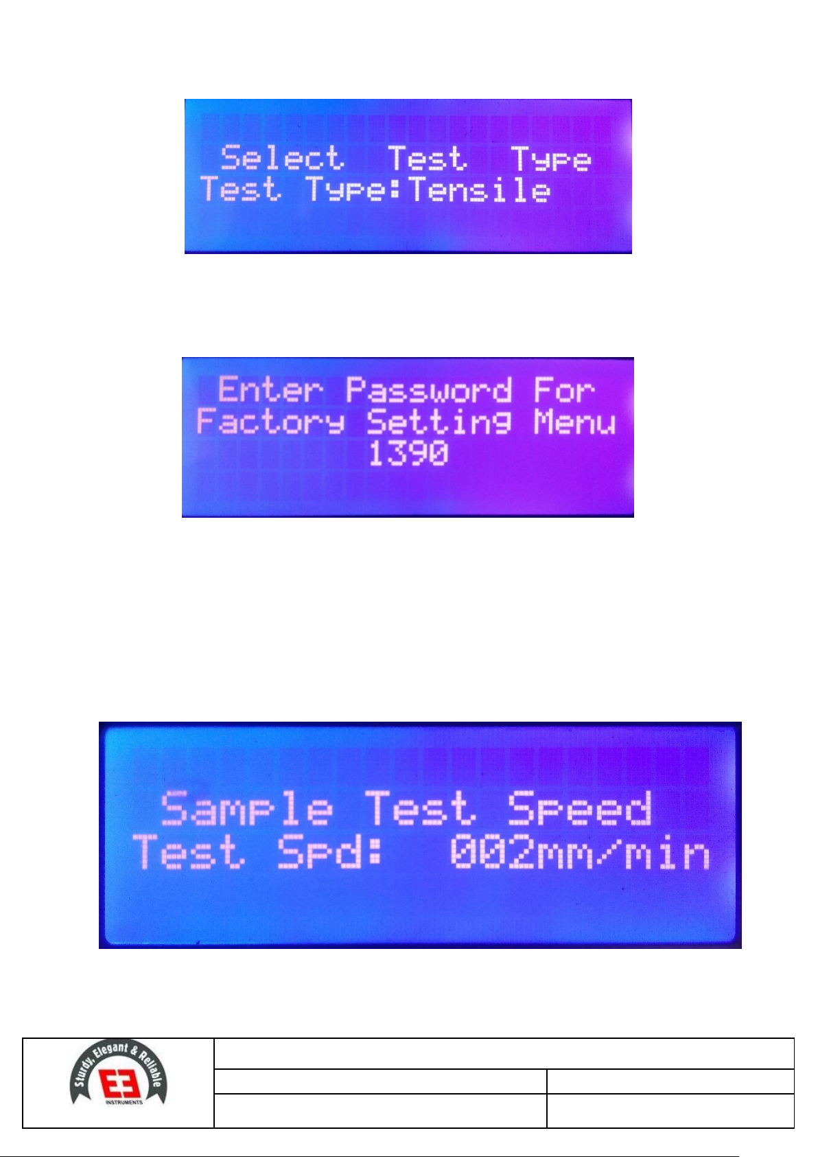
Again have a long Press on “SET” button, test selection window will open as shown in figure: 5.
select test type as per preparation and need of test (i.e. TENSILE/COMPRESSION/FLEXURAL). User
can scroll different test type using “UP & DOWN” button and then press “ENTER” button to select
the test type.
EIE INSTRUMENTS PVT LTD
Operation & Maintenance Instruction Manual
Equipment Name: Universal Testing Machine (Adhesive)
Equipment Serial Number:
Document Number: EIE/OM/UTMA/01
Page No.: 14 of 21
Figure 5 Test Selection window
By pressing “SET” three times, Factory setting window open, which is password protected, an
authorized person is only permitted to use this window. (Caution: Do not alter these settings)
Figure 6 setting window
This is used for calibration and other important settings.
NOTE: “FACTORY SET” settings, do not need any changes.
5.2 Speed Setting Process
Press & hold “SET” button for 2 – 3 seconds, to enter in set mode, scroll using set button until the
screen displays the sample test speed on the screen as shown in figure: 7.
Figure 7 Speed checking screen
Now using “UP & DOWN” arrow buttons, increase/decrease the speed of test respectively.

EIE INSTRUMENTS PVT LTD
Operation & Maintenance Instruction Manual
Equipment Name: Universal Testing Machine (Adhesive)
Equipment Serial Number:
Document Number: EIE/OM/UTMA/01
Page No.: 15 of 21
6Standard Operation Procedure
6.1 Determination of Tensile Adhesive Strength
Prepare five test piece of tiles of size (50 mm ± 1 mm 50 mm ± 1 mm 6mm) according to IS
15477.
Mount the hook type grip (jaws) to Load cell 1 (i.e. 3000 KG) which is mounted on top crosshead.
Figure 8 Test Grip for Tensile Adhesive test
Remove the test unit from conditioning environment and insert it in the test unit holder mounted
in tensile testing machine and it must be centrally clamped. (It is recommended to use vice for
adjustment and better accuracy)
Select the test type to “TENSILE” from test type selection mode (as explained in figure: 5), press
enter button after selecting tensile test, following window will open as shown in figure:
Figure 9 Tensile test speed screen
For tensile adhesive test, set the speed of test i.e. 250 N/min (25 kg/sec) is factory set for Tensile
Adhesive Test as per standard) as per prescribed in standard.
TARE the load to (000.0) on the instrument display (if any load is recorded while placing the
sample or during adjustment) using “TARE” button.
Now start the test by pressing “FWD” button, immediately acting plate will start moving in
forward direction (downward direction).

EIE INSTRUMENTS PVT LTD
Operation & Maintenance Instruction Manual
Equipment Name: Universal Testing Machine (Adhesive)
Equipment Serial Number:
Document Number: EIE/OM/UTMA/01
Page No.: 16 of 21
Note the tensile adhesion strength of the test unit. Then test each of the other test units similarly.
If one or both of the tiles in any test unit are broken in the test, Record the value at which the
breakage occurred. (Include it in mean calculation)
After failure/ rupture of sample, machine will auto reverse to its original position.
NOTE: Be careful during the process, if acting plate not stops automatically after reaching to its
original position, stop the machine using “STOP” button or Emergency switch.
If the value is within ± 15 percent of the mean value, discard any individual result in which the
breaking force differs by more than 15 percent from the mean value.
6.2 Determination of Shear Adhesive Strength
Place 108 mm108 mm6.5 mm test piece tile on a plane horizontal surface and locate the jig
over the tile and against one corner of it.
Replace the grips as per test, which is supplied with the machine, mount the grip in acting plate
tightly and compressing head to the load cell 1. (as shown in figure: 10)
Figure 10 Test grip for Shear adhesive test
Remove the test unit from conditioning, insert it into the test unit holder mounted in the
Universal testing machine.
Fix the sample centrally with respect to the compressing head, tight the sample using the slider
and lock it using the knob. Caution: Do not apply high force, as it may damage the sample
Select the test type to “COMPRESSION” from test type selection mode (as explained in figure: 5)
After that Set the test speed of the cross –head (acting plate) to 5 mm/ minute.
TARE the load to (000.0) on the instrument display (if any load is recorded while placing the
sample or during adjustment) using “TARE” button.

EIE INSTRUMENTS PVT LTD
Operation & Maintenance Instruction Manual
Equipment Name: Universal Testing Machine (Adhesive)
Equipment Serial Number:
Document Number: EIE/OM/UTMA/01
Page No.: 17 of 21
Now start the test by pressing “FWD” button, immediately acting plate will start moving in
forward direction (Upward direction).
Failure of the unit shall be deemed to have occurred when the applied force reaches a maximum
value.
Then test each of the other test units similarly.
If one or both of the test tiles are broken in the test, record the value at which breakage occurs,
and include it in the mean shear adhesion strength calculation,
After failure/ rupture of sample, machine will auto reverse to its original position.
NOTE: Be careful during the process, if acting plate not stops automatically after reaching to its original
position, stop the machine using “STOP” button or Emergency switch.
If the value is within ± 15 percent of the mean value, discard any individual result in which the
breaking force differs by more than 15 percent from the mean value.
6.3 Deformation Test
For deformation test user needs, to do respective changes as explained below:
Mount LOAD CELL 2 (500 KG) in the lower end of the Load Cell 1 and clamp the anvil to the load
cell2 tightly.
After that place the Test Jig (supporting span) on the moving crosshead (acting plate) of the
machine. (as shown in figure: 11)
Figure 11 Deformation test assembling
Mark a centre point on the Anvil circumference, to adjust the test jig assembly and laser sensor
centrally.
NOTE: Adjust the laser sensor light carefully, as it is very precise and its affects test accuracy.
Prepare the sample of 300 ± 1 mm 45± 1 mm 3 ± 0.005 mm, according to IS 15477.

EIE INSTRUMENTS PVT LTD
Operation & Maintenance Instruction Manual
Equipment Name: Universal Testing Machine (Adhesive)
Equipment Serial Number:
Document Number: EIE/OM/UTMA/01
Page No.: 18 of 21
Place test piece on supporting rod of Test jig horizontally, and check the beam of laser light, it
must be in centre of the sample.
Select the test type to “FLEXURAL” from test type selection mode (as explained in figure: 5)
After that Set the test speed of the cross –head (acting plate) to 2 mm/ minute.
TARE the load of “DEFORMATION” to (000.0) on the display using “UP ARROW” button (to nullify
the deflection recorded while placing the sample or during adjustment).
Now start the test by pressing “FWD” button, immediately acting plate will start moving in
forward direction (Upward direction).
Failure of the unit shall be deemed to have occurred when the applied force reaches a maximum
value.
Then test each of the other test units similarly.
If one or both of the test samples are broken in the test, record the value at which breakage
occurs, and include it in the mean deformation strength calculation,
After failure/ rupture of sample, machine will auto reverse to its original position.
NOTE: Be careful during the process, if acting plate not stops automatically after reaching to its
original position, stop the machine using “STOP” button or Emergency switch.
7Precautions to Followed
The following statements are CAUTION statements. These statements alert the operator to conditions
that may damage equipment. Operators must be aware of these conditions to ensure safe operation
of this equipment.
1) Set the adjustable limit switches prior to test operation. The limit switches prevent the moving
crosshead (acting plate) from exceeding the pre-set range. Set the limit switches just above and
below the range set for the moving crosshead.
2) If necessary, stop test operation in case of emergency. Use the emergency Stop button on the
UTM to abort test operation.
3) Do not exceed the rated capacity of the adapter, grips, or load cell.
4) Do not lift the UTM by its loading crosshead or it may damage the machine. Lift only under the
housing or by the adjustable crosshead.
5) Be sure the correct load cell in use is selected in the load cell configuration menu.
6) Test capacity is determined by the smallest load cell in a load train regardless of which cell is
connected. If higher capacity is needed, switch as explained.

EIE INSTRUMENTS PVT LTD
Operation & Maintenance Instruction Manual
Equipment Name: Universal Testing Machine (Adhesive)
Equipment Serial Number:
Document Number: EIE/OM/UTMA/01
Page No.: 19 of 21
7) Observe maximum temperature ratings of test Components (extensometer, grips, fixtures,
couplings, etc.)
8) Avoid ramming grips and fixtures together at high speeds. The load cell protection feature may
not react fast enough to avoid damage to load cell.
9) While cleaning take care that the small/ sensitive parts do not get damaged.
10) Keep the instrument tidy, clean and dry with mint cream. Before initiating the fresh day, use
preferably clean soft cloth. Brush up the unit body as to maintain its finishing and shine.
11) Place the unit in plane and even surface only, otherwise inaccuracy may occur.
12) Mount respective set of the jaws carefully and must be fitted tightly.
13) Always connect to 440 volts, 3 phase, AC supply and in proper grounded outlet to prevent electric
shocks.
14) After completion of test remove the test units and tiles from the instrument.
15) Disassembly of this equipment is strictly limited to the qualified persons and licensed engineers
only.
16) In case of any difficulty, please do not try to repair without consulting the manufacturer,
especially when the instrument is under the warranty period.

EIE INSTRUMENTS PVT LTD
Operation & Maintenance Instruction Manual
Equipment Name: Universal Testing Machine (Adhesive)
Equipment Serial Number:
Document Number: EIE/OM/UTMA/01
Page No.: 20 of 21
Warranty Certificate
Your EIE product is guaranteed to be free from defects in materials and workmanship for one (1) year under
normal use from the date of purchase. This warranty does not apply to any product damaged by accident,
misuse, mishandling, abuse, negligence, transit, improper line voltage, drop, fire, flood or if the products were
altered or repaired by anyone other than the qualified service personnel. The liability of EIE Instruments is
limited to repair or replacement and under no circumstances shall EIE be liable for any collateral consequential
damages or loss. This guarantee specifically excludes the expendables and consumables. All warranty claims
must be directed to your corresponding purchase organization that is responsible for the sale of this equipment.
The users are responsible for shipping expense. The warranty cards which are not signed and stamped by the
actual user will be treated as void. The warranty card should accompany the defective products sent for repair,
without which no claims would be entertained. Please detach the below warranty card from following cut-line.
………………………………………………………………………………………………………………………………………
Attributes
Details
Name of the Company
Address
Telephone Number
Mobile Number
Email Address
Date of Purchase
Product Model
Serial Number
Bill or Cash Memo Number
This card should be detached, filled in properly and posted within 15 days from the date of purchase
otherwise the warranty becomes invalid.
This manual suits for next models
1
Table of contents
Other EiE INSTRUMENTS Test Equipment manuals


