IM MY40-02EN <P 2>
<Deleting data>
Data saved can be collectively deleted.
(1) Turnthefunctionswitchfrompower-offtothecontinuitytestposition(Clr)while
pressing and holding the key(MEM).
(2) “MEM”and“CLr”appear.
(3) Pressthe key(MEM).“CLr”startsashing.
(4) Pressthe key(MEM)againwhile“CLr”isashing.
Thebuzzersoundsandalldataaredeleted(donotchangethepositionof
thefunctiondialfortwosecondswhen“CLr”isdisplayed).
The tester changes its mode to measurement of conductor resistances.
To stop deleting of data:
Do not perform any key operation and wait for 10 seconds while
the“CLr”indicationmentionedinstep(3)isashing;or
Turn the function switch to another rating.
<Turning off the memory feature>
Turn the function switch to the off position.
14.8 Comparator
When a measured insulation resistance is less than the reference value setting,
the markappearsandthebuzzersounds.Alsothemeasuredvalueis
automatically held for 5 seconds.
<Selecting the reference value>
Selectfromthreepresetvaluesforeachrating.
Defaultvalues:no.01:0.1MΩ/no.02:0.2MΩ/no.03:0.4MΩ
(1) Turnthefunctionswitchtoameasurementrating.
(2) Pressthe key.
(3) “ ”appears and the reference value appears on the subdisplay.
(4) Pressingthe key(Select)changesthereferencevaluedisplayasfollows.
0.1MΩ→0.2MΩ→0.4MΩ→Comparatoroff(nodisplay)
The reference value currently displayed is selected as the comparator setting.
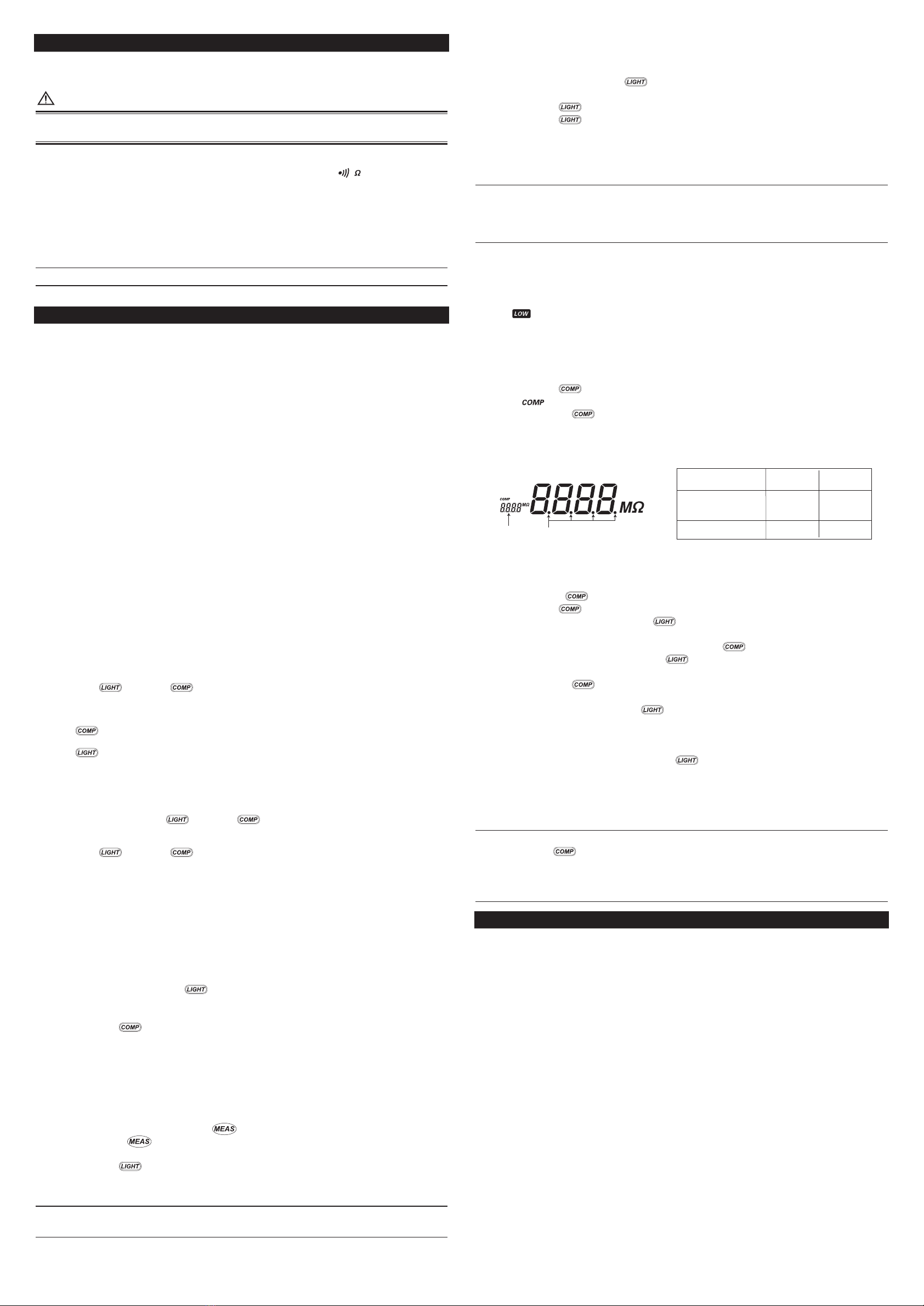
<Setting the preset values>
Position of decimal point
Measured
value
Reference
Reference
value
no.
Maine
display Sub-
display
Comparator setting
Insulation resistance
measurement
(with comparator)
<Setting the preset values>
Eachofthedefaultpresetvaluesno.01tono.03canbechangedindependently.
(1) Turnthefunctionswitchfrompower-offtoadesiredratingwhilepressingand
holding the key.“no.01”onthesub-displayashes.
Pressthe key(Select)toselectno.02orno.03.
(2) Conrmthesettingno.withthe key(Enter).
The reference value on the main display can be set.
(3) Selectthepositionofthedecimalpointwiththe key(Select).
(4) Conrmthedecimalpointwiththe key(Enter).
(5) Selectthenumberforeachdigitsequentially.
Pressingthe key(Select)changesthenumberasfollows.
0→1→2···8→9→0
(6) Conrmthenumberwiththe key(Enter).
(7) Setthenumberforthenextdigit.
(8) Whensettingsforallthedigitsarecomplete,
thereferencevaluestartsashing.
(9) Conrmthereferencevaluewiththe key(Enter).
Thebuzzersoundsandthesettingends.
The tester changes its mode to measurement of insulation resistances.
Repeatsteps(1)to(9)tochangeotherpresetvalues.
• To cancel the preset setting
Pressingthe key(Select)instep(8)returnsthesettingproceduretostep(1).
To stop the setting, turn the function switch to the off position.
• To set the preset values for another rating
Turnthefunctiondialtothedesiredrating(insulationresistance)instep(8).
15. Corrective Measures in Case of Failure
If the instrument does not operate properly after taking the corrective measures shown
below or any other failure that is not covered here occurs, contact the vendor from which
you purchased the instrument.
Failures
•Thetesterdisplaysnothingafterturningthefunctionswitchtotheonposition.
•Thedisplayislightincolor.
•Themeasuredvaluesareerroneous.
Items to Check
•Thebatteriesareinstalledproperlyandtheirpowerlevelsarenotlow.
•Themeasuringprobesareconnectedcorrectlyandarenotdamaged.
•Whetherthefailurereoccursafterturningoffthepowerandretryingtheoperation.
Error Messages
Err.0 An internal operation failure.
Turn off the power and retry the operation.
* If the failure reoccurs, the tester needs repairing.
Err.1 Cannot save the comparator or memory settings.
Measurement functions other than the comparator and
memory functions operate normally.
Settingsanddatasavedwithouttheerrorindication(Err.1)canbeused.
* If the failure reoccurs, the tester needs repairing.
Err.2 An internal operation failure.
Turn off the power and retry the operation.
* If the failure reoccurs, the tester needs repairing.
13. Measuring Conductor Resistance (Continuity)
Thetestercanmeasuretheconductorresistanceof0to400Ω.
Thebuzzerbeepsforresistancesapproximately40Ωorlower.
Turnoffthepowertothemeasuredobjectbeforeconnectingor
measuring conductor resistance.
13.1 Setting the Function Switch
Turn the function switch to a conductor resistance measurement ( )position.
13.2 Connecting the Earth Probe
Securelyconnecttheearthprobetothemeasuredobject.
13.3 Connecting the Line Probe
Bringthelineprobeintocontactwiththemeasuredobject.
Thedisplayindicatestheresistanceofthemeasuredobject.
YoudonothavetopresstheMEASkeywhenyoumeasureconductorresistances.
14. Additional Features
14.1 Double-action 1000-V Function
ThetesterisequippedwiththeRELEASEbuttontoprotectthemeasuredcircuitfrom
damage due to inadvertent measurement at 1000 V.
To select the 1000 V rating, turn the function switch to the position
while pressing this button.
To cancel the 1000 V rating, turn the function switch to the off position or
another rating position.
14.2 Live-line Alarm
Alwaysturnoffthepowertothemeasuredobjectbeforeconnectingormeasuring
insulation resistance. If an AC voltage of more than 40 V is applied,
theALARMLEDashesandthebuzzerbeeps.
In this case, stop the measurement immediately and check the power supply voltage.
14.3 Locking the MEAS Key (for Continuous Measurement)
TheMEASkey,whenpulleduptotheright,canbelockedtoensurethekeyremains
turned on. Use this mechanism when making continuous measurement over
a prolonged period.
Note, however, that leaving the key turned on for an unreasonably long time will
accelerate the discharge of the batteries.
14.4 HOLD Feature
Measured insulation resistances are automatically held for approximately
veseconds.TurningofftheMEASkeyinitiatesholding.
14.5 Auto Power-off
The tester is automatically turned off when no key operations are performed
for 10 minutes.
Thebuzzersounds9andahalfminutesafterthelastkeyoperation(at1-secintervals).
Ifanymeasurementorkeyoperationisnotmadewhilethebuzzersounds,
the tester is turned off. However, it is not turned off when measurement is in
progress or an alarm occurs.
To use the tester after the auto power-off is triggered,
press the key or the key, or turn the function switch to the off
position once before proceeding with the desired operation.
14.6 LIGHT and COMP Keys
The keyisusedastheSelectkeyforsettingsandstoragenumbersof
the comparator and memory functions.
The keyisusedastheEnterkeyforsettingsandstoragenumbersof
the comparator and memory functions.
PressingtheEnterkeywhilethedisplayisashing,conrmsselectionof
the setting or the storage numbers.
<When setting the memory or comparator function>
Turn the function switch to an insulation resistance rating position while
pressing and holding the key or the key until all the displayed
digitsstopashingandremainon,andthebuzzersounds.
Orpositionthefunctionswitchtoaratingoftheinsulationresistancerst,
press the key or the key when all the digits appear,
andholdthekeyuntilthebuzzersounds.
<Backlight>
•Thebacklightremainsoffwhilethecomparatorisset.
•Thebacklightislitwhenmemoryisinuse.
14.7 Memory Feature (Data Saving)
Up to 20 measured values of the insulation resistance for each rating can be
saved to memory.
<Displaying data>
(1) Turnthefunctionswitchfrompower-offtoameasurementratingwhile
pressing and holding the key(MEM).
“MEM”appearsand“no.01”(storagenumber)ashesonthesub-display.
(2) Selectastoragenumber.
Pressthe key(Select)toselectastoragenumber(no.01tono.20).
Ifaninsulationresistancedataissavedwiththeselected(displayed)number,
the insulation resistance value is displayed.
Ifanydataisnotsavedwiththeselected(displayed)number,“----”isdisplayed.
<Saving data>
Firstselectastoragenumberasinsteps(1)and(2)above.
Overwriting data is possible.
(3) Performmeasurementwiththe key.
(4) Turnoffthe key.
Themeasuredvalueisheldandstartsashing.
Pressthe key(Enter)whilethemeasuredvalueisashingtosave
ittomemory(itisheldforvesecondsinwhichtimethenextdatacannotbesaved).
If the data being held is invalid, “----” is displayed and it cannot be saved.
In this case, perform measurement again and save the data.


