Eight RETRO RADIO User manual


Introducon
By assembling this radio, you will gain insights into electronics and experience a sense of achievement even early on. Explore
the funconality of the individual components and gradually build a complex circuit. Finally, use the completed FM radio to
listen to your local FM staon in great sound quality!
The FM radio is easy to
assemble and yet oers
many possibilies. There
are numerous versions
and opons. Feel free to
experiment with
dierent circuits and
antennae to receive
staons near you or far
away.
Enjoy your radio kit!
2

Contents
Introducon .................................................................................. 2
The Components ........................................................................... 4
Step 1: Mounng the Amplier .................................................... 11
Step 2: Sound Generator .............................................................. 15
Step 3: Improved Amplier .......................................................... 18
Step 4: Simple Radio .................................................................... 21
Step 5: Tuning .............................................................................. 24
Step 6: Mounng in the Housing .................................................. 27
Troubleshoong .......................................................................... 33

The Components
The various circuits are built on a bread-
board. The centre part contains 46 contact
strips with ve contacts each. The two long
strips with 20 contacts along the edges
are typically used to provide the operang
voltage.
Internal
connecon of
the contacts
4

All components are inserted in the breadboard and thus connected to each other. The individual steps are illustrated with
assembly drawings, photos or circuit diagrams. The symbols in the circuit diagrams are as follows:
FM board
Capacitor E-capacitor Resistor Potenometer Switch Amplier
On
Baery Voltage regulator Loudspeaker
5

FM board
Voltage regulator
The FM board is the essenal component of this radio. It
contains an integrated circuit and many ny pre-soldered
capacitors and resistors. You can easily recognise two printed
coils and the upright variable capacitance diode. There are six
pins to connect the board with the breadboard and thus the
other components. It is important to supply the radio board
with an operang voltage of only 3 V. It must never be con-
nected directly to a 9 V baery. Instead, a voltage regulator is
required.
The HT7530 voltage regulator provides a stable voltage of 3 V.
Its three legs are not interchangeable. The middle leg is the
input. It connects to the posive terminal of the 9 V baery.
The output, i.e. the right pin, then provides a stable voltage of
+3 V. The third pin connects to a shared negave terminal.
6

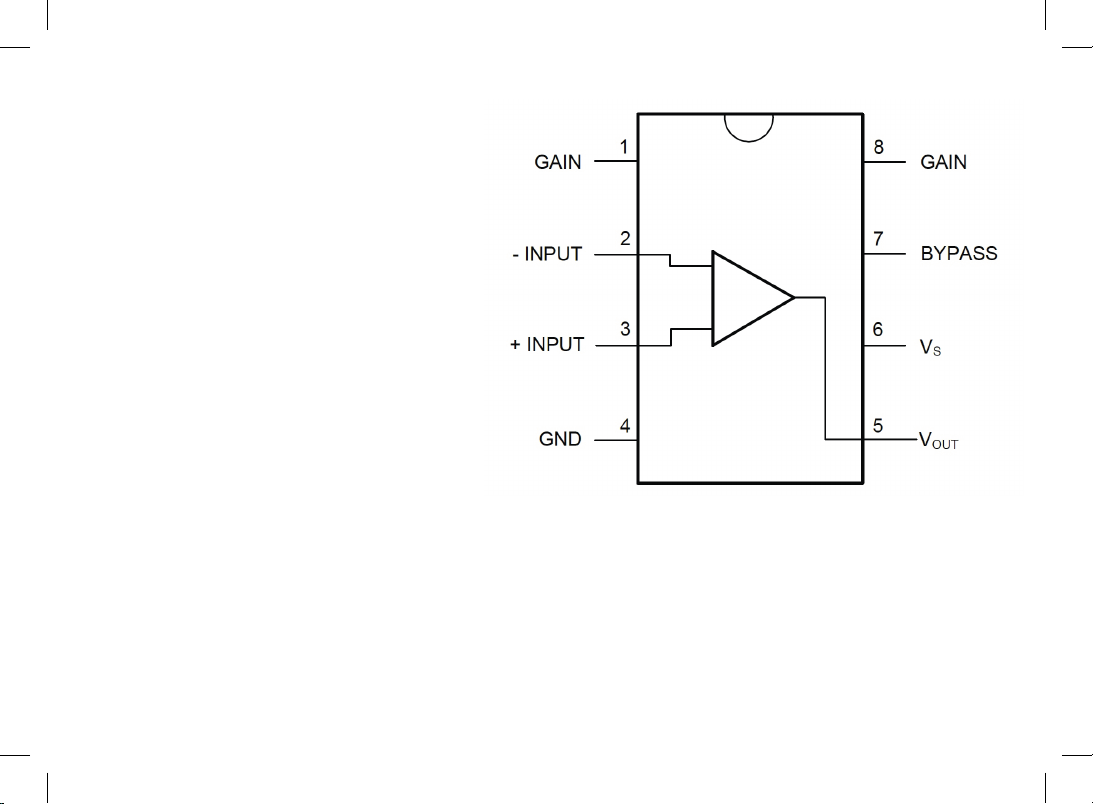
LoudspeakerLM386 amplier
The LM386 loudspeaker amplier is an integrated circuit (IC)
in a housing with eight pins, numbered from pin 1 at the bot-
tom le corner to pin 8 at the top le corner. Pin 4 (boom
right) is the negave terminal of the power supply. The ampli-
er operates at 9 V and provides 0.5 W to the loudspeaker.
The loudspeaker exhibits a resistance of 8 Ohm and can
tolerate up to 0.5 W. The volume depends mainly on how the
loudspeaker is mounted. A pleasant sound is only achieved by
installing the loudspeaker in the housing.
7

100 µF e-cap
100 nF disc capacitor
The loudspeaker must not be
connected directly to the am-
plier but requires a capacitor.
Any capacitor consists of two
metal sheets insulated against
each other. The electrolyc
capacitor (e-cap) used here
contains aluminium sheets in a
conducve uid (electrolyte).
You have to pay aenon to
the mounng direcon as
the e-cap will be destroyed
when the polarity is reversed.
The negave terminal is the
shorter leg; it is addionally marked by a
white bar. The kit contains two idencal
e-caps with a capacitance of 100 microfa-
rad (100 µF).
There is another capacitor with only a
1000th of the capacitance of the e-cap,
i.e. 100 nanofarad (100 nF). The im-
printed number 104 means 100,000 pF
(picofarad). This component is a ceramic
disc capacitor and can be mounted in
any direcon.
8

10 kΩ and 1 kΩ resistors Tuning potenometer
The resistors in the kit are of the carbon lm type and can
be mounted in any direcon. The smallest one has a resis-
tance of 100 ohm (100 Ω), the biggest one has 220 kiloohm
(220 kΩ). The resistance values are shown by three coloured
rings. The fourth, gold ring represents a tolerance of 5%. The
kit contains four resistors in total.
100 Ω: brown, black, brown
1 kΩ: brown, black, red
10 kΩ: brown, black, orange
220 kΩ: red, red, yellow
Basically, a potenometer is a resistor; however, it contains a
third contact, which is shied by turning the axis. The poten-
ometer will be mounted in the radio housing with a washer
and a nut, and a rotary knob will be screwed to the axis. This
three-pin potenometer is intended for tuning the radio.
9

The volume potenometer contains an addional switch and
thus has ve connecng wires. By turning the axis to the far
le, the radio is turned o. As a special feature of this poten-
ometer, the resistance curve is not linear but adapted to the
human sense of hearing. Hence, the middle seng provides
signicantly more than half the total resistance.
Volume potenometer
10

Loudspeaker
Baery with clip
Strain relief
100 µF e-cap
LM386 amplier
1 kΩ resistor (brown, black, red)
Step 1: Mounng the Amplier
Required components:
Breadboard, LM386 amplier IC,
100 µF e-capacitor, 1 kΩ resistor (brown,
black, red), hook-up wire
11
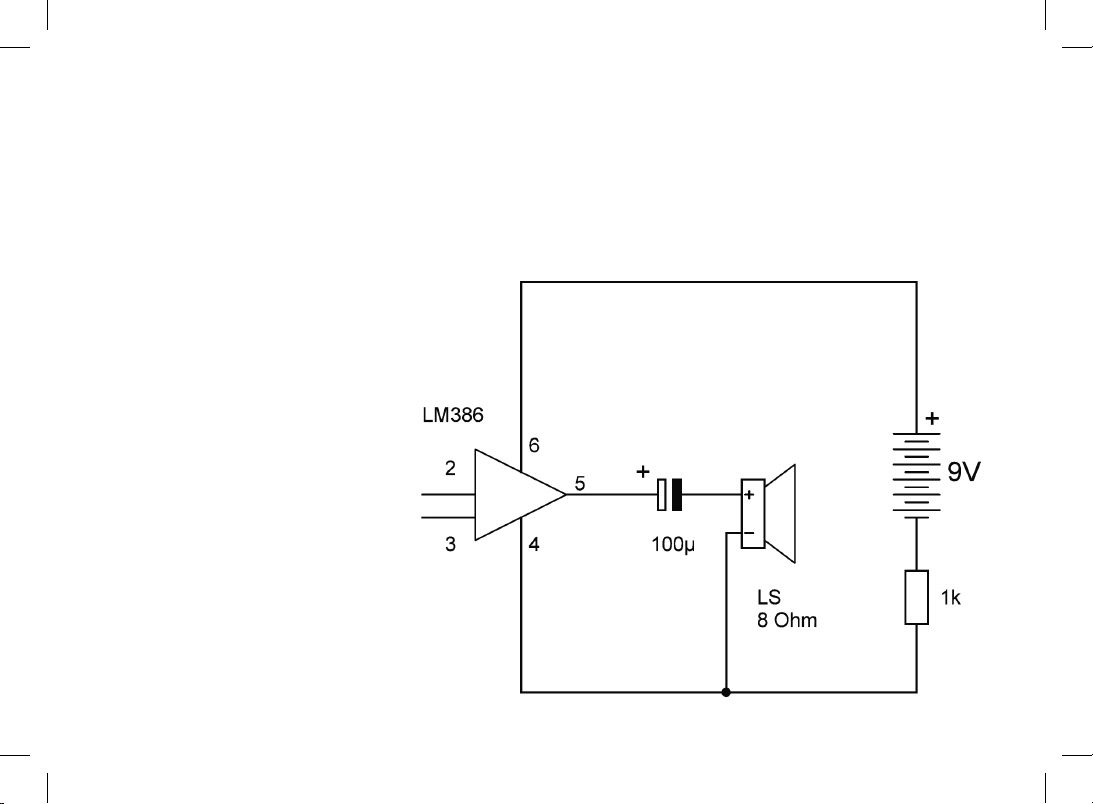
The eight-legged LM386 IC is a loudspeaker amplier
suited for baery operaon. Internally, it contains
many transistors and resistors.
Pin 4 of the IC (GND) connects to the negave termi-
nal of the baery via a 1 kΩ resistor (brown, black,
red) in order to limit the current in case of improper
assembly. The posive terminal is aached to pin 6
(Vs). Pin 5 is the output (Vout). Here, the loudspeak-
er is aached via a 100 µF e-cap. This pin supplies
an average output voltage of approx. 4.5 V. Thus, the
posive terminal of the e-cap has to point towards
the IC and the negave terminal (marked by a white
bar) to the loudspeaker. Pins 2 and 3 are the inputs
of the amplier and remain unaached for the me
being.
Let’s start with the rst step and insert the compo-
nents on the breadboard as shown in the illustraon.
Inserng components in the breadboard requires
some force. The connecon wires thus tend to bend.
It is important to insert the wires in a straight line
from above. Forceps or small pliers may come in
handy. Grip the wire a short distance above the breadboard und push it downwards. This way, you can even insert sensive
wires like the nned ps of the connecng wires of the baery clip or the loudspeaker without bending. If it is hard to insert
the wires, use a needle to widen the contacts on the breadboard a lile.
For the wire connecons, you need hook-up wire. Cut appropriate lengths of wire and remove 5 mm of the insulaon at the end.
You can strip o the insulaon with your ngernails or with pliers. Alternavely, you can remove it with the help of a sharp knife.
12
Inially, the eight legs of the IC have a slightly widened stance and must be aligned in parallel rows. This is best done with
pliers. Only now it is possible to insert the IC in the breadboard without eort. Be careful to mount the chip in the correct direc-
on. A notch at the le side marks pins 1 and 8.
The assembly drawings show exactly what contacts have to be used. Carefully observe all the drawings. When you adhere to
them, everything will work just ne!
As most of the components will remain in the same posion, it already makes sense to install a strain relief for the baery
wires at this stage to prevent the baery clip from damage. Remove the insulaon from the ends of a piece of wire of approx.
2 cm and insert it in the breadboard as shown. Cauon: Do not establish a conducve connecon with the strain relief!
When you turn on the baery, you will
hear a low clicking noise from the loud-
speaker. Touch pin 2 or 3 with a piece of
bare wire or another conducve object.
Now a clicking or humming noise can be
heard. By touching the pins, you apply a
small signal voltage to the input.
13

14

Step 2: Sound Generator
Required components:
10 kΩ resistor (brown, black, orange)
15

This circuit uses the 10 kΩ resistor (brown, black, orange) to turn the amplier into a sound generator. For natural oscillaons
to emerge, the non-inverng input at pin 3 of the LM386 has to be connected to the output via a resistor. This feedback gener-
ates oscillaons of the amplier, which become audible in the loudspeaker as humming or clicking.
Pin 2 of the LM386 is an inverng input. When the voltage at this input increases, the amplied voltage at the output decreas-
es. In contrast, pin 3 does not invert the signal: any input signal is amplied at the output but keeps its phase. By the feedback
on pin 3, oscillaons are generated.
This experiment proves that the
amplier is aached correctly and
works properly. The protecve 1 kΩ
resistor within the negave connec-
on is thus no longer needed. When
you bypass it with a piece of wire or
remove it for a test, the raling noise
becomes very loud.
16

17

Step 3: Improved Amplier
Required components:
100 nF disc capacitor,
100 µF e-capacitor,
hook-up wire
18

Capacitors are oen used to
transfer sound frequency signals.
Here, we use a ceramic 100 nF
disc capacitor (labelled 104). This
amounts to just a 1000th of the
capacitance of the 100 µF e-cap.
A 100 nF capacitor is ideally suit-
ed as a coupling capacitor at the
amplier input.
The 1 kΩ protecve resistor is re-
placed by a piece of wire because
aer the successful inial test,
there is no longer a risk of a faulty
circuit. Later, you will insert the
main switch of the radio in this
place.
Pin 3 of the amplier is now
addionally connected to GND.
This reduces distorons that
would otherwise occur by contact
resistances on the breadboard.
Pin 2 of the IC is the amplier input, which will later be con-
nected to the radio module via the capacitor. Touch the wire
of the capacitor. Again, you will hear low disturbing sounds
from the loudspeaker, e.g. a buzzing or humming. It originates
in the electrical wires and devices in the room, is received by
your body like an antenna and then amplied and made audi-
ble. This simple buzz test is helpful to test the amplier. It can
also be used to troubleshoot the completed radio later on.
19

20
Table of contents


