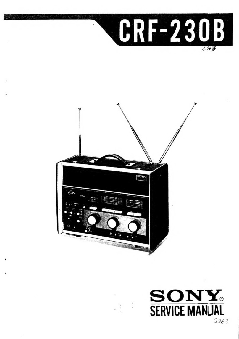
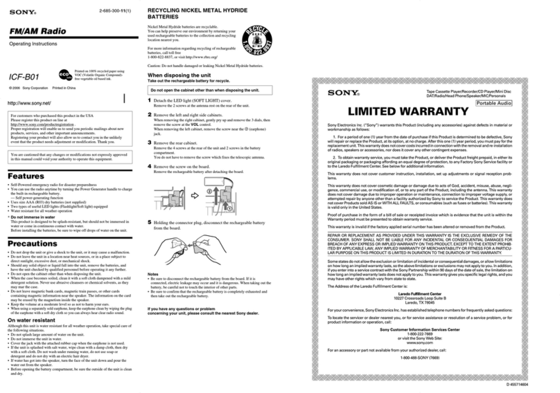
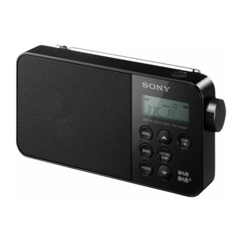
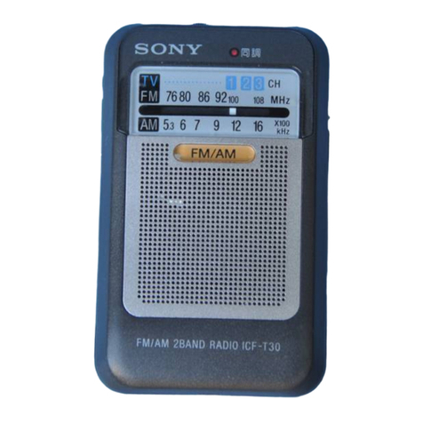
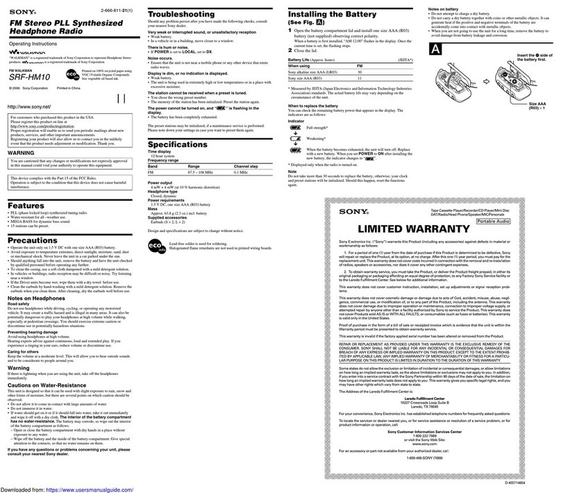
Sony CRF-230 User manual

-
v
v
SOhTY*
SERI,ICE MANUAL
,1
/

Section Title
ourLINE ........... 3
l-1. Specifications ....................................... 3
l-2. Block Diagram ....................................... 5
l-3. Technical Features................................. 6
l-4. Circuit Explanations.............................. 6
l-5. External View .......................................10
l-6. Internal View..........................................10
l-7. Chassis View ..........................................11
DTSASSEMBLY ......................12
2-1. Rear Cover Removal.................,............ I 2
2-2. Cabinet Removal ..........12
2-3. FrontPanel Removal ...........................13
2-4. Speaker Removal ..........13
2-5. Fm Front End Removal........................14
2-6. A-m I-f Circuit Board Removal .........14
2-7. Fm I-f Block Removal ........................15
2-8. Cp Circuit Board Removal .........'........16
2-g. Bfo Block Removal ..............................17
2-10. Sw Front End Removal ........................17
2-ll. Af. Circuit Board Removal ..................18
2-12. Regulator Circuit Board Removal .....18
2-13. Power Supply Circuit Board
Removal .......................19
2-14. DiaI Cord StringinC .................. ............20
CIRCUIT ADJUSTMENTS ................. ..........22
3-1. Preparation ...................22
3-2. A-m I-fAlignment ..............................22
3-3. Ssb Detector Adjustment ..............'.'.22
3-4. Fm I-f Alignment ..........23
3-5. Muting Level Setting ...........................24
3-6. FM l/FM2 Frequency Coverage
and Tracking Adjustment ..................24
3-7. LWMWSWI Frequency Coverage
and Tracking Adjustment ..................26
3-8. SW2-SWl9 lst I-f Alignment,
Frequency Coverage and
Tracking Adjustment ........................27
TABLE OF CONTENTS
Page Section Title Page
3-9. SW2-SWl9 Frequency Coverage
and Tracking Adjustment ..................28
3-10. Voltage and Current Adjustment ......32
MOI.]NTING AND SCHEMATIC
DTAGRAMS ............................33
4-1. Bfo Block (BFO-1A) ...........................33
4-2. Jack Panel ......................34
4-3. Antenna Terminal ..............................35
44. Fm Front End Block
(FMC-l 38A l ) ( r ) ............ ...............36
4-5. Fm Front End Block
(FMC- l 38A I ) (2) ............ ...............37
4-6. SW2-SWl9 Front End Block
(swc-o1 lDl) (l) ...........................38
4-7. SW2-SWI9 Front End Block
(swc-01 rDl) (2) ...........................40
4-8. FM I-f Block (IF-5A) .......................43
4-9. Am I-f Circuit Board ...........................45
4-10. Cp Circuit Board .................................47
4-l l. Regulator Circuit Board ......................49
4-12. Power Supply Circuit Board ............50
4-13. Af Circuit Board .................................51
4-14. Schematic Diagram .............................. 53
ELECTRJCAL PARTS LIST ............ ............ s 7
E)fLODED VIEW AND PACKING ,........66
6-1. Hardware Nomenclature .....................66
6-2. Exploded View (l) .......................... .. 6'
6-3. Exploded View (2) ..............................69
6-4. Exploded View (3) ........................... ..-l
6-5. Exploded View (4) ......................... --:
6-6. Exploded View (5) ....................... ... -i
6-7. ExplodedView(6) ............................. -t,
6-8. Exploded View (7)
6-9. Packing ........................... -9
v
2-
J

1-1. SPECtFtCAT|ONS
Circuit System:
Semiconductor:
Frequency Coverage:
Intermediate Frequency:
Antenna System:
Power Requirement:
Power Output:
at 1O% distortion
Current Drain:
at zero signal
Maximum Sensitivity:
at output 50 mW, S/N 6 dB
sEcTroN 1
OUTLINE
Superheterodyne (FM-1, FM-2, MW, LW, SW-l)
Double superheterodyne (SW-2 - SW-l9)
27 transistors, 3 FET for reception, I 8 transistors
for auxiliary functions, 34 diodes, I thermistor
FM-I
FM-2
MW
LW
sw-1
sw-2
sw-3
sw-4
sw-5
sw-6
sw-7
sw-8
sw-9
64 - 90 MHz
87 - 108 MHz
530 - 1,605 kHz (566 - 187 m)
150 - 400 kHz (2,000 - 750 m)
1.6-2.2 MHz (160 m)
2.0 - 2.6 MHz (l 20 m)
3.0 - 3.6 MHz (90 m)
3.5 - 4.1 MHz (75 - 8l m)
4.5 - 5.i MHz (60 m)
5.8 - 6.4 MHz (49 m)
7.O - 7.6 MHz (40 - 41 m)
9.5 - l0.l MHz (31 m)
I 1.5 - I 2.1 MHz (25 m)
14.0 - I 4.6 MHz (20 m)
15.0 - I 5.6.MHz (19 m)
17.5 - 18.1 MHz (16 m)
2l.O - 21.6 MHz (l 5 m)
21.4 - 22.0 MHz (13 m)
25.5 - 26.1 MHz (1 I m)
26.8-27.4 MHz (ll m)
28.0 - 28.6 MHz ( l0 m)
28.6 - 29.2 MHz ( l0 m)
29.2 - 29.8 MHz ( l0 m)
10.7 MHz
455 kHz
l st : 1.6 - 2.2 MHz
2nd: 455 kHz
telescopic antennas 1,000 mm 2 pcs
external antenna terminals
(300o, 75sl) are provided
built-in ferrite bar antenna, 100 x 180 mm
external antenna terminal is provided
-2 dB (0.8 pV)
28 dB/m (25 pY lm)
36 dB/m (63 s.V/m)
0 dB (l pV); average
SW-10;
SW-I I;
SW-l2;
SW-I3;
SW-I4;
SW-I5;
SW-I6;
SW-I7;
SW.I8;
SW.I9;
FM
MW, Lw'SW-l
sw-2 - sw-l9
FM
AC
DC
DC
SW.I, MW LW;
SW-2 - SW-19 ; telescopic antenna 1,470 mm
external antenna terminal is provided
100, ll7,220,240y, so/do Hz (c/s)
9V, battery size "D" 6 pcs
l2V, with SONY car battery cord DCC-2AW
3 W with AC power supply
1W with DC power supply
AC 250 mA
DC 140 mA
FM
MW
LW
SW
3-

Selectivity:
Muting kvel:
Signal-to-Noise Ratio :
Image Frequency Rejection: FM-l
FM-]
MW
LW
sw-l
sw-2
Frequency Response:
AUX Input Jack
input impedance:
maximum sensitivity:
MPX Output Jack
output impedance:
output level:
Recordirry Jact
output impedance:
output level:
Recording Connecta
output impedance:
output level:
Extengrl Speaker leck:
Headphor hck:
Earphore Ieck:
Other Contok:
fXrerbm:
ltefht:
Supplitd Acsuies:
LW, Utt; 30 dB at BROAD position
45 dB at SHARP position
SW : 50 dB at BROAD position
60 dB at SHARP position
l0 - 30 dB (adjustable)
FM, 63 dB at 54 dB input. 4OO Hz, 30% modulation
MW; 37 dB at 60 dB input. 4(n Hz, 30% modulation
LW; 30 dB at 60 dB input, {OO Hz, 30% modulatbn
SW ; 44 dB at 44 dB input- 4OO Hz, 30% modulatioa
U
77 dB
72 dB
60 dB
80 dB
70 dB
80 dB
30 dB
at 77 MHz
at 98 MHz
at 1,605 kHz
at 360 kHz
at 2MHz
at 2.5 MHz
at 29 MHz
SW-I9:
lm - 20,000 Hz t3 dB (flat rusponse)
5ko
-53 dB (1.7 mV) at 50 mS ofiFt
5ko
-14 dB (49 inv) at 5 kn lood inpcdance
2-2 ko
-5o dB (2.5 mV)
80 ko
-s0 dB (2.5 mV)
3 - 8o speakers can bc mr,stcd
8o headphone can be mctod
8!-l earphone can be comgad
Battery check switch
Calibrator reset knob
AGC/MGC knob
BFO control knob
Selectivity switch
Noise limiter switch
Muting switch
Sensitivity switch
17 t3/ro" (W) x l2rVt." (Hl r 7 Vz" @)
(452mmx325mmxlFru)
3l lb, 14 kg (witbd hrtF*)
AC power cord
polishing cloth o
-4

I
1.2. BLOCK DIAGRAM
L_
F
t
{
:t
U
-t
T---
q
ss
su
s$
s
{
s
\
:
q
EI
d1
i-l
ol
it
$r
t1
,l
Ysl
:t
EI
'l
s
{
i
c
J
t
t,
a
.
I
t
o
\
ts
a
{
ts
t
{F
:
{
s
s
t
s
{
c
s
o
a
r1"l
l"
lr*
lo
+e
F
I
{
t
{
5
Fig. t-l
L-
L-

1.3. TECHNICAL FEATURES
The SONY Model CRF-230 is a high-performance
radio receiver having many features found in commu-
nication receivers. Among them are the following:
o A total of 23 bands covering the broadcast fre-
quencies of any country in the world. Included are
2 fm bands, 19 sw bands, a mw band and a lw
band.
o FET (Field Effect Transistor) front ends in fm and
sw bands provide superior sensitivity, image rejec-
tion, and stability.
o Easy-to-tune sw bands due to a dual-conversion
system providing a uniform 600 kHz tuning range
on each band.
o Product detector for receiving ssb signals.
r An fm i-f circuit employing ceramic filters. An a-m
i-f circuit employing two ceramic filters with
four-step adjustable selectivity.
o Individual tuning knobs for sw bands, mw/lw
bands and fm bands. Preset-tuning of three sta-
tions is available.
The power supply will operate from household
current in any country of the world (via built-in
voltage selector), internal battery, or car battery.
Stable, noise-free fm tuning by means of AFC and
a muting system.
ANL (Automatic Noise Limiter) to minimize
noise.
Up to 3 watts of undistorted audio power output
with two built-in speakers or external speakers.
1-4. CIRCUIT EXPLANATIONS
AFC (Automatic Frequency Control)
Available for Both FM Bands:
In the Model CRF-230, the local oscillator fre-
quency is above the signal frequency for the FM-l
band, but below the signal frequency for the FM-2
band. Because of this, oscillator drift produces a
detector dc output-voltage change of difference polar-
ity on the FM-l band than occurs on the FM-2 band.
Therefore, dc control voltages taken directly from the
detector output can not be used to stabilize the fre-
quency of the local oscillator. To get around this
problem, a comparator circuit with selectable output
polarity is used (Fig. 1-2). The detector output is
divided by equal-value resistors R232 and R233 to
provide two voltages identical in magnitude but op-
posite in polarity. These voltages are compared against
a reference voltage of approximately 1.5 volts pro-
duced by the forward voltage drop across diodes
D2O4 and D205. The resultant voltages are applied to
the bases of transistors Q2l 2 and Q213. The FM
band selector switches automatically select the proper
collector voltage for the band in use and feed this
voltage through AFC switch S903 to variable-
capacitance diode Dl0l. This diode is voltage
sensitive, so its capacitance (and hence the oscillator
frequency) depends on the magnitude of the control
voltage. Load resistors R258, R259. R260 and R26l
of transistors Q2 12 and Q2 13 are connected in a
balanced-bridge circuit. The constant voltage at the
junction of R260 and R26l is used as a fixed bias
voltage for variable-capacitance diode Dl01 when
AFC switch 5903 is set to OFF.
lo AF Circuil
AFC SsoJ
Fig. l-2
a,
To AFC Circuil
6

tt Muting Circuit:
When the receiver is detuned from a signal, the
signal decreases. Since less i-f signal is then rectified
by diodes D2O7 and D208, the negative output voltage
of these rectifiers can no longer back the positive
voltage applied to the base of transistor Q207
through adjustable resistor R265 (FiC. l-3). This
allows Q207 to conduct lowering its collector voltage.
Since the collector of Q207 is connected to the base
of PNP transistor Q2 10, Q2 l0 conducts when its base
voltage decteases (with respect to ground), thereby
causing transistor Q209 to conduct. The collector
voltage of Q209 then drops to near ground potential.
The voltage at the collector of Q209 is fed to the base
of transistor Q405 through MUTING switch 5904.
Since this voltage is so low Q405 cannot conduct and
complete the emitter circuit of transistor Q404. This
prevents Q404 from amplifying the detector output.
When tuned to a signal, the opposite actions
occur. I-f signal through capacitor C228 is rectified
into negative d-c voltage by diodes D207 and D208.
This voltage cuts off transistor Q207 and eventually
turns on transistor Q405, thereby enabling transistor
Q404 to amplify the detector output. The muting
level can be adjusted by potentiometer R265. The
muting level is usually set approximately 20 dB lower
than the signal level. If the receiver tuning is shifted
within range B of Fig. 1-4, the difference between the
collector voltages of transistors Q212 and Q2l3
becomes large enough drops across resistors R254 and
R255, thus lowering the base voltage of PNP tran-
sistor Q2 l0 and results in its conduction. As before,
the conduction of Q2 l0 begins a chain of events
which prevents Q404 from amplifying. If the tuning
is shifted within range C of Fig. l-4, the difference
between the collector voltages of transistors Q2 l2
and Q2 13 is so small that transistor Q2 l1 is turned
off within this range as well as in range A. Noise
components caused by detuning, however, are
coupled to transistor Q208 through capacitor C234
and resistor R249 from the detector output.
C-f-a-f-- A-_-+-B-)--c
Fig. l-4 Discriminatorcharacteristic
!
v
trom
d r sc.rmr notor
O2lA .27a
_ wlt--"
a209 R252 R249
9
7
Fig. l-3

The noise is amplified, rectified into negative d-c
voltage by diodes D2l0 and D2 I l, and applied to the
base of transistor Q2 l0 to turn it on. Since the base
voltage of Q208 is controlled by the collector voltage
of Q210, the amplification of transistor e208 in-
creases due to increased base bias, and transistor
Q210 is held conducting quite reliably. As before,
transistor Q404 cuts off the detector output.
Positive feedback through resistor R252 and
capacitor C235 from transistor e2 l0 aids in turning
off Q209.
Adjustable Selectivity E mploying Ceram ic Filters:
The bandwidth in a-m reception can be altered
by changing the coupling between the sections of
ceramic filters in the a-m i-f circuit. When bands SW2
through SWl9 are selected, ceramic filter CF50l is
automatically set to narrow bandwidth by switch
5501. Similarly, when bands LW, MW or SWI are
selected, a wide bandwidth is automatically selected.
Ceramic filter CF502 can be manually set to
narrow or wide bandwidth by switch 5502. When set
to SHARP, switch 5502 also connects in the high+ut
filter consisting of coil L507 and capacitors C537,
C538 and C541.
The net result of the switch manipulations on the
ceramic filter circuits are summarized in Table. The
overall selectivity curves of the a-m i.f strip at each of
the four possible switch combinations are shown in
Fig. l-5.
Band
setting cF501 (3501-1-4) cF502 (5502-1-41 High-cut
filter
(s502-5, 6)
Overall
response
(Fie. l-5)
Band
width C.oupling Band
width Coupling
sw2
through
swl9 Sharp
c523 R528 Sharp f* ON A
Broard OFF
LW
MW
swl Broard
c522 R527
r
f-] our
Sharp ON C
Broard OFF D
8-

U
Fis. 1-5
-5 0 +5 +D +15
Fr€quency (KHz)
Overall i-f rcsponv curue
ANL (Automatic Noise Limiter):
This limiter in the a-m section clips any noise
pulses accompanying the signal to a level no longer
than the signal amplitude. The clipping level is auto-
matically adjusted to match the variations in signal
level. The collector voltage of i-f amplifier Q502 for-
ward biases diodes D506 and D507 through resistors
R509 and R521, while the output voltage of detector
D50l provides a reverse-bias voltage (Fig. l-6). These
two bias voltages adjust the clipping level of diodes
D506 and D507 to match the average signal level.
Product Detector for Single-Sideband Reception:
A product detector is a type of heterodyne
detector. Single-sideband signals can be recovered by
passing them through nonlinear device after being
mixed with a carrier identical in frequency to that
used during modulation at the transmitter. That is,
these two signals, sideband and carrier, are converted
into two beat signals, upper and lower, against the
carrier frequency by heterodyne action. The upper
beat signal is eliminated by passing through the filter
circuit and the lower beat signal is fed to the next
stage as audio signals.
In the model CRF-230, the detector utilizes the
square-low characteristic (output current propor-
tional to the square of the effective value of the input
voltage) of a diode for the nonlinear device.
To minimize distortion, two diodes D5O2, and
D503 are connected in reverse each other and applied
the signals respectively positive in phase. That is
because the range of square-law curve of one diode is
narrow causing distorted detection for strong input
signal.
The BFO injection voltage used for carrier re-
insertion is comparatively high (about 0.8 volt is
optimum) to set the operating point of the detector
within a linear portion of the diodes' characteristic.
This results to minimize distortion of the recovered
audio signal.
filler
-to
U
ssB
i-f signal
Automatic noise limiter circuit
Rsre l--------l
rernsert corrier
frohBFO
Fig. I -7 Product detector
Rd7 il dt
I Ttr" cri
I L_______t_
tL
delecled
signql
F
I
Fig. l-6
9-

1-5. EXTERNAL VIEW
x-38276-86
knob ass'y,
calibrator
x-38276-85
knob ass'y, control
(TONE. VOLUME)
x-38276-84
knob ass'v, control
IMGC. BFO)
1.6. INTERNAL VIEW
1-401-347
antcoil, SWI
bar antenna
Fis. 1-8
1-502-21 0
speaker
3-828-422
button, push switch
x-38276-83
knob ass'y, tuning
x-38276-87
lever as'y, BFO
Y-38521-01-l
front end biock. SW
(swc-]t t D1 )
1-501-1 01-1 E
telescopic antenna, SW
1-526-16U11
voltage selrctor
1-533-U8
fuse holder
t-56-078
socket, a plug
7-50902901
conn*tor, TAPE
t-507-16913
jek, AUX tN/REC OUT/
MPX OUT/EXTSP
circuit board, cp
,-501-103-12
telesopic antenna, fm
1-401-34tj
ant coil, MW/LW bar antenna
3-828-470
panel, antenna
1-514-304
slide switch,
ROD/EXT an
t-222-149-t I
potentiometer, muti ng level
- 10 -
Fis. l-9

tt 7-7. CHASSTS VIEW
- Front -
x-38276-95
bnd indicator xs'y, SW
x-38276-93
svvitch "8" ass'y, battery
check and light batterv
check and light
,-222-r95
tone control
,-514-W3-rt
lever seesaw switch,
pouer on
1-507-r9Gt2
jxk, headphone
1-507-r69-r3
jxk, earphone
t-222-t94-12
volume control,
MGC
- Bottom -
Y-3869001-l
BFO block IBFO-1A)
mounted circuit board.
pounr supply
Y-38553-Or-1
mounted circuit board,
af
U
Fis. 1-lO
Fig. l-11
x-38276-94.
mounted circuit board,
a-m i-f
Y-38522-01-l
front end block, fm
(FMC-l38A1)
mounted circuit board,
regulator
x-38276-90
dial indicator ass'y,
sw?t9
x-38276-92
dial indicator as'v.
LMMWEWI
x-38276-9'
dial indicator ass'v. FM
r,
- 1l -
Table of contents
Other Sony Radio manuals

Sony
Sony Walkman ICF-S10MK2 User manual

Sony
Sony Walkman SRF-HM55 User manual

Sony
Sony Walkman SRFM-85V User manual

Sony
Sony SRF-PSY04 User manual

Sony
Sony SRF-46 User manual

Sony
Sony XDR-S50 User manual

Sony
Sony CFS-715S User manual

Sony
Sony XDR-S10HDIP User manual

Sony
Sony ICF-M88B User manual

Sony
Sony ICF-SW1 User manual

Sony
Sony TFM-8100W User manual

Sony
Sony XDR-S1 User manual

Sony
Sony Walkman WM-GX670 User manual

Sony
Sony ICF-M33RDS User manual

Sony
Sony ICF-SW12 User manual

Sony
Sony WALKMAN SRF-M80V User manual

Sony
Sony SRF-M90 User manual

Sony
Sony ICF-S22 User manual

Sony
Sony ICF-SW12 User manual

Sony
Sony XDR-P1DBP User manual