EINHELL SO 6-M User manual

®
Art.-Nr.: 41.906.00
Bedienungsanleitung
Solar Modul
Operating Instructions
Solar Module
Mode d’emploi
Module solaire
Gebruiksaanwijzing
Zonmodule
Manual de instrucciones
Módulo solar
Istruzioni per l’uso del
Modulo solare
SO 6-M
Anleitung SO 6-M 07.11.2001 15:23 Uhr Seite 1

2
Herzlichen Glückwunsch Sie haben ein hochwertiges
Solarmodul erworben. Bitte lesen Sie die
Bedienungsanleitung vor der Montage und
Inbetriebnahme des Moduls vollständig durch und
achten Sie auf die Hinweise. Für Schäden, die durch
Nichtbeachtung der Bedienungsanleitung verursacht
werden übernehmen wir keine Haftung. Das
Solarmodul ist für den Einsatz im privaten Bereich
zum Laden von Akkus oder Direktantrieb (z.B.
Pumpen) konstruiert worden.
1. Lieferumfang:
1 St. Solarmodul 12V / 6W
1 St. 10m Verbindungsleitung mit Überladeschutz
2. Technische Daten:
Leistung des Solarmoduls: 6W
Nennspannung des Solarmoduls: 14,5V
Leerlaufspannung des Solarmoduls: 22,5V
Nennstrom des Solarmoduls: 390mA
Abmessung des Solarmoduls: 45 x 31cm
3. Funktionsweise und Montage des
Solarmoduls
Ein Solarmodul wandelt auftreffendes Sonnenlicht in
elektrische Energie um. Mit dieser Energie können
z.B. Akkus geladen oder Geräte wie z.B. Gleich-
strompumpen betrieben werden. Die abgegebene
Leistung des Moduls ist abhängig von der Sonnen-
einstrahlung. Bei wolkenlosen Himmel und direkt
auftreffenden Sonnenstrahlen erreichen Sie die max.
Modulleistung. Stellen Sie deshalb das Modul mit der
Vorderseite (rot / braune Seite) in 45° Neigung
Richtung Süden. Das Modul kann durch eigene
Haltekonzepte montiert werden. Achten Sie dabei
daß die Sonneneinstrahlung während des Tages
nicht durch Büsche oder Bäume verhindert wird. Die
Sonne muß vollständig auf das Modul auftreffen bei
Teilabschaltung erhält man nur geringe
Modulleistungen. Bitte beachten Sie bei der
Aufstellung, daß das Solarmodul bruchempfindlich ist
und keiner mechanischen Belastung ausgestzt
werden darf. Ein beschädigtes Modul kann nicht
repariert werden, es muß umweltgerecht entsorgt
werden.
4. Elektrischer Anschluß
An der Rückseite des Moduls wird das beiliegende
Kabel angeschlossen. Der Stecker des
Anschlußkabels ist verpolungsgeschützt. Es darf bei
Einstecken keine Gewalt angewandt werden.
5. Anschluß von Verbrauchern
Achten Sie bei der Auswahl Ihrer Geräte darauf, daß
diese für den direkten Anschluß an ein Solarmodul
geeignet sind. Hier ist besonders zu beachten, daß
das Solarmodul je nach Sonneneinstrahlung eine
Leerlaufspannung bis zu 22,5V und 14,5V bei einem
Gleichstrom bis 390mA abgeben kann. Es eignen
sich also nur Geräte, die bereits bei niedrigem Strom
anlaufen und einen entsprechenden
Betriebsspannugsbereich besitzen.
6. Laden von 12V Akkus
Das Anschlußkabel des Solarmoduls besitzt am
Ende einen Zigarettenanzünderstecker.
Das Solarmodul ist in der Lage Akkus über einen
entsprechenden Adapter (12 V
Zigarattenanzünderbuchse) mit einer Nennspannung
von 12V zu laden. Je nach Akkukapazität und
Entladetiefe richtet sich die Zeit für die Volladung des
Akkus. Das Modul kann effektiv bis zur Ladung eines
12V / 30 Ah Akkus eingesetzt werden.
Faustformel zur Berechnung der Ladezeit bei einem
25Ah Akkus:
1,1 = fester Ladefaktor
Zeit = 1,1 x (Ah des Akkus / Strom des Moduls)
Zeit = 1,1 x (25 Ah / 0,39 A)
Zeit = 70,5 Stunden
1
D
Anleitung SO 6-M 07.11.2001 15:23 Uhr Seite 2

7. Laden der Einhell Engergiestationen
Beim Laden der Einhell Engergiestationen gehen Sie
wie folgt vor:
Anschluß des Verbindungskabels wie oben
beschrieben.
Stellen Sie den Ein/Aus/Cha - Schalter der
Engergiestation in Stellung “Ein”
Schließen Sie den Zigarattenanzünderstecker in
die 12V Buchse der Engeriestation.
Die Ladezeit richtet sich wie oben beschrieben
nach dem jeweiligen Batteriezustand.
8. Hinweise
Die eingebauten Schutzdioden in der Anschluß-
leitung verhindert einen Rückstrom in das Modul.
Dieser Rückstrom würde bei Nacht oder unge-
nügender Sonneneinstrahlung entstehen. Hinweis!
Beim Anschneiden des Kabels ist der Schutz nicht
mehr gegeben.
Der eingebaute Überladeschutz verhindert ein
Überladen der Akkus, das heißt Sie brauchen das
Solarmodul nicht vom Akku trennen falls Sie die
entsprechende Ladezeit überschritten haben. Bei
14,1 Volt des Akkus unterbricht der Überladeschutz
die Ladung solange bis die Spannung wieder unter
die 14,1 Volt Grenze fällt.
9.Ersatzteilbestellung
Bei eventuellen Ersatzteilbedarf sollten folgende
Angaben gemacht werden:
Typ des Gerätes
Artikelnummer des Gerätes
Identnummer des Gerätes
Ersatzteilnummer des erforderlichen Ersatzteils
3
Ersatzteilliste SO 6 M Art.-Nr.: 41.906.00 I.-Nr.: 91017
Pos. Bezeichnung Ersatzteil-Nr.
01 Solarmodul 6W 41.906.00.01
02 Modulleitung komplett 41.906.00.02
D
Anleitung SO 6-M 07.11.2001 15:23 Uhr Seite 3

Congratulations! You have purchased a high-quality
solar module. Before installing and using the module
for the first time, please read and note all the
instructions. We can accept no liability for any
damage caused by failure to observe the operating
instructions. The solar module is designed for use in
the private sector to charge storage batteries or to
provide electrical equipment (e.g. pumps) with a
direct power source.
1. Items supplied
1 solar module 12V / 6W
1 connecting cable, 10 m, with overcharge
protection
2. Technical data
Solar module output: 6W
Solar module rated voltage: 14.5V
Solar module no-load voltage: 22.5V
Solar module rated current: 390mA
Solar module dimensions: 45 x 31 cm
3. Installing the solar module and its
mode of operation
A solar module transforms incidental sunlight into
electric energy. This energy can be used e.g. to
charge storage batteries or to power electric
equipment such as d.c. pumps. The module’s output
depends on the amount of sunlight it receives.
Maximum output is achieved under cloudless skies
and in direct sunshine. It is best, therefore, to align
the module facing south with its front (red/brown)
tilted 45°. The module can be fitted in position with
its own bracket arrangements. Make sure that the
sunlight is not obstructed in the course of the day by
bushes or trees. It is important for the complete
module to be exposed to the sunshine. Partial
deactivation will result in only a low output. The solar
module is a fragile component - install it with care
and protect it from mechanical loads! A damaged
solar module cannot be repaired but has to be
disposed of in an environmentally responsible
manner.
4. Fitting the connecting cable
Fit the supplied connecting cable to the back of the
module. The cable comes with a non-reversible plug.
Use no force to insert it.
5. Connecting up electric equipment
Be sure to choose only equipment that is suitable for
connecting directly to a solar module. Remember in
particular that, depending on the amount of incidental
sunlight, the solar module is able to produce a no-
load voltage of up to 22.5V and a rated voltage of
14.5V with a direct current of up to 390mA. Only
those items of equipment are suitable, therefore, that
require a low current to start up and which have a
matching range of operating voltage.
6. How to charge 12V storage batteries
The solar module connecting cable is fitted at the
one end with a cigarette lighter plug. With the right
adapter (12V cigarette lighter socket) the solar
module can thus be used to charge batteries with a
rated voltage of 12V. The time needed for a full
charge depends on the battery’s Ah capacity and the
level of its residual charge. Batteries of up to 12V /
30 Ah can be charged effectively by the module.
To calculate the charging time for a 25Ah battery,
use the following rule of thumb:
1.1 = fixed charging factor
Time = 1.1 x (battery Ah / module current)
Time = 1.1 x (25Ah / 0.39A)
Time = 70.5 hours
4
GB
1
Anleitung SO 6-M 07.11.2001 15:23 Uhr Seite 4

7. How to charge Einhell power
stations
Proceed as follows to charge Einhell power stations:
Fit the connecting cable as described above.
Set the On/Off/Cha switch of the power station to
„On“.
Insert the cigarette lighter plug in the 12V socket
of the power station.
Charging time depends on the actual state of the
battery as explained above.
8. Further notes
The protective diodes integrated in the connecting
cable prevent a reversal of current back into the
module. Without these diodes current reversal would
occur at night and in periods of poor sunlight.
Caution! Cutting the cable destroys this protective
function. The built-in overcharge cut-out prevents
overloading of the battery, i.e. there is no need to
disconnect the solar module from the battery even
when the necessary charging time is exceeded.
When the battery voltage reaches 14.1V, the
overcharge cut-out will interrupt the charge until the
voltage drops again below 14.1V.
9. Ordering replacement parts
If you ever need a replacement part, please quote
the following details:
Type of unit
Article number of the unit
ID number of the unit
Replacement part number of the item required
5
GB
Anleitung SO 6-M 07.11.2001 15:23 Uhr Seite 5

Félicitations! Vous avez fait l’acquisition d’un module
solaire de haute qualité. Veuillez lire complètement
le mode d’emploi avant le montage et la mise en
service du module et suivre les instructions. Nous
déclinons toute responsabilité concernant les dégâts
dus au non-respect de ce mode d’emploi. Le module
solaire a été conçu pour la charge d’accumulateurs
ou pour l’entraînement direct (p.ex. pompes) dans le
domaine privé.
1. Etendue des fournitures
1 Module solaire de 12 V /6 W
1 Câble de raccordement de 10 m avec dispositif
de protection contre les surcharges
2. Caractéristiques techniques:
Puissance du module solaire: 6 W
Tension nominale du module solaire: 14,5 V
Tension à vide du module solaire: 22,5 V
Courant nominal du module solaire: 390 mA
Dimensions du module solaire: 45 x 31 cm
3. Fonctionnement et montage du
module solaire
Un module solaire transforme la lumière solaire
reçue en énergie électrique. Avec cette énergie, on
peut par exemple charger des accumulateurs, ou
faire fonctionner des appareils comme par exemple
des pompes à courant continu. La puissance
débitée du module dépend de l’ensoleillement. Par
ciel clair et rayonnement direct, la puissance du
module atteint son maximum. Vous disposerez donc
le module de façon que sa face (rouge/brun) ait une
inclinaison de 45° vers le sud. Le module peut être
monté sur un support de conception personnelle.
Veillez cependant à ce que l’ensoleillement ne soit
pas empêché par des buissons ou des arbres. Le
soleil doit rayonner directement sur le module, sinon,
sa performance serait minimale. Au cours du
montage, considérez que le module est fragile et
qu’il ne doit être soumis à aucun effort mécanique.
Un module endommagé ne peut pas être réparé. Il
doit être éliminé de manière non polluante.
4. Raccordement électrique
Le câble électrique fourni sera raccordé au dos du
module. La fiche du câble de raccordement est
protégée contre la réversibilité des pôles.
N’employez pas trop de force pour mettre la fiche
dans la prise.
5. Branchement des consommateurs
Quand vous choisirez vos appareils, assurez-vous
qu’ils soient aptes à être directement raccordés à un
module solaire. Il faut particulièrement considérer
que, selon l’intensité de l’ensoleillement, le module
solaire peut fournir une tension à vide jusqu’à 22,5 V
et fournit 14,5 V avec un courant continu jusqu’à
390mA. Par conséquent, seuls les appareils qui
démarrent déjà avec une basse intensité de courant
et qui ont une marge de tension de fonctionnement
correspondante sont appropriés.
6. Charge d’accumulateurs de 12 V
Le câble de raccordement du module solaire est
muni d’une fiche allume-cigarettes à son bout. Le
module solaire est capable de charger des
accumulateurs avec une tension nominale de 12V
par l’intermédiaire d’un adaptateur correspondant
(prise allume-cigarettes de 12V). Le temps de
charge des accumulateurs dépend de leur capacité
et de l’état de charge. Le module peut être utilisé
effectivement pour la charge d’accumulateurs de
12V/30Ah au maximum. Règle générale pour
l’évaluation du temps de charge d’accumulateurs de
25 Ah:
1,1 = facteur fixe de charge
Temps = 1,1 x (Ah de l’accumulateur/ courant du
module)
Temps = 1,1 x (25 Ah/0,39A)
6
F
1
Anleitung SO 6-M 07.11.2001 15:23 Uhr Seite 6

Temps = 70,5 heures
7. Charge de la station d’énergie
Einhell
Pour charger la station d’énergie Einhell, procédez
comme suit:
Raccordement du câble de raccordement , voir
ci-dessus
Mettez l’interrupteur Ein/Aus
(MARCHE/ARRET) de la station d’énergie sur la
position “Ein” (MARCHE)
Branchez la fiche allume-cigarettes dans la prise
de 12V de la station d’énergie
Le temps de charge ( mentionné ci-dessus) varie
selon l’état de la batterie.
8. Remarques
Les diodes de protection intégrées dans le câble de
raccordement empêchent un courant de retour dans
le module. Un tel courant de retour pourrait se
produire dans la nuit ou sous un ensoleillement
insuffisant. Remarque! Une fois le câble sectionné,
cette protection n’est plus assurée.
La protection contre les surcharges intégrée
empêche une surcharge des accumulateurs, c’est-à-
dire que vous n’avez pas besoin de séparer le
module de l’accumulateur au cas où le temps de
charge aurait été dépassé. A la marque 14,1V des
accumulateurs, le dispositif anti-surcharge interrompt
la charge jusqu’à ce que la tension retombe au-
dessous de 14,1V.
9. Commande de pièces de rechange
Pour les commandes éventuelles de pièces de
rechange, vous devriez indiquer les références
suivantes:
Type de l’appareil
Numero d’ article
Numéro d’identification de l’appareil
Numéro de pièce de rechange de la pièce
demandée
7
F
Anleitung SO 6-M 07.11.2001 15:23 Uhr Seite 7

Proficiat met Uw aankoop van een zonmodule van
uitstekende kwaliteit. Gelieve vóór de montage en
inwerkingstelling de gebruiksaanwijzing volledig te
lezen en de aanwijzingen in acht te nemen. Wij zijn
niet aansprakelijk voor schade veroorzaakt door niet-
naleving van de gebruiksaanwijzing. De zonmodule
is bedoeld voor gebruik in de particuliere sector voor
het laden van accus of rechtstreekse aandrijving (bv.
pompen).
1. Levering
1 st. zonmodule 12 V / 6 W
1 st. 10 m verbindingskabel met beveiliging
tegen overladen
2. Technische gegevens
Vermogen van de zonmodule: 6 W
Nominale spanning van de zonmodule: 14,5 V
Nullastspanning van de zonmodule: 22,5 V
Nominale stroom van de zonmodule: 390 mA
Afmetingen van de zonmodule: 45 x 31 cm
3. Werkwijze en montage van de
zonmodule
Een zonmodule zet opvallend zonlicht om in
elektrische energie. Met deze energie kunnen bv.
accu’s geladen of toestellen zoals
gelijkstroompompen worden aangedreven. Het
afgegeven vermogen van de module is afhankelijk
van de zoninstraling. Bij wolkeloze hemel en
rechtstreeks opvallende zonstralen bereikt U het
maximumvermogen van de module. Plaats daarom
de module met de voorkant (rode/bruine kant) met
een helling van 45° richting zuiden. De module kan
door een eigen bevestiging worden aangebracht. Let
erop dat de zoninstraling overdag niet door struiken
of bomen wordt verhinderd. Het zonlicht moet
volledig op de module vallen; als de module
gedeeltelijk door schaduw wordt afgedekt krijgt men
slechts een verminderd modulevermogen. Gelieve er
bij het aanbrengen op te letten dat de zonmodule
breekbaar is en niet aan een mechanische belasting
mag worden blootgesteld. Een beschadigde
zonmodule kan niet meer hersteld worden en dient
onschadelijk voor het milieu te worden verwijderd.
4. Elektrische aansluiting
De bijgaande kabel wordt aangesloten aan de
achterkant van de module. De stekker van de
aansluitkabel is beschermd tegen een verwisselen
van polen - bij het insteken mag U dus niet forceren.
5. Aansluiten van verbruikers
Let er bij het kiezen van Uw toestellen op dat deze
geschikt zijn voor een directe aansluiting aan een
zonmodule. Gelieve er bijzonder rekening mee te
houden dat de zonmodule naargelang van de
zoninstraling een nullastspanning van maximaal 22,5
V en een nominale spanning van 14,5 V bij een
gelijkstroom tot 390 mA kan afgeven. Enkel deze
toestellen zijn geschikt die reeds bij lage stroom
aanslaan en een overeenkomstig
werkspanningsbereik hebben.
6. Laden van 12 V accu’s
De aansluitkabel van de zonmodule is aan het
uiteinde voorzien van een sigarenaanstekerstekker.
De zonmodule is in staat accu’s met een nominale
spanning van 12 V te laden via een gepaste adapter
(12 V sigarenaansteker-stopcontact). De tijd voor het
volledig opladen van de accu is afhankelijk van de
accucapaciteit en de ontlaaddiepte. De module kan
effectief worden gebruikt voor het laden van accu’s
tot 12 V / 30 Ah. Vuistformule voor het berekenen
van de laadtijd bij een 25 Ah accu:
1,1 = constante laadfactor
Tijd = 1,1 x (Ah van de accu / stroom van de module)
Tijd = 1,1 x (25 Ah / 0,39 A)
Tijd = 70,5 uur
8
NL
1
Anleitung SO 6-M 07.11.2001 15:23 Uhr Seite 8

7. Laden van Einhell energiestations
Bij het laden van Einhell energiestations gaat U als
volgt te werk:
U sluit de verbindingskabel aan zoals hier boven
beschreven.
Breng de IN/UIT/CHAR-schakelaar van het
energiestation naar stand ”EIN” (IN).
Sluit de sigarenaanstekerstekker aan aan het
12 V stopcontact van het energiestation.
De laadtijd is afhankelijk van de respectievelijke
toestand van de batterij zoals hier boven
beschreven.
8. Aanwijzingen
De ingebouwde beschermdioden in de aansluitkabel
voorkomen een keerstroom naar de module. Deze
keerstroom zou ‘s nachts of bij onvoldoende
zoninstraling kunnen ontstaan. Aanwijzing! Bij het
aansnijden van de kabel is de bescherming niet
meer gegeven. De ingebouwde beveiliging tegen
overladen voorkomt een overladen van de accu.
D.w.z. U hoeft de zonmodule niet te scheiden van de
accu indien de betreffende laadtijd is overschreden.
Bij 14,1 V van de accu onderbreekt de beveiliging
tegen overladen de laadbeurt totdat de spanning
opnieuw onder de 14,1 V drempel daalt.
9. Bestellen van wisselstukken
Indien U wisselstukken nodig hebt, gelieve dan bij
Uw bestelling volgende gegevens te vermelden:
Type van het toestel
Artikelnummer van het toestel
Ident-nummer van het toestel
Wisselstuknummer van het benodigd stuk
9
NL
Anleitung SO 6-M 07.11.2001 15:23 Uhr Seite 9

Le felicitamos, acaba de adquirir un módulo solar de
alta calidad. Antes del montaje y la puesta en
servicio del módulo rogamos se sirva a leer
atentamente todo el manual de instrucciones y
observe sus advertencias. No nos hacemos
responsables de los daños que puedan ocasionarse
por no haber seguido estas instrucciones. El módulo
solar ha sido diseñado para ser usado en el ámbito
doméstico, para cargar acumuladores o servir de
accionamiento directo (por ej. para bombas).
1. Alcance del suministro
1 Módulo solar 12 V / 6 W
1 Cable de conexión de 10 m con protección de
sobrecarga
2. Características técnicas
Rendimiento del módulo solar: 6 W
Tensión nominal del módulo solar 14,5 V
Tensión en vacio del módulo solar 22,5 V
Corriente nominal del módulo solar: 390 mA
Dimensiones del módulo: 45 x 31 cm
3. Funcionamiento y montaje del
módulo solar
El módulo solar transforma la energía de los rayos
solares en electricidad. Con esta energía se pueden
cargar acumuladores o hacer funcionar aparatos
eléctricos, como por ej. bombas de c.c. El
rendimiento del módulo depende grandemente de la
radiación solar. El rendimiento máximo se alcanza
en un día claro, sin nubes, cuando los rayos del sol
toquen directamente el módulo. Deberá pues colocar
el módulo con la parte delantera (lado rojo/marrón)
orientada hacia el sur, con una inclinación de 45º. El
módulo está dotado de un sistema de montaje
propio. Preste atención a que el módulo esté
expuesto al sol todo el día y no caigan sombras de
árboles o arbustos sobre él. El sol deberá tocar de
lleno, de lo contrario el rendimiento del módulo
disminuye considerablemente. El módulo solar es
frágil y no debe exponerse a cargas mecánicas. Un
módulo dañado no puede repararse y deberá ser
eliminado correctamente, sin perjuicio para el
medioambiente.
4. Conexión eléctrica
El cable suministrado se conecta en la parte
posterior del módulo. El enchufe del cable está
protegido contra una polarización inversa. No haga
fuerza para enchufar el cable.
5. Conexión de consumidores
Cuando elija los aparatos que deben ir conectados al
módulo, compruebe que éstos sean adecuados para
ir conectados directamente al módulo. En este caso
téngase en cuenta que el módulo solar puede
suministrar, según la radiación solar, una tensión en
vacio de hasta 22,5 V y 14,5 V con una corriente
continua de máximo 390 mA. Es decir, sólo se
podrán conectar aparatos que se pongan en marcha
con una corriente baja y que posean un campo de
tensión de servicio correspondiente.
6. Recargar acumuladores de 12 V
El cable de conexión del módulo solar está dotado
de un enchufe tipo encendedor de cigarrillos. Con el
módulo solar y un adaptador (12 V, hembrilla para
encendedor) se pueden recargar acumuladores a
una tensión nominal de 12 V. El tiempo requerido
para una carga completa del acumulador depende
de su capacidad y del nivel de descarga alcanzado.
El módulo puede utilizarse de forma efectiva para
recargar un acumulador de hasta 12V / 30 Ah. A
continuación se indica la regla empírica para el
cálculo de un período de recarga de un acumulador
de 25 Ah:
10
E
1
Anleitung SO 6-M 07.11.2001 15:23 Uhr Seite 10

1,1 = factor de carga fijo
Tiempo = 1,1 x (Ah del acumulador / Corriente del
módulo)
Tiempo 1,1 x (25Ah/0,39 A)
Tiempo = 70,5 horas
7. Como cargar la unidad de energía de
Einhell
Para recargar la unidad de energía de Einhell
proceda como sigue:
Conecte el cable como se describe más arriba
Coloque el interruptor ON/OFF de la unidad de
energía en posición „On“
Conecte el enchufe tipo encendedor en la
hembrilla de 12 V de la unidad de energía.
El tiempo de recarga depende del nivel de carga
de la pila, tal y como se describe más arriba.
8. Advertencias
Los diodos de protección integrados en el cable de
conexión impiden un reflujo de energía al módulo.
Sin dicha protección un tal reflujo tendría lugar
durante la noche o cuando la energía de los rayos
solares fuera insuficiente. ¡Advertencia! Si el cable
sufre algún corte desaparece dicha protección. El
protector de sobrecarga integrado impide que el
acumulador sea sobrecargado, es decir, no es
necesario que saque el acumulador del módulo
cuando se haya sobrepasado el tiempo de recarga
necesario. Tan pronto como se alcancen 14,1 voltios
en el acumulador, el protector de sobrecarga actuará
interrumpiendo el contacto, hasta que la tensión esté
de nuevo por debajo de 14,1 voltios.
9. Pedido de piezas de recambio
Al solicitar recambios se indicarán los datos
siguientes:
Tipo de aparato
No. de artículo del aparato
No. de identidad del aparato
No. del recambio de la pieza necesitada.
11
E
Anleitung SO 6-M 07.11.2001 15:23 Uhr Seite 11

Ci complimentiamo con Voi per la scelta di questo
modulo solare qualitativamente superiore. Vi
preghiamo di leggere in tutte le sue parti le presenti
istruzioni d’uso ancor prima di effettuare il montaggio
e la messa in funzione del modulo, tenendo presente
delle avvertenze. Decliniamo qualsiasi responsabilità
risultante da danni causati dall’inosservanza delle
istruzioni d’uso. Il modulo solare è stato costruito per
l’impiego nell’ambito di vita privato, per caricare
accumulatori o servire da organo motore diretto
(p.es. pompe).
1. Prodotto ed accessori in dotazione
1 unità modulo solare da 12 V/6 W
1 cavo di collegamento lungo 10 m con protezione
contro la sovraccarica
2. Dati tecnici
Potenza del modulo solare: 6 W
Tensione nominale modulo solare: 14,5 V
Tensione modulo solare consumatori: 22,5 V
Corrente nominale modulo solare: 390 mA
Dimensioni modulo solare: 45 x 31 cm
3. Modo di funzionare e montaggio del
modulo solare
Un modulo solare converge in energia elettrica la
luce captata. Con quest’energia si può ad esempio
caricare accumulatori o azionare apparecchi, p.es.
pompe a corrente continua. Il grado di potenza
erogato dal modulo dipende dall’intensità dei raggi
solari. Con cielo sereno e raggi solari direttamente
captati raggiungete la massima potenza del modulo
solare. Per cui ponete il modulo col davanti (lato
rosso/marrone)inclinato di 45 ° in direzione sud. Il
modulo lo si può ancorare come personalmente
progettato e facendo attenzione, che i raggi solari
durante il giorno non vengano ostacolati da cespugli
o alberi. Il sole deve cadere completamente sul
modulo, dato che da un’esclusione parziale ne
risulterebbe una scarsa potenza del modulo stesso.
Durante l’installazione Vi preghiamo di tenere conto
che il modulo solare si spezza con facilità e non lo si
deve sottoporre a nessuna pressione meccanica. Un
modulo solare danneggiato non lo si può più
aggiustare e lo si deve smaltire salvaguardando
l’ambiente.
4. Collegamento elettrico
Il cavo in dotazione viene collegato sul retro del
modulo. La spina di questo cavo di collegamento è
protetta contro l’errata polarità e, inserendola, non
sforzare inutilmente.
5. Collegamento di apparecchi
consumatori
Scegliendo i Vostri apparecchi, fate attenzione che
questi si possano direttamente collegare al modulo
solare, facendo in tal caso particolarmente
attenzione, che il modulo solare possa disporre di
una tensione a vuoto fino a 22,5 V e 14,5 V
erogando una corrente continua massima di 390 mA.
Per cui sono adatti soltanto apparecchi, i quali
funzionano già con corrente bassa e dispongono di
un congruo ambito operativo di tensione d’esercizio.
6. Carica di accumulatori da 12 V
L’estremità del cavo di collegamento del modulo
solare dispone di una spina per accendisigari. Il
modulo solare è in grado di caricare accumulatori
interconnettendovi un adeguato adattatore (12 V,
presa per accendisigari) e pensione nominale di 12
V. La piena carica dell’accumulatore dipende dalla
capacità dell’accumulatore stesso e dal livello
massimo di scarica. Il modulo è effettivamente
idoneo alla carica di un accumulatore da 12 V / 30
Ah.
Formula approssimativa per calcolare il tempo di
carica di un accumulatore da 25 Ah:
1,1 = fattore fisso di carica
Tempo = 1,1 x (Ah dell’accumulatore / corrente del
modulo).
Tempo = 1,1 x (25 Ah / 390 mA).
Tempo = 70,5 ore.
12
I
1
Anleitung SO 6-M 07.11.2001 15:23 Uhr Seite 12

7. Carica delle centraline energetiche
Einhell
Per caricare le centraline energetiche Einhell
proseguite come in seguito specificato:
collegare il cavo di raccordo come descritto sopra;
portare il commutatore ON/OFF/Cha della
centralina energetica in posizione „ON“;
introducete la spina dell’accendisigari nella
boccola da 12 V della centralina energetica;
il tempo di carica dipende, come descritto sopra,
dal rispettivo stato della batteria.
8. Avvertenze
I diodi di ricircolazione incorporati impediscono un
riflusso della corrente nel modulo. Questo riflusso
potrebbe avvenire di notte o con insufficiente
quantità di raggi solari. Avvertenza! Intagliando il
cavo, mancherà del tutto la protezione. La protezione
contro la sovraccarica incorporata impedisce una
sovraccarica dell’accumulatore, per cui non dovete
staccare il modulo solare dall’accumulatore, qualora
il tempo di carica fosse stato superato. Raggiunti i
14,1 V di tensione nell’accumulatore, la protezione
contro la sovraccarica interromperà la carica, fino a
che la tensione sarà scesa sotto ai 14,1 V.
9. Commissione dei pezzi di ricambio
Volendo commissionare dei pezzi di ricambio, si
dovrebbe dichiarare quanto segue:
modello dell’apparecchio
numero dell’articolo dell’apparecchio
numero d’ident. dell’apparecchio
numero del pezzo di ricambio del ricambio
necessitato
13
I
Anleitung SO 6-M 07.11.2001 15:23 Uhr Seite 13

14
CERTIFICATO DI GARANZIA EINHELL
I periodo di garanzia inizia nel glomo dell´acquisto
da 1 anni. La garanzia vale nel caso di confezione
difettosa oppure di difetti del materiale e del
funzionamento. Le componeti da sostituire e il
lavoro necessario per la riparazione non vengono
calcolati. Non c´è alcuna garanzia nel caso di
danni successivi. Il vostro centro di assistenza.
GARANTIEURKUNDE
Die Garantiezeit beginnt mit dem Tag des Kaufes
und beträgt 1 Jahr.
Die Gewährleistung erfolgt für mangelhafte
Ausführung oder Material- und Funktionsfehler.
Die dazu benötigten Ersatzteile und die
anfallende Arbeitszeit werden nicht berechnet.
Keine Gewährleistung für Folgeschäden.
Ihr Kundendienstansprechpartner
EINHELL-WARRANTY CERTIFICATE
The guarantee period begins on the sales date
and is valid for 1 year.
Responsibility is assumed for faulty construction
or material or funcitional defects.
Any necessary replacement parts an necessary
repair work are free of charge.
We do not assume responsibility for
consequential damage.
Your customer service partner
GARANTIE EINHELL
La période de garantie commence à partir de la
date d’achat et dure 12 mois.
Sont pris en charge: les défauts de matériel ou de
functionnement et de fabrication.
Les pièces de rechange requises et les heures de
travail ne seront pas facturées.
Pas de prise en charge de garantie pour les
dommages survenus ultérieurement.
Votre service après-vente.
EINHELL-GARANTIE
De garantieduur beginnt op de koopdatum en
bedraagt 1 jaar.
De garantie geldt voor gebreken aan de uitvoering
of materiaal- en functiefouten.
Da daarvoor benodigde onderdelen en het
arbeidsloon worden niet in rekening gebracht.
Geen garantie op verdere schaden.
uw contactpersoon van de klantenservice
CERTIFICADO DE GARANTIA EINHELL
El per´íodo de garantía comienza el día de la
compra y tiene una duración de 1 año.
Su cumplimiento tiene lugar en ejecuciones
defectuosas.
Errores de material y funcionamiento. Las piezas
de repuesto necesarias y el tiempo de trabajo no
se facturan. Ninguana garantía por otros daños
Su contacto en el servicio post-venta
Anleitung SO 6-M 07.11.2001 15:23 Uhr Seite 14

15
GARANTIEURKUNDE
Wir gewähren Ihnen ein Jahr Garantie gemäß nachstehenden
Bedingungen. Die Garantiezeit beginnt jeweils mit dem Tag der
Lieferung, der durch Kaufbeleg, wie Rechnung, Lieferschein
oder deren Kopie, nachzuweisen ist. Innerhalb der Garantiezeit
beseitigen wir alle Funktionsfehler am Gerät, die nachweisbar
auf mangelhafte Ausführung oder Materialfehler zurückzuführen
sind. Die dazu benötigten Ersatzteile und die anfallende Arbeits-
zeit werden nicht berechnet.
Ausschluß:DieGarantiezeitbeziehtsichnichtaufnatürlicheAb-
nutzungoderTransportschäden,fernernichtauf Schäden,diein-
folge Nichtbeachtung der Montageanleitung und nicht norm-
gemäßer Installation entstanden. Der Hersteller haftet nicht für
indirekte Folge- und Vermögensschäden.
Durch die Instandsetzung wird die Garantiezeit nicht erneuert
oder verlängert. Bei Garantieanspruch, Störungen oder Ersatz-
teilbedarf wenden Sie sich bitte an.
ISC GmbH ·International Service Center
Eschenstraße 6 ·D-94405 Landau/Isar (Germany)
Ersatzteil-Abt.: Telefon (0 99 51) 942 356 •Telefax (0 99 51) 52 50
Reparatur-Abt.: Telefon (0 99 51) 942 357 •Telefax (0 99 51) 26 10
Technische Kundenberatung: Telefon (0 99 51) 942 358
Technische Änderungen vorbehalten
Technical changes subject to change
Sous réserve de modifications
Technische wijzigingen voorbehouden
Salvo modificaciones técnicas
Salvaguardem-se alterações técnicas
Förbehåll för tekniska förändringar
Oikeus teknisiin muutoksiin pidätetään
Der tages forbehold för tekniske ændringer
Ο κατασκεναστς διατηρε το δικαωµα
τεχνικν αλλαγν
Con riserva di apportare modifiche tecniche
Tekniske endringer forbeholdes
Herbert Horvat
Badenerstraße 318
A-2511 Pfaffstätten
Einhell Marketing Sales & Service
15 Warwick House Ind. Park, Banbury Road,
Sautham, Warwickshire CV 33 OPS
Agence Commerciale Kettering
1, Rue du Chemin de Fer
F-67110 Reichshoffen
Einhell Nederland BV
Lavalstraat 1a
NL-7903 BC Hoogeveeen
Varas - Van Looveren BV
Coebergerstraat No 49
B-2018 Antwerpen
Comercial Einhell S.A.
Carretera Sanguesa
E-31310 Carcastillo/Navarra
Einhell Portugal LDA Com. Int.
Rua dos Tercos, 638 Canelas
P-4405 Valadares
Antzoulatos Ltd.
7, Akti Demeon St
GR-26222 Patras
Einhell Italia s.r.l.
Via Marconi, 16
I-22077 Beregazzo (Co)
Danish Trading Co. Silkeborg ApS
Rodelundvej 11 - Rodelund
DK-8653 Them
Anleitung SO 6-M 07.11.2001 15:23 Uhr Seite 15

®Gartenteiche und Zubehör
Springbrunnenpumpen,
Filter und Zubehör
Gewächshäuser, Früh-
beete und Zubehör
Bioluftbefeuchter
Hochdruckreiniger und
Zubehör
Gartenpumpen und
Zubehör
Motor-, Elektroketten-
sägen und Zubehör
Gartengeräte und
Zubehör
Heizgeräte
Gas-, Holzkohlegrills und
Zubehör
Garten & Freizeit
®Schweißtechnik
Drucklufttechnik
Reinigungstechnik
Akku-/Elektro-
Bohrmaschinen
Garagentorheber und
Zubehör
Schleiftechnik
Motorsägen
Elektrosägen
Batterielader
Torantriebe
Klima- und Heizgeräte
Hub- und Zuggeräte
Werkstattausrüstung
Auto & Werkstatt
®Video-Überwachung
Bild-Türsprechanlagen
Funk- und Kabel-
Alarmanlagen
Mobile Alarmgeber
Mechanische Einbruchs-
sicherungen.
Haustechnik
Gesamtprogramm
HANS EINHELL AG, Postfach 150, D-94402 Landau/Isar, Wiesenweg 22, D-94405 Landau/Isar, Tel. (09951) 942-0, Fax 1702
wegm. •2/98
Anleitung SO 6-M 07.11.2001 15:23 Uhr Seite 16
Table of contents
Languages:
Popular Solar Panel manuals by other brands
Panasonic
Panasonic EVERVOLT EVPV Series General installation manual
Curtech
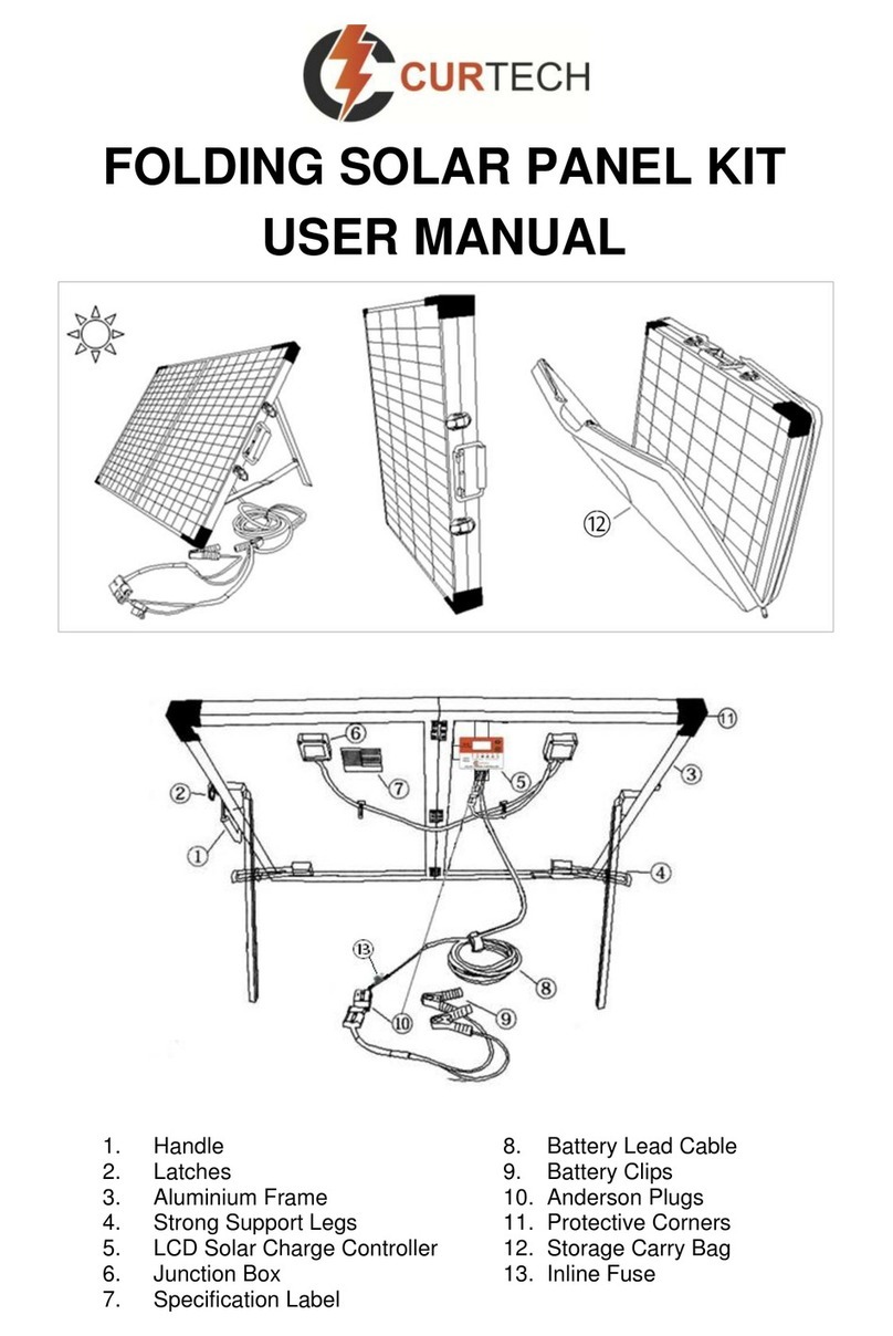
Curtech CT-K80 user manual
ring
ring 5F78E9 Setup guide

MSW
MSW S-POWER SYSTEM LIS 3000 PRO user manual
Owens Corning
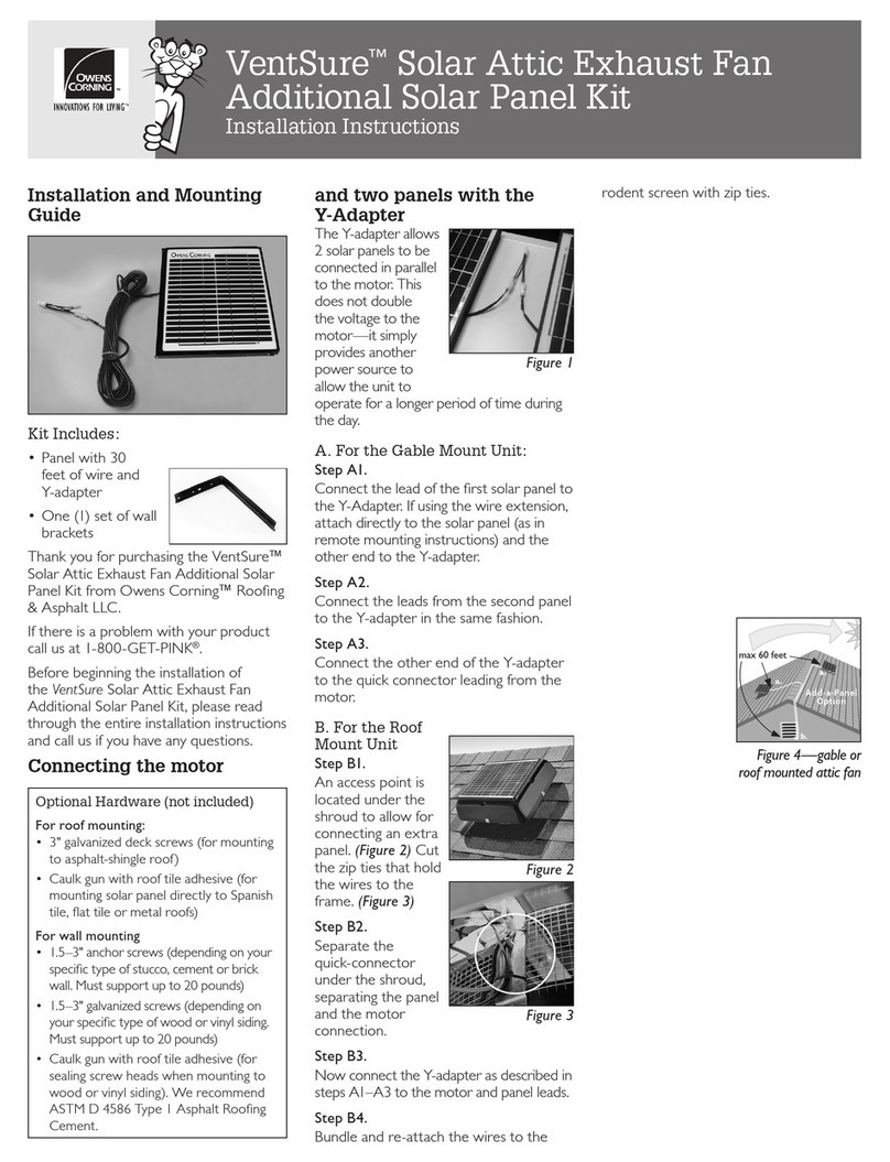
Owens Corning VentSure Solar Attic Exhaust Fan Additional Solar Panel... installation instructions

Champion Global Power Equipment
Champion Global Power Equipment 201246 Operator's manual

